
Virtual Work/Unit Load Method
The Virtual Work Method is based on the principle of energy conservation. It equates the virtual external work done by a unit force or moment to the virtual internal work done by internal stresses and deformations.
Strain Energy
When a force acts on an elastic body, it stores energy as strain energy. For a linear elastic material:
- When the force increases linearly from 0 to $P$:
$$ W = \frac{1}{2} P \Delta $$
- When the force is constant:
$$ W = P \Delta $$
Similarly, for moments causing rotation:
- Linearly increasing moment:
$$ W = \frac{1}{2} M \theta $$
- Constant moment: $$ W = M \theta $$
Principle of Virtual Work
More specifically: $$ (\text{real displacement}) \times (\text{virtual force}) = (\text{real internal displacement}) \times (\text{virtual internal force}) $$
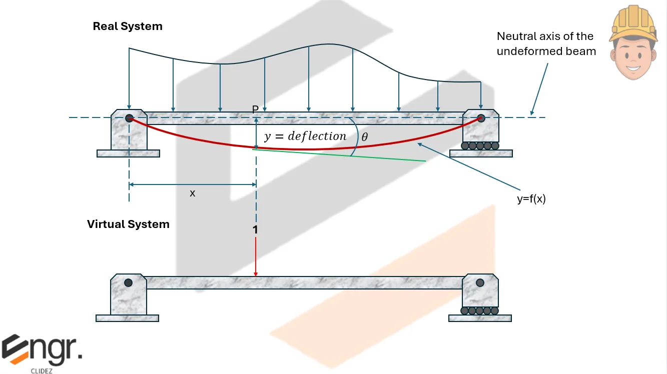
Virtual Work for Deflection and Rotation in Beams
To compute the deflection $\Delta$ at a point, apply a unit load at that point in the direction of the desired deflection. Then:
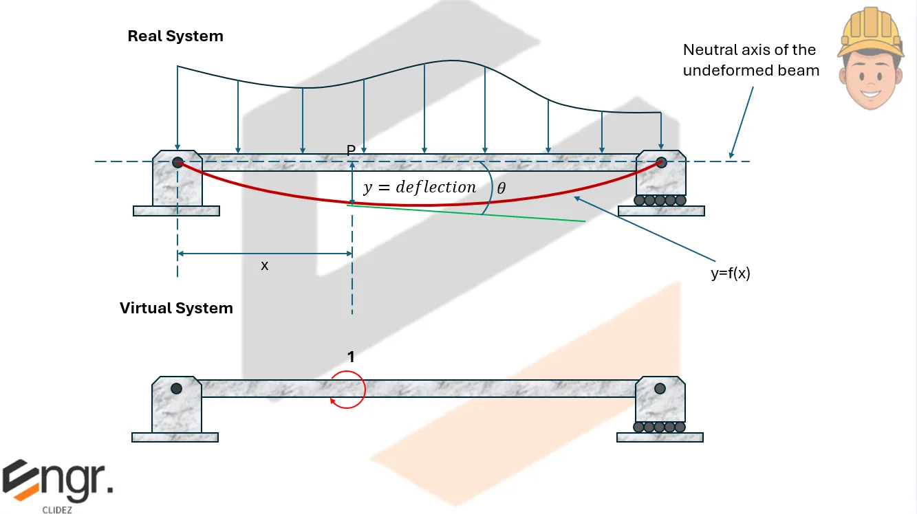
To compute the rotation $\theta$ at a point, apply a unit moment (couple) at that point in the direction of the desired rotation. Then:
Where:
- $M$ is the moment from the real loading
- $M_v$ is the moment from the virtual system unit load or moment
- $EI$ is the flexural rigidity of the beam
Summary of Procedure
- Identify the location and type of displacement or rotation to be found.
- Apply a unit load for deflection or unit moment for rotation at that location and direction.
- Find internal moment expressions $M$ and $M_v$ for both the real and virtual systems across each segment.
- Use the integral $$ \int_0^L \frac{M \cdot M_v}{EI} dx $$to find the desired deflection or rotation.


