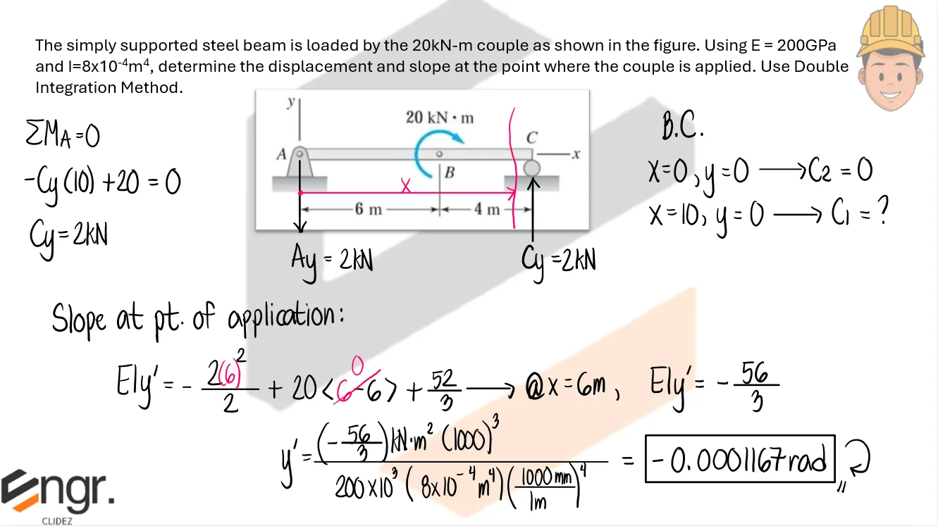
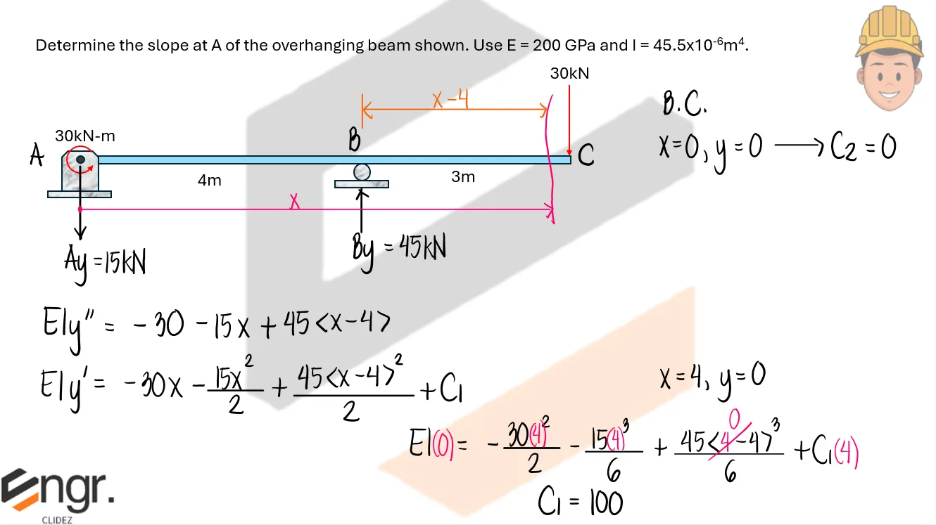
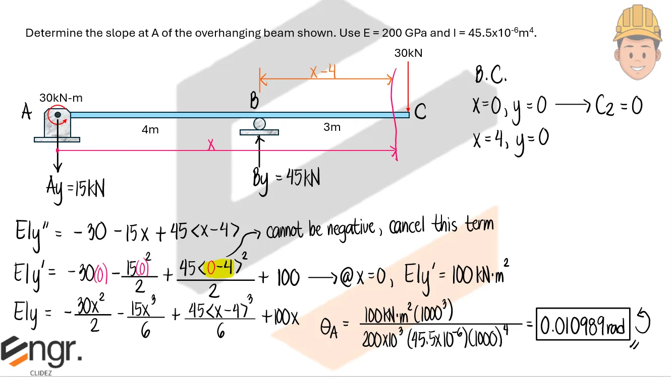
Double Integration Method
Beam deflection refers to the displacement of a structural element under load. Understanding how beams bend and deform is essential for ensuring structural safety and serviceability. In engineering, various methods are used to calculate beam deflections, each suited for specific types of loads, supports, and material behavior. One fundamental method is the Double Integration Method, which uses calculus and moment equations to determine the slope and deflection along the length of the beam.
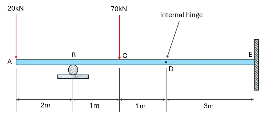
Setting the left end as the origin for the beam, at point \( P \), a distance \( x \) from the origin, the deflection is \( y \) and the slope of the elastic curve is \( \theta \).
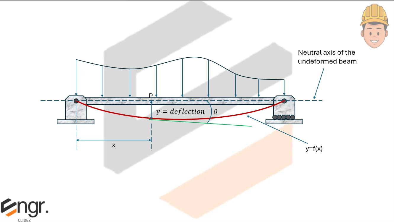
Let \( y = f(x) \) be the equation of the elastic curve. From calculus, the radius of curvature of a curve \( y = f(x) \) is given by the formula:
Deflection of beams is so small that the slope \( \dfrac{dy}{dx} \) is very small, and squaring it gives approximately zero. Hence, we have:
From Strength of Materials, the radius of curvature of the beam subjected to bending is:
Equating the two expressions for \( \rho \), we have:
or
Equation above is known as the differential equation of the elastic curve.
Where:
\( E \) = modulus of elasticity of the beam material
\( I \) = moment of inertia of the beam cross-section
\( EI \) = flexural rigidity (product of \( E \) and \( I \))
\( M \) = bending moment at the point \( P \)
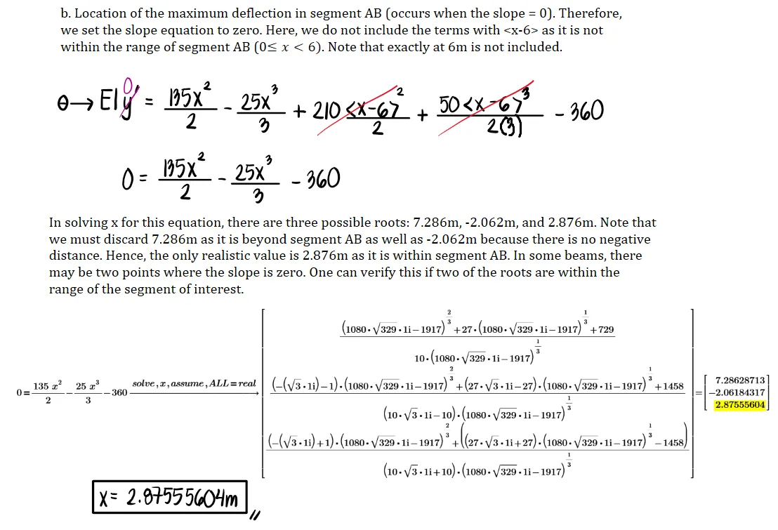
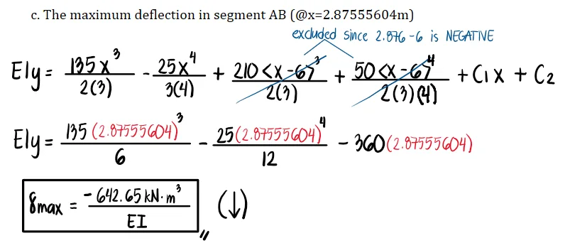
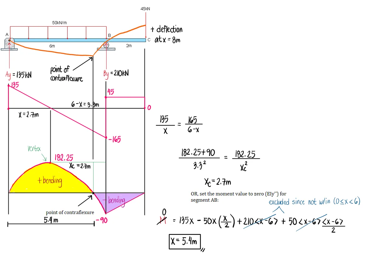
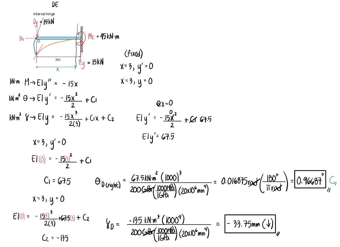
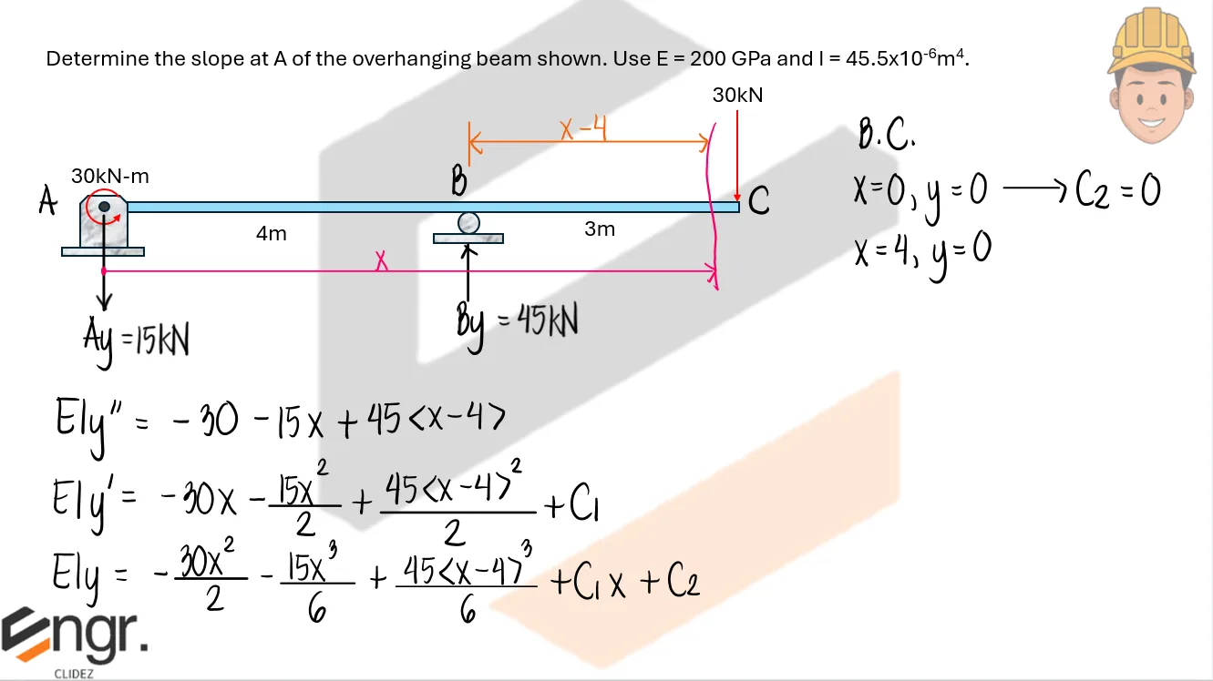
The first integration gives:
This is the slope equation. Note that \( \tan \theta = \dfrac{dy}{dx} \), but for small angles, \( \tan \theta \approx \theta \), thus:
Note that \( \theta \) is also the rotation of the beam at the given point.
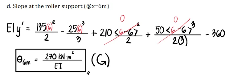
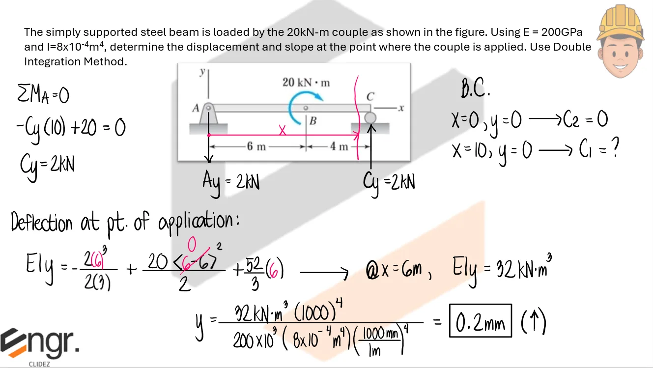
The second integration gives:
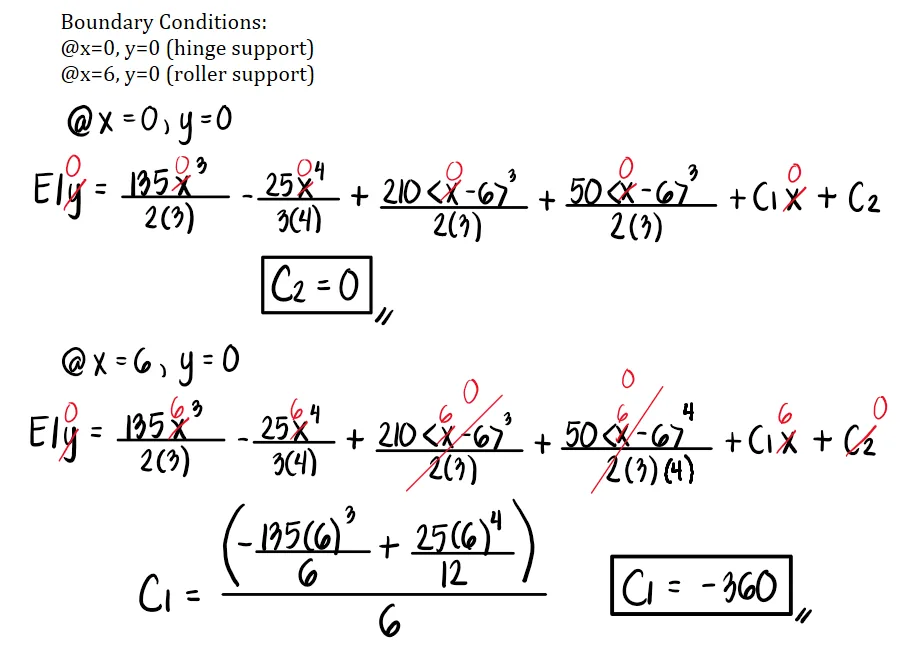
This is called the deflection equation, where \( C_1 \) and \( C_2 \) are constants of integration that can be solved using known boundary conditions.