
Castigliano's Second Theorem
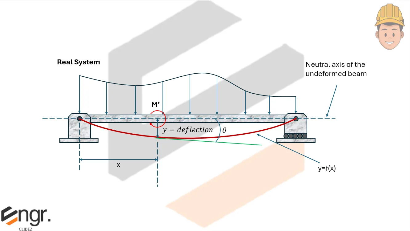
Castigliano's Theorem is a method used to calculate the deflection or slope at a specific point in a structure by applying a virtual load or moment. The theorem is applicable to linearly elastic systems.
The two main equations are:
How to Use the Theorem:
- To find deflection at a point, apply a virtual load $P$ at that point.
- To find slope at a point, apply a virtual moment $M'$ at that point.

Segment-by-Segment Consideration:
- You may integrate from left to right or right to left depending on your chosen origin.
- If integrating from the left, include all loads to the left of the section.
- If integrating from the right, include all loads to the right of the section.
Notes on Moment Expression:
- $M$ refers to the bending moment expression including the virtual load or moment $P$ or $M'$.
- Always verify your sign convention and assumption when setting up $M$:
- ⊕ Positive: correct assumption
- ⊖ Negative: wrong assumption
Understanding the Moment Expression in Castigliano's Theorem
In Castigliano's method, we work with the moment equation from the real beam, denoted as $M_R$. This excludes the virtual load $P$ or virtual moment $M'$, which are set to zero.
To compute deflection or slope, we use the following expressions:
- $\frac{\partial M}{\partial P}$ partial derivative of the moment $M$ with respect to virtual load $P$
- $\frac{\partial M}{\partial M'}$ partial derivative of $M$ with respect to virtual moment $M'$
Key Idea:
Differentiate the moment equation while treating everything else as a constant, except the term you're differentiating with respect to --> $P$ or $M'$.
Example 1: With respect to $P$
Given the moment equation:
Differentiate with respect to $P$:
Example 2: With respect to $M'$
Given the moment equation:
Differentiate with respect to $M'$:
This step-by-step differentiation allows us to substitute into Castigliano's Theorem integrals to compute either deflection $\delta$ or slope $\theta$ at the point of interest.


