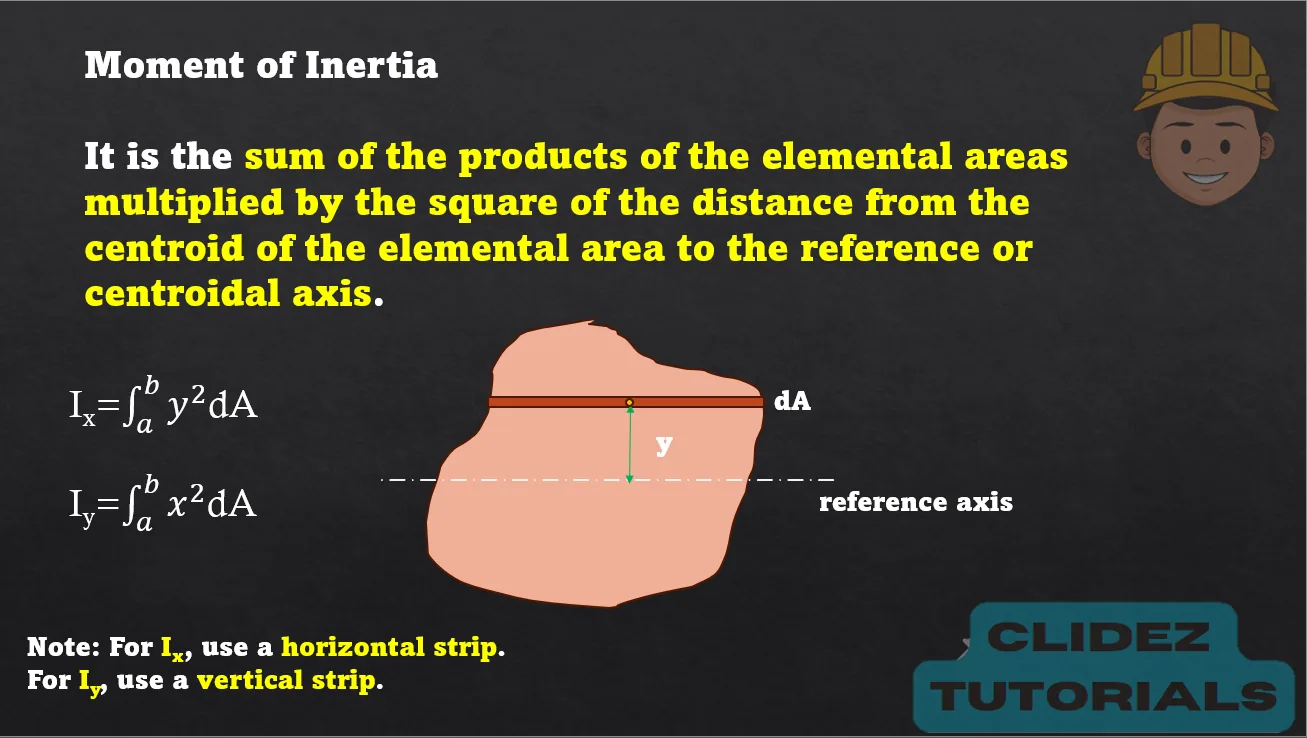
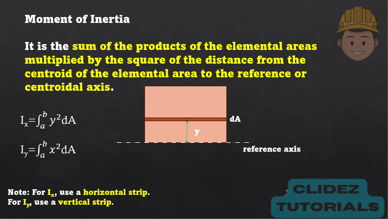
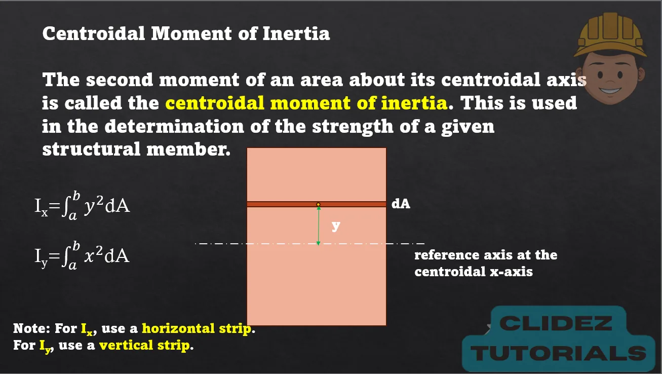
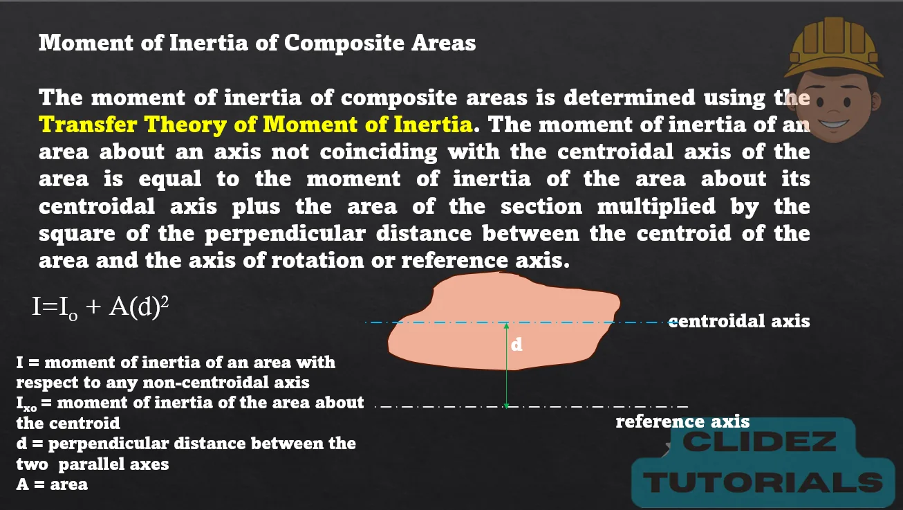
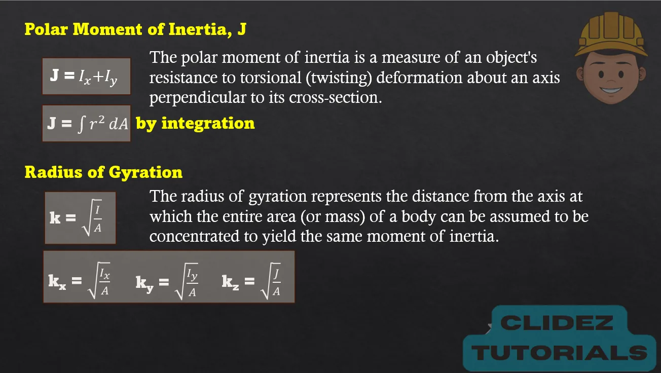
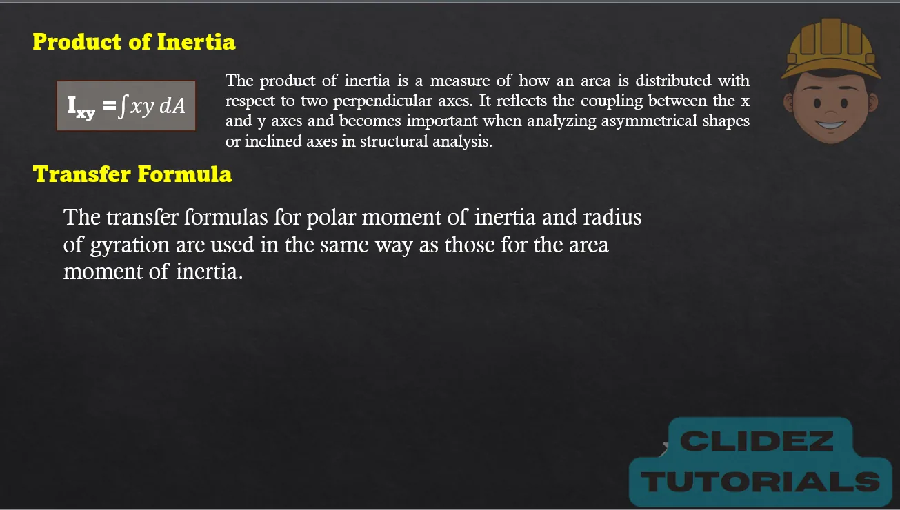
Moment of Inertia


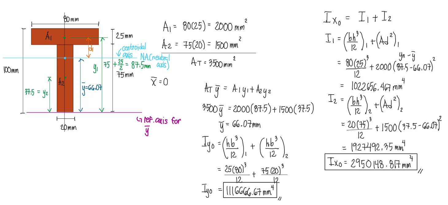
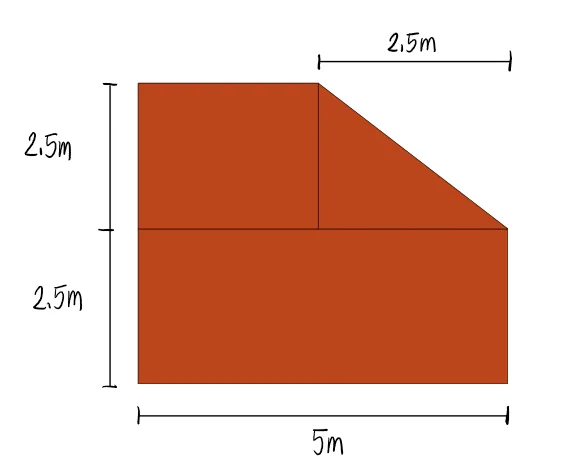
For the given figure, locate the centroid and solve the moment of inertia about the centroidal axes.
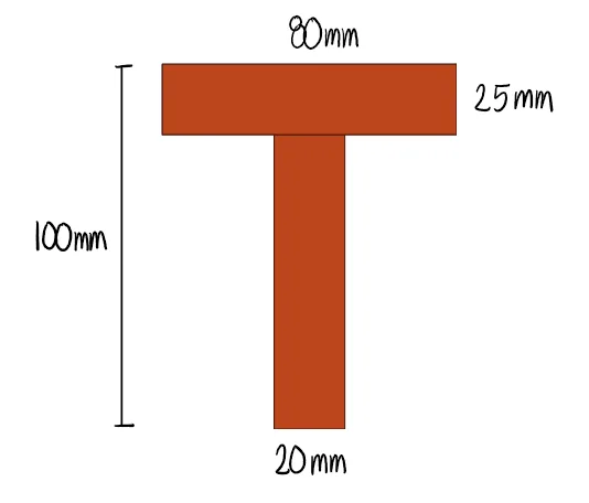


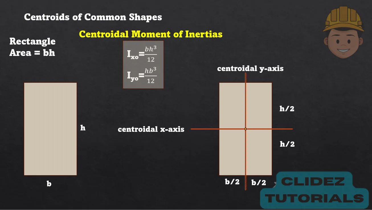
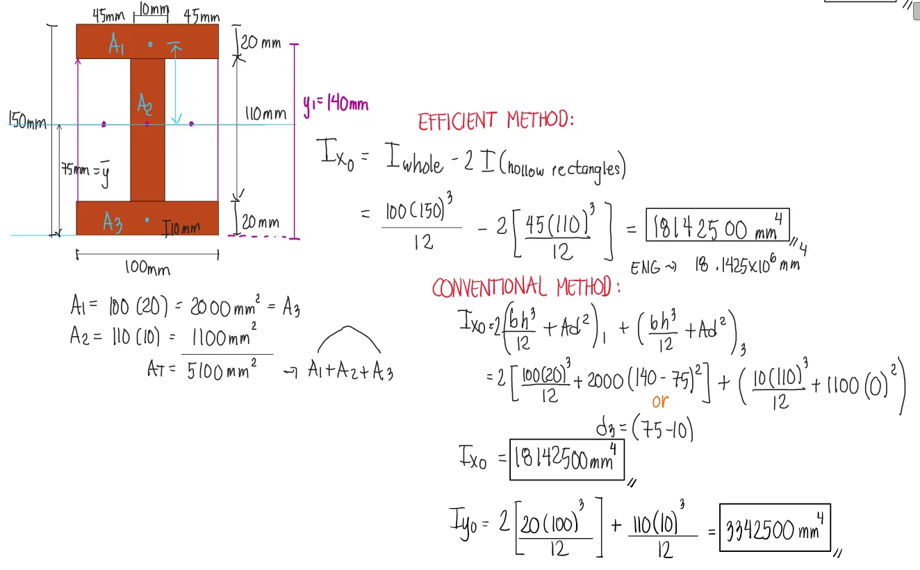
The figure below has a vertical axis of symmetry, meaning that the centroidal y-axis is located along this axis. Therefore, we don't have to apply the transfer formula for the moment of inertia about the y-axis and we simply add the individual Iyo of each shape. However, the centroidal x-axes of each shape does not coincide with the centroidal x-axis of the total shape. Thus, we need to apply the transfer formula, Ad2, to transfer the centroidal moment of inertia of each shape to the centroid of the total figure.


For the given figure, locate the centroid and solve the moment of inertia about the centroidal axes.


See images:
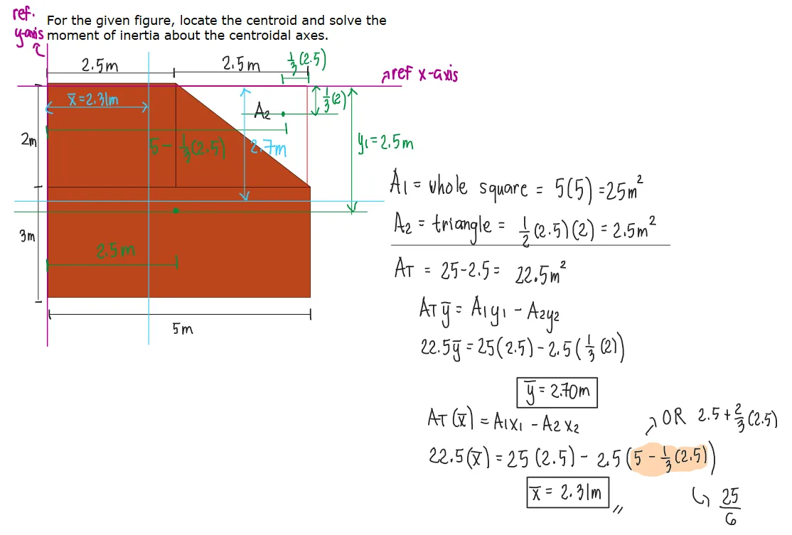
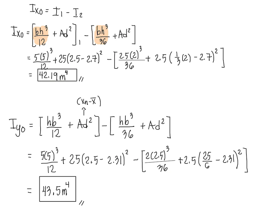
We applied the same method used in the previous chapter for finding centroids, where hollow sections are subtracted. Similarly, to determine the total centroidal moment of inertia, we must also use subtraction—specifically, by subtracting the transformed centroidal moment of inertia of the hollow section from that of the larger solid section.


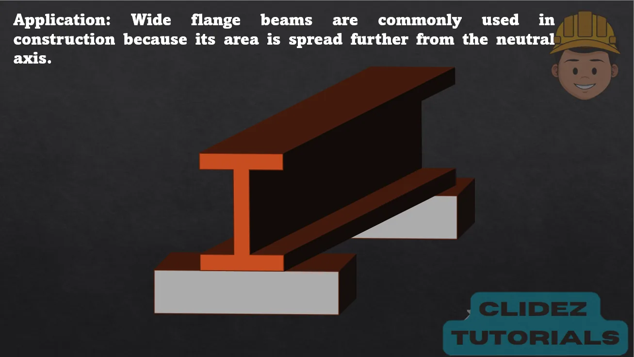
A wide flange section has the following dimensions: Flange thickness = 20mm
Flange width = 100mm
Total depth = 150mm
Web thickness = 10mm
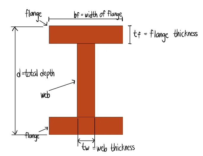


See images:


For the given figure, locate the centroid and solve the moment of inertia about the centroidal axes.
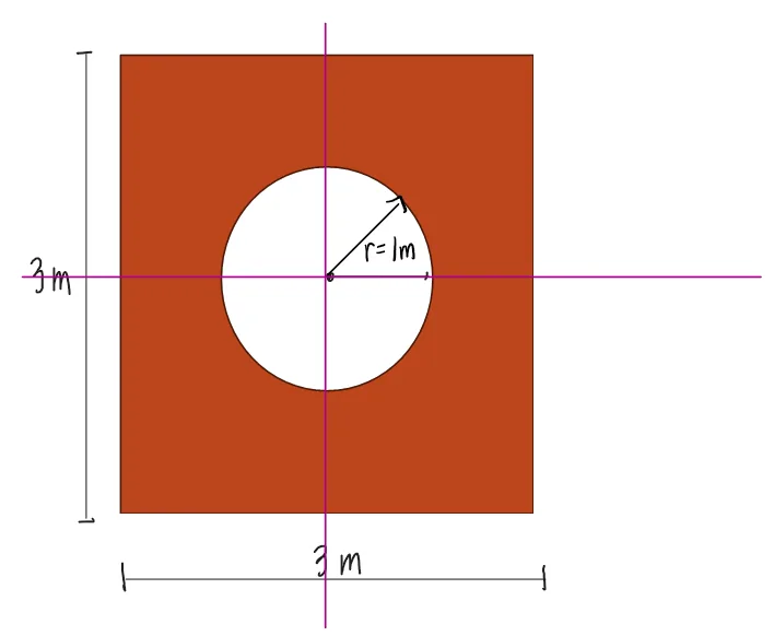


Since the figure has a vertical and horizontal axis of symmetry, the centroid is immediately located at the geometric center.
Then, by symmetry: Ixo=Iyo
Ixo = Iyo = Isquare - Icircle=$\frac{bh^3}{12} - \frac{\pi D^4}{64}$
$$
\frac{3\cdot3^3}{12} - \frac{\pi\cdot2^4}{64}=5.96m^4
$$


Compute the moment of inertia about the centroidal x-axis of the beam shown.


To solve this strategically, we consider this shape as a large rectangle minus a trapezoid. We can rotate the trapezoid by 90º and solve its Iy. Then, the solution becomes Iwhole rectangle minus twice of Iy of the rotated trapezoid.
However, in this solution, we will retain the original figure and just multiply the moment of inertias of four hollow triangles with their transfer formulas by four, then the hollow rectangles will be multiplied by two (no need for transfer formula since the centroids of the hollow rectangles coincide with the figure's neutral axis).


Refer to the image shown:


See images:


Refer to the image shown:


See images:


Refer to the image shown:


See images:


