Rotational Equilibrium: The sum of all moments about any point must also be zero
$$\sum M = 0$$
In engineering mechanics, a non-concurrent force system refers to a group of forces whose lines of action do not intersect at a single point. These forces may act on different parts of a rigid body and can include forces and moments (torques). To achieve equilibrium in such systems, a body must satisfy both conditions above.
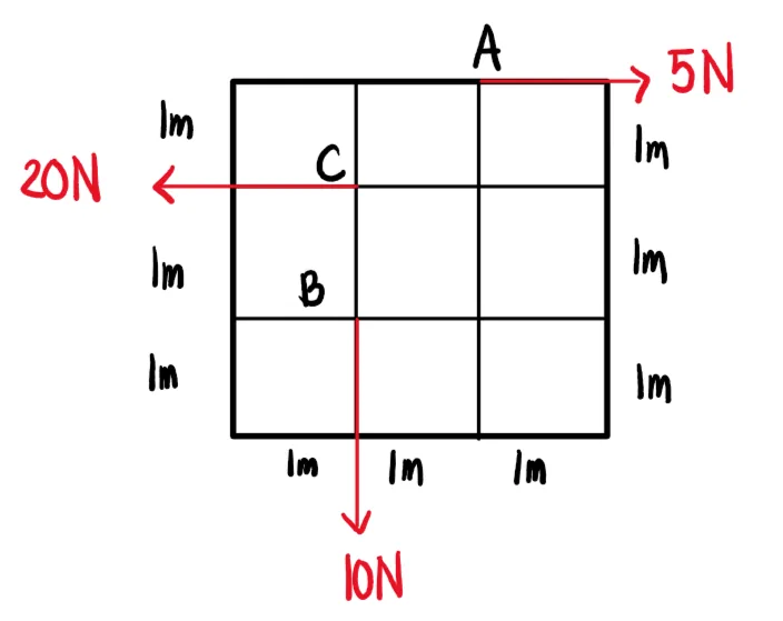
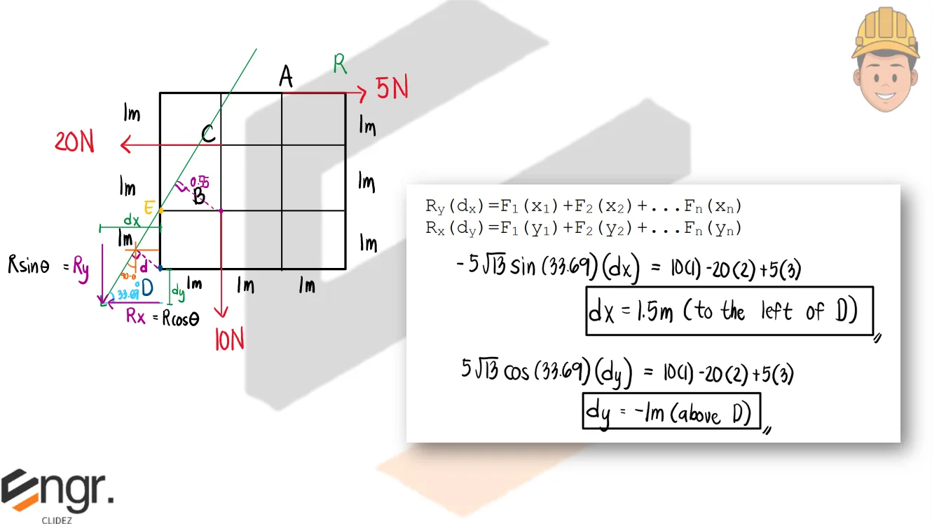
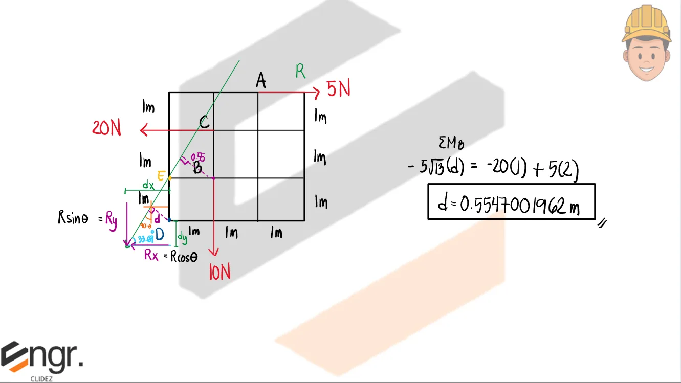
General Resultant of Non-concurrent Force Systems:
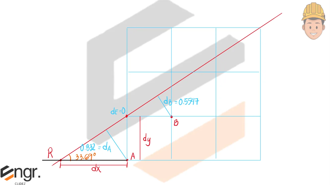
a. Calculate the location of the resultant from point D. b. Prove that the resultant force intersects point E (as indicated below) c. Determine the distance dx and dy from point D to the resultant force and indicate the location relative to D. d. Determine the distance from point B to the resultant force. e. Resolve the system into a resultant-couple system.
See images:
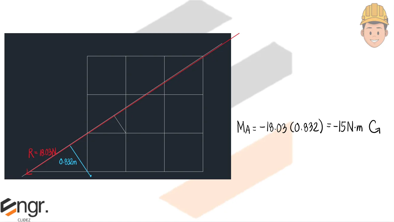
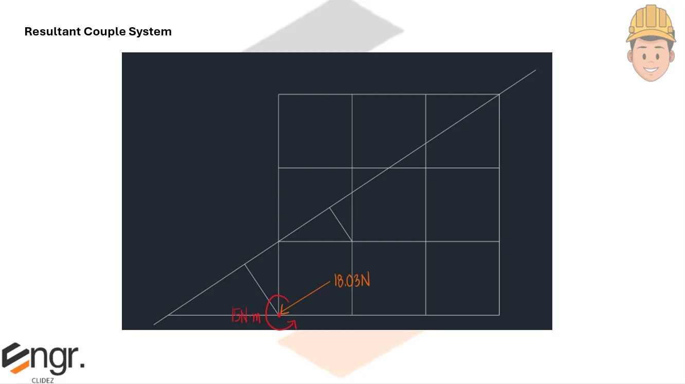
Below is a scaled drawing of the figure (modeled using AutoCad).We can obtain the moment caused by the resultant force about point D so that we can transfer the resultant so that it intersects point D. The moment (couple) will be applied at point D for clarity. Finally, we have this resultant-couple system that replaces the system above.
Problem 2:
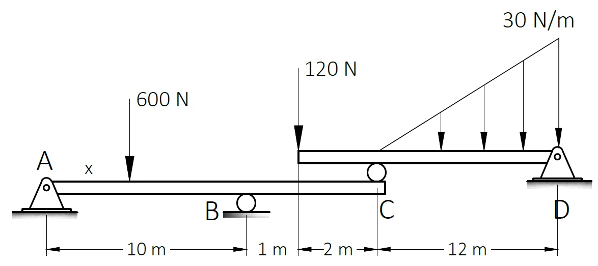
For the beam shown, beam ABC is supporting beam CD.
Which of the following most nearly gives the reaction at C in kN.
A. 250
B. 150
C. 100
D. 200
Which of the following most nearly gives the reaction at D in kN.
A. 250
B. 150
C. 100
D. 200
Which of the following most nearly gives the value of "x" if the reaction at B is 380 N.
A. 1
B. 1.5
C. 2
D. 3
See images:
Problem 3:
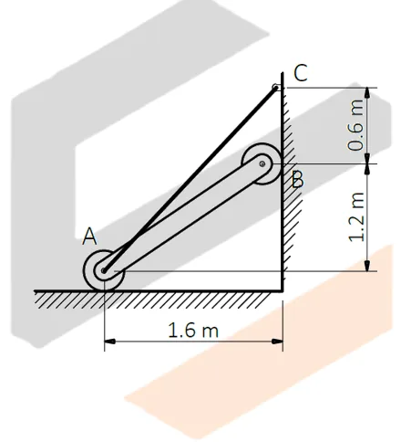
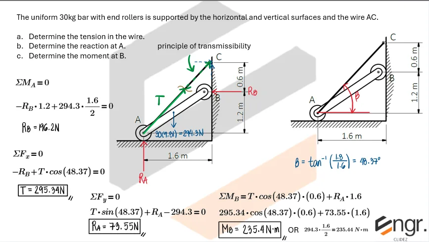
The uniform 30kg bar with end rollers is supported by the horizontal and vertical surfaces and the wire AC.
a. Determine the tension in the wire.
b. Determine the reaction at A.
c. Determine the moment at B.
See images:
Problem 4:
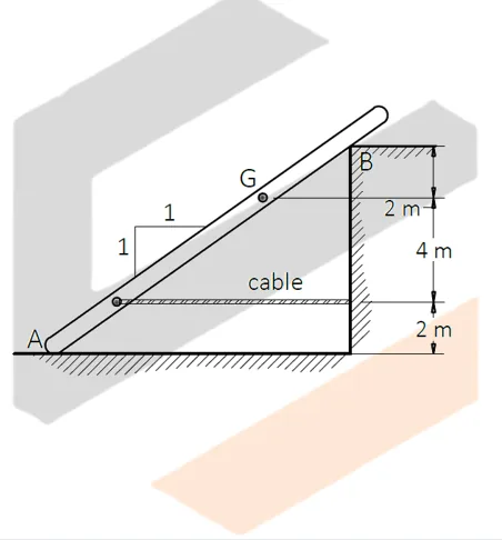
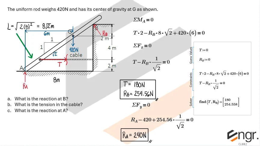
The uniform rod weighs 420N and has its center of gravity at G as shown.
a. What is the reaction at B?
b. What is the tension in the cable?
c. What is the reaction at A?
See images:
Problem 5:
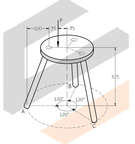
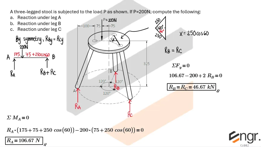
A three-legged stool is subjected to the load P as shown. If P=200N, compute the following:
a. Reaction under leg A
b. Reaction under leg B
c. Reaction under leg C
See images:
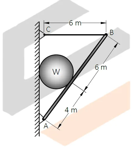
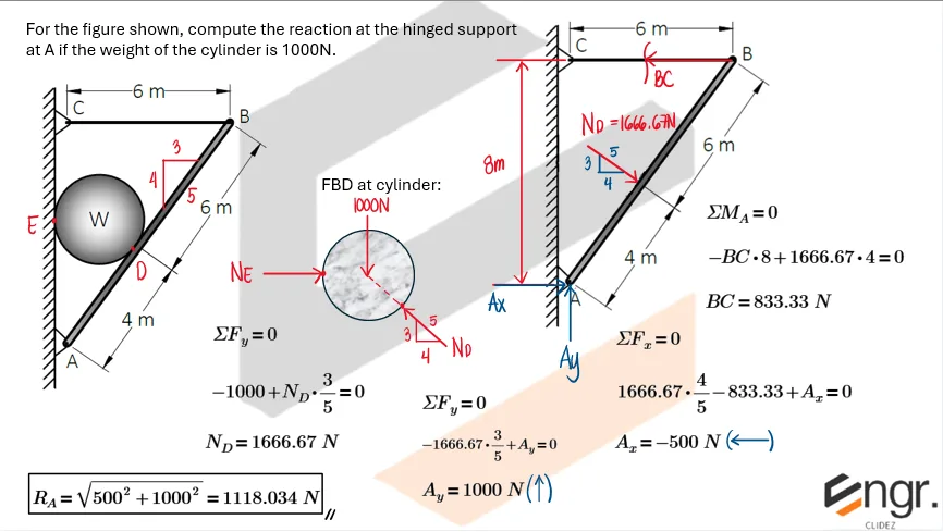
Problem 6:
For the figure shown, compute the reaction at the hinged support at A if the weight of the cylinder is 1000N.
See images:
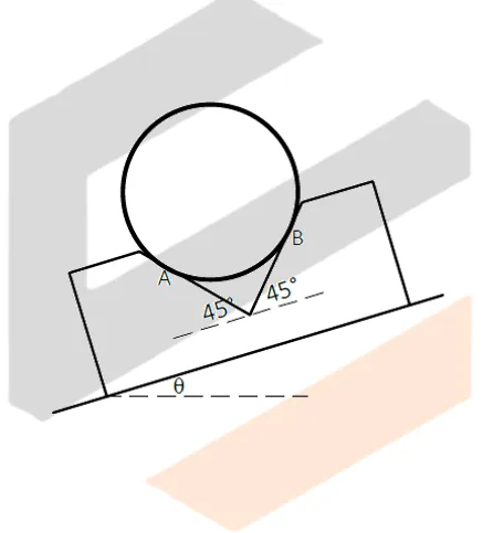
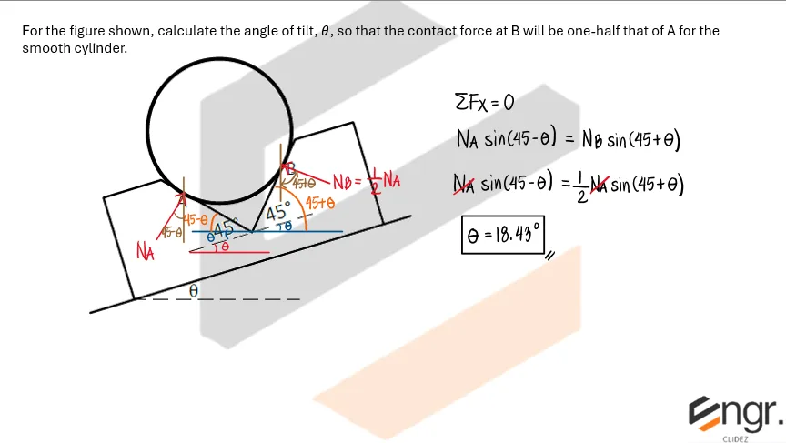
Problem 7:
For the figure shown, calculate the angle of tilt, θ, so that the contact force at B will be one-half that of A for the smooth cylinder.
See images:
Problem: Walkway from a Pier to a Float
To accomodate the rise and fall of tide, a walkway from a pier to a float is supported by two rollers as shown. The center of mass of the 300-kg walkway is at G.
a. Calculate the force under the roller at A in Newtons.
b. Calculate the tension T in the horizontal cable which is attached to the cleat in Newtons.
c. Calculate the force in the roller at B in Newtons.