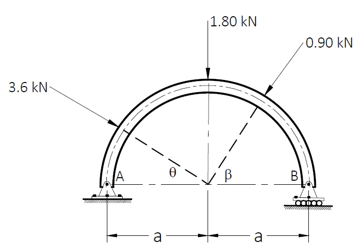
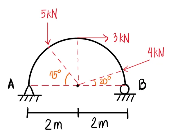
CE Board Exam Randomizer

β¬… Back to Subject Topics

Arches

Arches are used in construction to efficiently transfer loads to supports while allowing open spaces beneath. In this lecture, we focus on two common types: parabolic and circular arches. Parabolic arches are ideal for uniformly distributed loads, as their shape closely matches the natural thrust line, minimizing bending moments. They’re commonly used in bridges and long-span roofs where load uniformity is expected. Circular arches, on the other hand, are easier to construct and are often used in shorter spans or when aesthetics and tradition are prioritized, like in masonry arches or historical structures. However, they tend to generate higher bending moments under non-uniform loading. Understanding their structural behavior helps engineers choose the most efficient arch type based on span, load condition, material, and construction practicality.

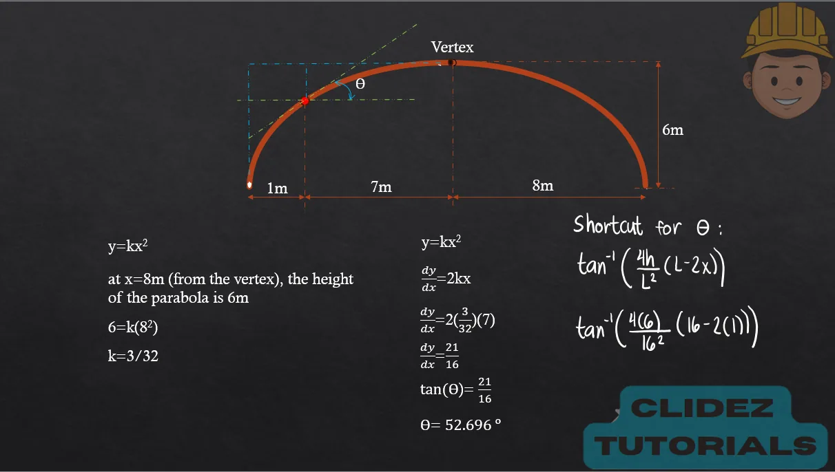
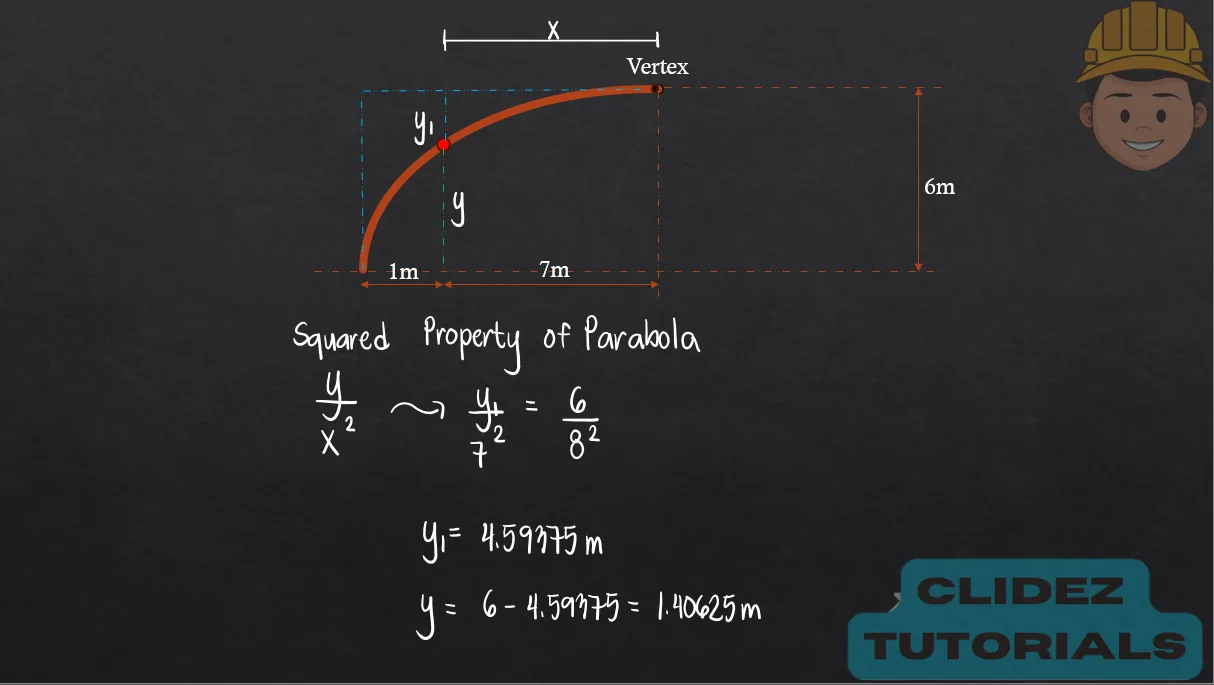
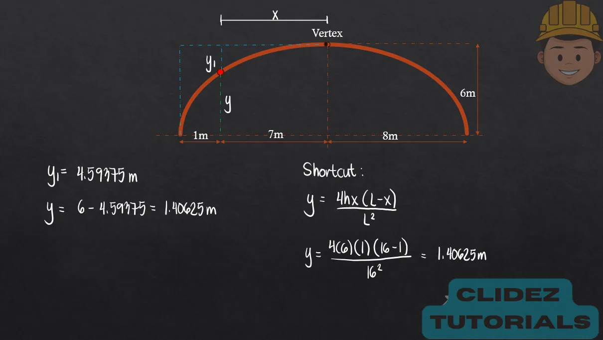
    Equation for Arch Profile (Parabolic Arch):
$$ y = \frac{4hx(L - x)}{L^2} $$
    Shortcut Formula for Arch Slope:
$$ \theta = \tan^{-1} \left( \frac{4h}{L^2}(L - 2x) \right) $$
Concept Concept Concept Concept Concept Concept Concept Concept Concept Concept

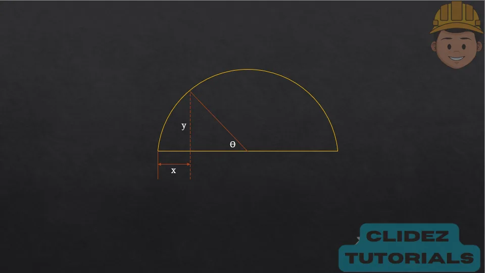
In the case of a circular arch, especially a semicircular arch, the method of analysis still follows the principles of static equilibrium. However, the geometry is based on circular coordinates. Referring to the diagram, if the radius of the arch is 𝑅 R and the angle πœƒ ΞΈ is measured from the vertical, the coordinates of a point on the arch are:

$$ x = R - R \cos \theta $$
$$ y = R \sin \theta $$
These equations locate points along the top half of a vertical circle, starting from the crown (πœƒ=0ΒΊ) down to the springing points (πœƒ=90ΒΊ ). While the analysis steps for internal forces are similar to those of parabolic arches, the curvature causes non-zero bending moments even under uniform loading, since the circular shape doesn’t naturally follow the thrust line.

Concept

Problem 1:

Refer to the image shown:

Diagram Diagram Diagram

See images:

Solution Solution Solution Solution

Problem 2:

Refer to the image shown:

Diagram Diagram Diagram

See images:

Solution Solution Solution Solution

Problem 3:

Refer to the image shown:

Diagram Diagram Diagram

See images:

Solution Solution Solution Solution

Problem 4:

Refer to the image shown:

Diagram Diagram Diagram

See images:

Solution Solution Solution Solution

Problem 5:

Refer to the image shown:

Diagram Diagram Diagram

See images:

Solution Solution Solution Solution

Problem 6:

Refer to the image shown:

Diagram Diagram Diagram

See images:

Solution Solution Solution Solution

Problem 7:

Refer to the image shown:

Diagram Diagram Diagram

See images:

Solution Solution Solution Solution

Problem 8:

Refer to the image shown:

Diagram Diagram Diagram

See images:

Solution Solution Solution Solution