
Welded Connections
Welded connections are widely used in steel structures to transfer loads between members. They provide rigidity, continuity, and strength by joining structural components through welds. The strength of a welded connection depends on the electrode type, the configuration of the welds, and the stresses produced by direct loads and moments. The polar moment of inertia of the weld group is an important parameter in determining the distribution of stresses within the welds.
Electrode used:
- E60xx : $F_u = 415 \; \text{MPa}$
- E70xx : $F_u = 485 \; \text{MPa}$
- E80xx : $F_u = 550 \; \text{MPa}$
Polar Moment of Inertia
Simplified Form:
Where:
- $L$ = length of the weld
- $\bar{x}$ = horizontal distance between the point of consideration and the weld center
- $\bar{y}$ = vertical distance between the point of consideration and the weld center
Load Effects on Welds
Due to direct load:
Due to moment/torsion:
Minimum Size of Fillet Welds
| Material Thickness of Thicker Part Joined (mm) | Minimum Size of Fillet Weld (mm) |
|---|---|
| To 6 mm | 3 mm |
| Over 6 to 12 mm | 5 mm |
| Over 12 to 20 mm | 6 mm |
| Over 20 mm | 8 mm |
Maximum Size of Fillet Welds
| Material Thickness | Maximum Size of Fillet Weld |
|---|---|
| < 6 mm | Not greater than thickness of material |
| > 6 mm | Not greater than thickness of material minus 1.6 mm |
Welded Connections (Axially Loaded)
I. Longitudinal Fillet Welds Only
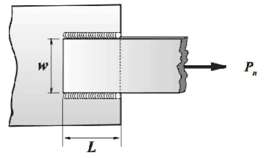
A. Tensile Capacity of Base Metal Connection
1) Tension Yielding on Gross Area
Pa = 0.60 Pn (For ASD)
Pu = 0.90 Pn (For LRFD)
2) Tension Rupture on Net Section of the Base Metal
Ae = UAn, An = Ag (since there are no bolt holes for welds)
Pa = 0.50 Pn (For ASD)
Pu = 0.75 Pn (For LRFD)
Where:
Fy = yield stress of the base metal
Fu = specified ultimate stress of the base metal
t = thickness of the base metal
U = shear lag factor
Note: Use the smaller value of Pn for tensile capacity of the base metal.
Shear Strength of the Base Metal
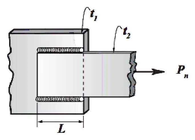
1) Based on Gross Area of Shear Surface
Ag = t(Lt)
t = smaller thickness of t1 and t2
Lt = total length of the weld
2) Based on Shear Rupture Strength
Anv = t(Lt)
t = smaller thickness of t1 and t2
Lt = total length of the weld
Pa = 0.50 Pn (For ASD)
Pu = 0.75 Pn (For LRFD)
3) Weld Shear Strength
Where:
Awe = 0.707 (t)(Lt)
t = thickness of the weld in mm
Fnw = 0.60 Fu (tension strength of the weld)
Lt = total length of the longitudinal welds
Load Resistance Factored Design (LRFD)
Where: Φ Pn = design shear strength of weld, Φ=0.75
Allowable Stress Design (ASD)
Where: Pa = design shear strength of weld, Ω = 2
II. Longitudinal & Transverse Fillet Welds
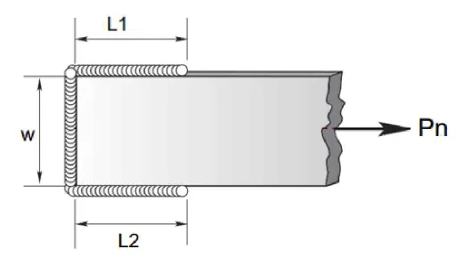
$$P_{n2} = 0.85 Pn_{wl} + 1.5 Pn_{wt}$$
Where:
Pnwl = total nominal strength of the longitudinal fillet welds
Pnwt = total nominal strength of the transversely loaded fillet welds
Pnwl = Fnw (Awe)
Note: Use the larger value between Pn1 and Pn2 as the design Pn.


