
Shear Stress and Deflection
Shearing Stress Distribution for a W-shape
The shear stress at a level in the section is given by (recall from Mechanics of Deformable Bodies):
For a W-shape, the distribution is shown in the figure below. Superimposed on the actual curve is the
average web shear stress:
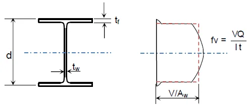
Because this average value is close to the maximum stress in the web, the web carries most of the shear and will reach yield before the flanges. Therefore, yielding of the web constitutes one of the shear limit states.
SECTION 507 — DESIGN OF MEMBERS FOR SHEAR
(tension-field action not included)507.1 General Provisions
The design shear strength and allowable shear strength are:
For all provisions in this section except Section 507.2.1(1):
507.2 Members with Unstiffened or Stiffened Webs
507.2.1 Nominal Shear Strength
This applies to the webs of singly or doubly symmetric members and channels subjected to shear in the plane of the web. The nominal shear strength considering shear yielding and shear buckling is:
Shear Provisions — Web Coefficients
1) Rolled I-shapes (webs)
When
use
2) All other doubly symmetric shapes, singly symmetric shapes, and channels (round HSS excluded)
The web shear coefficient Cv is determined from:
-
For
$$ \frac{h}{t_w} \le 1.10\sqrt{\frac{k_v E}{F_y}} $$$$ C_v = 1.0 $$ -
For
$$ 1.10\sqrt{\frac{k_v E}{F_y}} < \frac{h}{t_w} \le 1.37\sqrt{\frac{k_v E}{F_y}} $$$$ C_v = \frac{1.10\sqrt{\frac{k_v E}{F_y}}}{\frac{h}{t_w}} $$ -
For
$$ \frac{h}{t_w} > 1.37\sqrt{\frac{k_v E}{F_y}} $$$$ C_v = \frac{1.51\,k_v\,E/F_y}{\left(\frac{h}{t_w}\right)^2} $$
Web plate buckling coefficient, kv
-
Unstiffened webs: if
$$ \frac{h}{t_w} < 260 $$$$ k_v = 5 \qquad \text{(use } k_v = 1.2 \text{ for the stem of tee sections)} $$ -
Stiffened webs:
$$ k_v = 5 + \frac{5}{\left(\frac{a}{h}\right)^2} $$However, take
$$ k_v = 5 \quad \text{when } \frac{a}{h} > 3.0 \; \text{or} \; \frac{a}{h} > \left[\frac{260}{\frac{h}{t_w}}\right]^2 $$
Symbols
Aw = web area, $A_w = d\,t_w$ (mm2)
a = clear spacing between transverse stiffeners (mm)
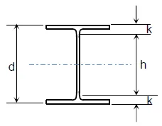
h = for rolled shapes, clear distance between flanges (minus fillet/corner radii);
for built-up welded shapes, clear distance between flanges;
for built-up bolted shapes, distance between fastener lines;
for tees, the overall depth (mm)
509.3.1.1 Effective Width
The effective width of a concrete slab is defined as the sum of the effective widths on each side of the beam centerline. Each portion must not exceed:
- One-eighth of the beam span (center-to-center of supports);
- One-half of the distance to the centerline of the adjacent beam; or
- The distance to the slab edge.
509.3.2 Strength of Composite Beams with Shear Connectors
509.3.2.1 Positive Flexural Strength
The design positive flexural strength, φbMn, and the allowable positive flexural strength, Mn/Ωb, are determined for the limit state of yielding as follows:
-
For
$$ \frac{h}{t_w} \le 3.76 \sqrt{\frac{E}{F_y}} $$Mn is based on the plastic stress distribution for the composite section (plastic moment).
-
For
$$ \frac{h}{t_w} > 3.76 \sqrt{\frac{E}{F_y}} $$Mn is based on the elastic stress distribution, considering shoring effects (yield moment).
509.3.2.4 Shear Connectors
Load Transfer for Positive Moment
The total horizontal shear at the steel→concrete interface is assumed to be fully transferred by shear connectors (except in concrete-encased beams covered under Section 509.3). For composite action with concrete under flexural compression, the total horizontal shear force, V′, shall be taken as the smallest of the following:
-
Concrete crushing:
$$ V' = 0.85\, f'_c A_c $$ -
Tensile yielding of the steel section:
$$ V' = F_y A_s $$ -
Strength of shear connectors:
$$ V' = \Sigma Q_n $$
Where:
Ac = concrete slab area within effective width (mm2)
As = area of steel cross-section (mm2)
ΣQn = sum of nominal strengths of shear connectors between maximum positive moment and point of zero moment (N)


