Flexure Members
NSCP 2010 / 2015 (Load and Resistance Factor Design - LRFD)
Critical Buckling Stress, Fcr
For a doubly symmetric I-shape: c = 1
The limiting lengths Lp and Lr are determined as follows:
NOTE: rts may be approximated accurately and conservatively as the radius of gyration of the compression flanges plus one-sixth of the web:
NOTE: The square-root term in the equation for Fcr may be conservatively taken as 1.0. The equation for Lr becomes:
506.2 Doubly Symmetric Compact I-Shaped Members and Channels Bent about their Major Axis. (Compact Flanges and Webs)
506.2.1 Yielding
506.2.2 Lateral Torsional Buckling
- When Lb $\le$ Lp, the limit state of lateral-torsional buckling does not apply.
-
When Lp < Lb $\le$ Lr,
$$ M_n = C_b \left[\, M_p - \left(M_p - 0.7\,F_y S_x\right) \left(\frac{L_b - L_p}{L_r - L_p}\right) \right] \le M_p $$
-
When Lb > Lr,
$$ M_n = F_{cr}\,S_x \le M_p $$
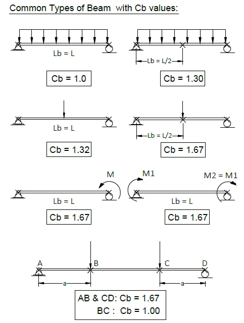
Moment Gradient Multiplier / LTB Modification Factor
This factor is used to account for the variation of moment diagrams when both ends of the unbraced length are supported. The expression for Cb is:
Where:
RM = cross-section monosymmetry parameter
= 1.0 for doubly symmetric members
= 1.0 for singly symmetric members under single curvature bending
506.3 Doubly Symmetric I-Shaped Members with Compact Webs and Noncompact or Slender Flanges Bent about their Major Axis
The nominal flexural strength, Mn, is determined as the smaller value governed by lateral-torsional buckling or compression flange local buckling.
506.3.1 Lateral-Torsional Buckling
For lateral-torsional buckling, the requirements of Section 506.2.2 apply.
506.3.2 Compression Flange Local Buckling
For sections with noncompact flanges:
For sections with slender flanges:
Where:
For calculation purposes, kc must not be taken less than 0.35 nor greater than 0.76.
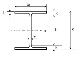
AISC Specification for Flexural Strength of Beams (Width-Thickness Parameters)
| Element | $$\lambda$$ | $$\lambda_p$$ | $$\lambda_r$$ |
|---|---|---|---|
| Flange | $$\frac{b_f}{2t_f}$$ | $$0.38 \sqrt{\frac{E}{F_y}}$$ | $$1.0 \sqrt{\frac{E}{F_y}}$$ |
| Web | $$\frac{h}{t_w}$$ | $$3.76 \sqrt{\frac{E}{F_y}}$$ | $$5.70 \sqrt{\frac{E}{F_y}}$$ |
Where:
λ = width→thickness ratio of the member
λp = upper limit for compact category
λr = upper limit for non-compact category
Then:
- When λ ≤ λp (and the flange is continuously connected to the web), the shape is compact.
- When λp < λ ≤ λr, the shape is non-compact.
- When λ > λr, the shape is slender.
NOTE: If the web is compact but the flange is non-compact, the section is classified as non-compact.
a) Compact Section:
Note: The web is compact for all hot-rolled shapes with Fy ≤ 65 ksi. No web check is required.
1. When the beam is laterally supported throughout its length (Lb ≤ Lp):
Where:
Lb = unbraced length
LRFD:
ASD:
2. When Lb > Lp and Lb < Lr (beam is laterally unsupported, inelastic lateral torsional buckling):
Where:
Mmax = maximum moment within the unbraced length (including end points)
MA, MB, MC = moments at quarter, mid, and three-quarter points
Rm = 1.0 for doubly symmetric and singly symmetric I-shapes
3. When Lb > Lp and Lb > Lr (beam is laterally unsupported, elastic lateral torsional buckling):
Where:
Additional Definitions:
$C_w$ = warping constant
$r_{ts}$ = effective radius of gyration
$h_o$ = distance between centroid of flanges
$0.70F_yS_x$ = moment adjustment for residual stress in flexural strength analysis
b) Non-Compact Sections
A. Based on Flange Local Buckling (FLB)
When $\lambda < \lambda_p$ — there is no FLB
When $\lambda_p < \lambda < \lambda_r$ — the flange is non-compact
B. Based on Lateral Torsional Buckling (LTB)
When $L_b < L_p$ — there is no LTB
When $L_p < L_b < L_r$ — there is inelastic LTB
When $L_b > L_r$ — there is elastic LTB
NOTE: Use $M_n$ which is the smaller value of the two criteria (A or B1) or (A or B2).
Types of Moment
Plastic moment about the major principal axis (x-axis):
Plastic moment about the minor principal axis (y-axis):
Yield moment that brings the beam to the point of yielding (subscript y means yield, not y-axis):
Yield moment about the y-axis:
Bending Stress and Plastic Moment
For linear elastic material with small deformations, the distribution of bending stress will be uniform across the width of the beam.
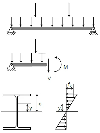
From the bending stress formula,
with a maximum stress at the farthest distance, c, from the x-axis,
where Sx is called the elastic section modulus.
As long as the applied loads remain within the material's linear elastic range, the maximum stress fmax must not exceed Fy, and the moment must not exceed:
where My is the bending moment that causes the beam to yield.
The figure below illustrates a simply supported beam with a concentrated load at midspan, shown at successive stages of loading.
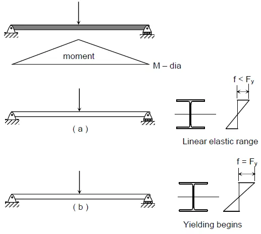
Once yielding begins, the stress distribution across the section becomes nonlinear, with yielding progressing inward from the outermost fiber toward the neutral axis. At the same time, the yield zone spreads along the length of the beam, beginning at midspan, as the bending moment reaches My. This is shown by the shaded regions in (c) and (d).
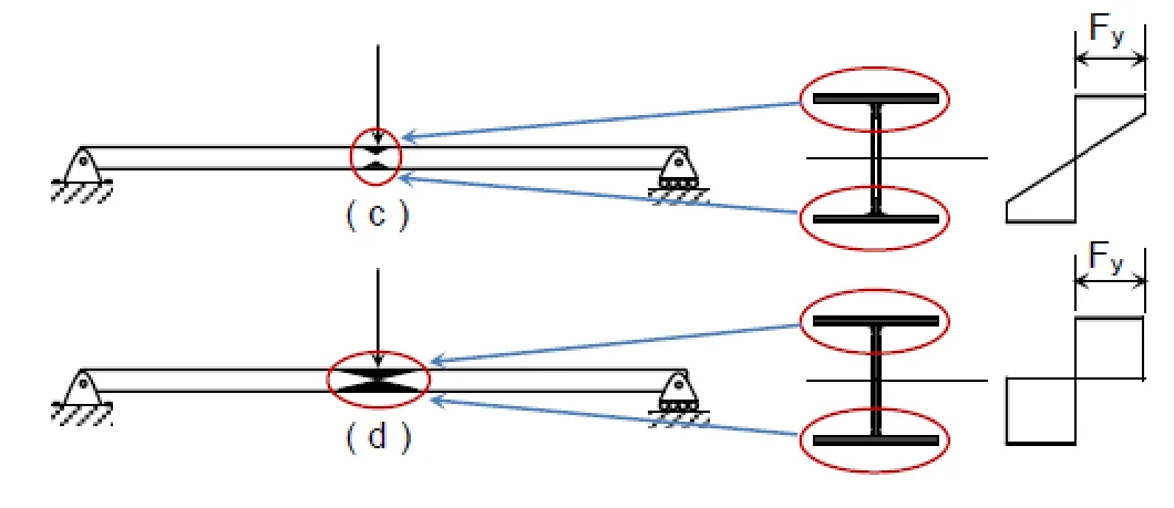
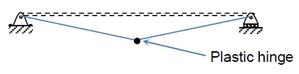
When stage (d) is reached, any additional load will lead to collapse, as the entire cross-section has entered the yield plateau of the stress→strain curve, allowing unrestricted plastic flow. At this point, a plastic hinge forms at the beam's midspan, as illustrated below. Together with the supports at the beam ends, this hinge creates an unstable mechanism.
Plastic Analysis and Plastic Moment
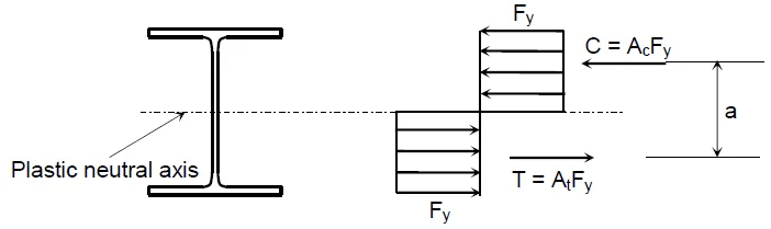
In plastic analysis, collapse is assessed by forming a plastic hinge. The moment required to form this hinge is the plastic moment, Mp. At the plastic neutral axis (PNA), the compressive and tensile resultants are equal:
The PNA splits the cross-section into two equal areas. For shapes symmetric about the bending axis, the elastic neutral axis and the plastic neutral axis coincide. The resisting couple from the two equal and opposite forces gives:
Here, Z is the plastic section modulus. For a section divided into two equal areas by the PNA, with a = distance between the centroids of the two half-areas and A = total area,
Definitions
A = total cross-sectional area
a = distance between centroids of the two half areas
Z = plastic section modulus
Shape Factor
The ratio of plastic moment to yield (elastic) moment is the shape factor:
where My = Fy S is the yield moment and S is the elastic section modulus. A “load factor” may be expressed as the (factor of safety) multiplied by the shape factor, depending on the design context.