
Beam Bearing Plate and Column Base Plate
Plates distribute concentrated loads to the supporting material. A beam transfers its reaction to a supporting wall or to the top flange of a girder, while a column transfers its load to a concrete pedestal. Below is a design outline for a beam bearing plate;
A. Beam Bearing Plate
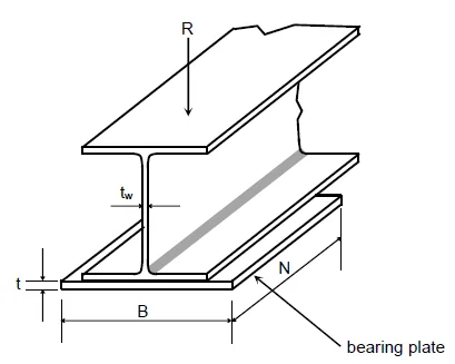
Designing the bearing plate involves finding its width $B$, length $N$, and thickness $t$ (see figure).
Step 1 — Choose $N$ to prevent web yielding and web crippling
Web yielding. Load spreads through the web at an approximate $1:2.5$ slope. The area in yielding and the nominal strength are:
• At a support:
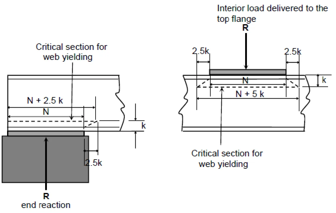
• At an interior load:
Design/allowable strengths:
Web Crippling
Buckling of the web caused by concentrated compression through the flange. Use the applicable web-crippling expressions (end reaction and interior reaction); select the case based on whether the load is near the end (within $d/2$) or interior.For a load at or near the support (within $d/2$ of the end):
• When $N/d \le 0.20$
• When $N/d > 0.20$
For an interior load, the nominal strength is:
For LRFD, $\phi = 0.75$ and for ASD, $\Omega = 2.00$.
Step 2 — Choose $B$ so concrete (or supporting material) does not crush in bearing
AISC bearing strength for concrete:
• Plate fully covering the support:
• Plate not covering the full support:
Where: $f'_c$ = concrete compressive strength;
$A_1$ = bearing area under the plate;
$A_2$ = area of the support geometrically similar and concentric with $A_1$.
Design/allowable:
Step 3 — Choose thickness $t$ for plate bending strength
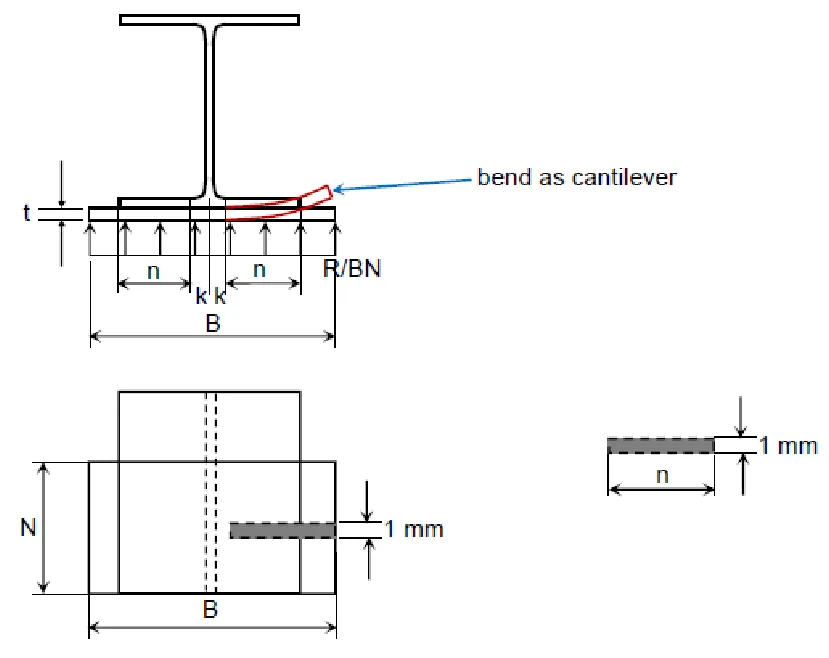
Treat a $1\,$mm strip of plate as a cantilever of span $n$ (see figure). With uniform pressure $R/(B N)$, the strip bending moment is:
Plastic moment capacity of a rectangular strip of thickness $t$:
LRFD thickness. Equate $M_u=\phi_b M_p$ with $\phi_b=0.90$ and solve for $t$:
ASD thickness. Equate $M_p/\Omega_b = M_a$ with $\Omega_b=1.67$ and solve for $t$:
Symbols:
$B$ = plate width;
$N$ = plate length (load length);
$t$ = plate thickness;
$t_w$ = web thickness;
$k$ = fillet distance from flange face to web toe;
$d$ = beam depth;
$R_u, R_a$ = factored/allowable reaction;
$F_y$ = steel yield stress;
$E$ = modulus of elasticity;
$\phi, \Omega$ = resistance/safety factors.


