$N$ = total number of piles; $A$ = pile area (taken as 1); $x$ or $y$ = location of pile from axis; $d$ = pile distance from neutral axis.
Pile cap shear and moment:
Critical section for one-way shear is at distance $d$ from the column face: $V_u = \Sigma R$ on the outside.
Critical section for two-way shear is $d/2$ from the column face: $V_u = P_u - R_{inside}$.
Critical section for moment is at the column face: $M = \Sigma R\,(d_i)$.
Pile-cap design requirements (NSCP):
Minimum pile spacing: 0.90 m (concrete piles); 0.76 m (timber/steel H-piles).
Pile embedment in cap: 150 mm minimum.
Minimum edge distance of pile: 450 mm from nearest concrete surface.
Minimum clear cover to reinforcement: 75 mm above pile tip embedded in footing.
Depth above bottom reinforcement: $\ge 300$ mm for pile-cap footings.
Analysis assumptions (pile caps):
Factored moments & shears use the pile reaction concentrated at the pile section centroid.
Entire reaction of a pile with center $\ge d_{pile}/2$ outside the section produces shear at that section.
Reactions of piles with center $\ge d_{pile}/2$ inside the section produce no shear at that section.
For intermediate positions, use linear interpolation between full value (outside) and zero (inside).
Reinforced Concrete Footings
Footings spread column or wall loads into the soil so that the factored soil pressure, shear, and flexural demand remain within safe limits. In board exam problems, the usual isolated footing checks are soil pressure, wide beam shear, punching shear, critical moment, and bottom reinforcement as a singly reinforced slab strip.
Use factored loads for strength design. For a concentric isolated footing with plan dimensions $B$ by $L$:
$$q_u=\frac{P_u}{BL}$$
$$q_{net,u}=q_u-\gamma_c h-\gamma_s h_s \quad \text{when the problem asks for net upward pressure}$$
Most RC footing problems use the upward factored soil pressure $q_u$ as the load on the footing slab. Confirm whether the given soil pressure is service, net service, gross service, or already factored.
Wide Beam Shear: One-Way Action and Diagonal Tension
Wide beam shear is the one-way shear check of the footing slab. The critical section is a vertical plane located a distance $d$ from the face of the column, pedestal, or wall. The shear crack is treated as diagonal tension, similar to beam action across the full footing width.
Here $b_w$ is the width of the resisting section, usually the full footing width perpendicular to the shear span. Use consistent units: if $f'_c$ is in MPa and dimensions are in mm, $V_c$ is in N.
Punching Shear: Two-Way Action
Punching shear checks whether the column tends to punch through the footing. The critical perimeter is located at $d/2$ from the face of the loaded area. For an interior rectangular column with dimensions $c_1$ and $c_2$:
Use $\beta_c$ as the ratio of long side to short side of the column. For $\alpha_s$, common values are 40 for interior columns, 30 for edge columns, and 20 for corner columns. In many board problems, the simple $0.33\lambda\sqrt{f'_c}b_od$ limit controls or is the only limit requested.
Critical Moment at the Column Face
The critical flexural section for an isolated footing is at the face of the column, pedestal, or wall. Treat each side of the footing projection as a cantilever loaded by upward soil pressure.
$$m_u=\frac{q_ul^2}{2} \quad \text{per unit strip width}$$
The larger moment usually controls the required effective depth and reinforcement. Check the direction of the bars: bars resisting moment from projection $l_x$ are placed perpendicular to that projection.
Design as a Singly Reinforced Section
A footing slab is normally designed as a singly reinforced rectangular section because tension steel is placed near the bottom and compression is carried by concrete above the neutral axis.
After selecting bars, compute spacing by $s=A_b(1000)/A_s$ for a 1-m strip. Also check clear cover, bar spacing, development length past the critical section, and whether the required bars fit within the footing width.
Pile Footing Reactions
For pile-supported footings, distribute the factored axial load and moment to the piles before checking beam shear, punching shear, and flexural moment. Let $n$ be the number of piles. If all piles have the same size and stiffness, the pile area is uniform and cancels out of the reaction formula, so the pile-group inertia can be computed using only pile distances and number of piles.
$$R_{avg}=\frac{P_u}{n}$$
$$I_x=\sum y_i^2 \quad \text{for moment about the } x\text{-axis}$$
$$I_y=\sum x_i^2 \quad \text{for moment about the } y\text{-axis}$$
Here $x_i$ and $y_i$ are pile distances from the centroidal axes of the pile group. If pile area $A_p$ is shown in a derivation, $I=A_p\sum d_i^2$ and the force increment is $M(A_pc)/I$, which simplifies to $Mc/\sum d_i^2$ for uniform piles.
$$R_i=\frac{P_u}{n}\pm\frac{M_x y_i}{I_x} \quad \text{for moment about the } x\text{-axis}$$
$$R_i=\frac{P_u}{n}\pm\frac{M_y x_i}{I_y} \quad \text{for moment about the } y\text{-axis}$$
$$R_i=\frac{P_u}{n}\pm\frac{M_x y_i}{I_x}\pm\frac{M_y x_i}{I_y} \quad \text{for biaxial moment}$$
$R_{max}$ is the reaction of the pile or pile row on the compressive side of the moment. $R_{min}$ corresponds to the farthest pile or pile row on the tension side, where the moment reduces compression and may cause uplift if the result becomes negative.
$$R_{max}=\frac{P_u}{n}+\frac{M_uc}{I}$$
$$R_{min}=\frac{P_u}{n}-\frac{M_uc}{I}$$
$$R_{mid}=\frac{P_u}{n} \quad \text{for piles on the centroidal axis of bending}$$
Board-Exam-Style Reminders
Use service loads for soil bearing size unless the problem gives a factored bearing pressure or asks directly for strength checks.
Use factored loads and factored soil pressure for shear and moment design.
One-way shear is checked at $d$ from the column face; punching shear is checked at $d/2$ from the column face.
Critical moment is at the column face, not at $d$ or $d/2$.
Increasing footing thickness increases $d$, which helps both one-way and punching shear.
Footing flexural steel is bottom steel because the upward soil pressure causes tension at the bottom near the column face.
Do not mix meters and millimeters in the same formula. Convert moments to N-mm when using MPa and mm.
Sample Design of an Isolated Footing
A square tied column carries a factored axial load $P_u=1800$ kN. The column is $400 \text{ mm} \times 400 \text{ mm}$ and is supported by a $2.4 \text{ m} \times 2.4 \text{ m}$ square footing. Use $f'_c=28$ MPa, $f_y=420$ MPa, normal-weight concrete, $h=550$ mm, effective depth $d=460$ mm, and $\phi=0.75$ for shear, $\phi=0.90$ for flexure. Check shear and find the required bottom steel per meter strip.
Minimum steel controls. Provide at least $990\text{ mm}^2/\text{m}$ each way at the bottom. For 16 mm bars, $A_b=201\text{ mm}^2$ and $s=201(1000)/990=203$ mm, so use 16 mm bars at 200 mm on center each way, subject to development length and detailing checks.
Eccentric Footing Soil Pressure and Resultant
A footing has dimensions $B \times L \times H=3\text{ m}\times4\text{ m}\times0.75\text{ m}$. The column is $0.60\text{ m}\times0.75\text{ m}$. Earth fill above the footing is $1.5\text{ m}$, soil unit weight is $17\text{ kN/m}^3$, and concrete unit weight is $24\text{ kN/m}^3$. The service column loads are: dead load $880\text{ kN}$ with $48\text{ kN-m}$, live load $520\text{ kN}$ with $28\text{ kN-m}$, and earthquake load $140\text{ kN}$ with $180\text{ kN-m}$ about the $y$-axis. Determine the maximum soil pressure, minimum soil pressure, and location of the resultant from the end of the footing.
A rectangular footing is $2.5\text{ m}$ wide along the $y$-axis and $3\text{ m}$ long along the $x$-axis. It supports a circular pedestal $0.45\text{ m}$ in diameter. A horizontal force of $144\text{ kN}$ acts at the top of the pedestal. The total axial service load is $1200\text{ kN}$, footing thickness is $0.70\text{ m}$, backfill height above the footing is $1.5\text{ m}$, and the pedestal height from the footing base is $2.5\text{ m}$. Use $\gamma_c=24\text{ kN/m}^3$ and $\gamma_s=17\text{ kN/m}^3$. Find the maximum net soil pressure, minimum net soil pressure, and required gross bearing capacity.
A $2\text{ m}\times2\text{ m}$ footing carries a concentric $0.40\text{ m}\times0.40\text{ m}$ column. Factored column loads are $D=580\text{ kN}$ and $L=440\text{ kN}$. Cover to the centroid of footing reinforcement is $100\text{ mm}$, $f'_c=28\text{ MPa}$, and $f_y=415\text{ MPa}$. Allowable ultimate stresses are $1.76\text{ MPa}$ for diagonal tension or two-way action shear, $0.88\text{ MPa}$ for wide beam shear, and maximum steel ratio for moment is $0.021$. Determine the minimum footing thickness required for punching shear, wide beam shear, and moment.
Punching shear controls; use a footing thickness of about $361\text{ mm}$, rounded upward in design.
Allowable Axial Load and Required Bars
A $2\text{ m}\times2\text{ m}$ footing, $0.45\text{ m}$ thick, carries a centered $0.40\text{ m}\times0.40\text{ m}$ square column. Effective depth is $0.35\text{ m}$, $f'_c=28\text{ MPa}$, and $f_y=415\text{ MPa}$. Allowable stresses at ultimate loads are $1.76\text{ MPa}$ for two-way action shear and $0.88\text{ MPa}$ for wide beam shear. Determine the allowable axial load based on punching shear, the allowable axial load based on wide beam shear, and the number of 20 mm bars required if $M_u=300\text{ kN-m}$.
A footing supports a $250\text{ mm}$ thick concrete wall. Wall loads are $D=175\text{ kN/m}$ and $L=89\text{ kN/m}$. Use $f'_c=20.6\text{ MPa}$, $f_y=415\text{ MPa}$, concrete unit weight $23.6\text{ kN/m}^3$, and $U=1.2D+1.6L$. The footing width is $1.75\text{ m}$, footing thickness is $300\text{ mm}$, and cover to the centroid of reinforcement is $100\text{ mm}$. Find the required spacing of 16 mm bars due to moment, the wide beam shear stress, and the footing width if allowable soil pressure is $96\text{ kPa}$ with a $250\text{ mm}$ footing thickness.
Use a footing width of about $3.0\text{ m}$ for the service bearing check.
Pile-Supported Footing Thickness and Bars
A $400\text{ mm}\times400\text{ mm}$ column is supported by a square footing on 9 piles. Dimensions are $a=0.6\text{ m}$, $b=1.8\text{ m}$, and $d=0.6\text{ m}$. The column carries $D=900\text{ kN}$ and $L=450\text{ kN}$. Use $f'_c=21\text{ MPa}$, $f_y=415\text{ MPa}$, allowable beam shear stress $0.76\text{ MPa}$, allowable punching shear stress $1.52\text{ MPa}$, and minimum cover to centroid of reinforcement $0.25\text{ m}$. Determine required footing thickness for beam shear, required thickness for punching shear, and number of 20 mm bars required for maximum moment about the $x$-axis.
$$P_u=1.2(900)+1.6(450)=1800\text{ kN}$$
$$R=\frac{P_u}{9}=200\text{ kN per pile}$$
Use 14-20 mm bars. Punching shear controls the footing thickness.
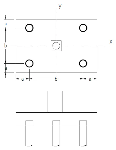
Problem: Square Footing with Piles
A 600mm x 600mm column is supported by a 3.6m square footing on 5 piles as shown.
Dimensions are as follows:
a=0.6m
b=2.40m
Effective depth = 650mm
Diameter of pile = 350mm
Ultimate pile capacity = 280kN
Column axial loads:
D=420kN
L=360kN
E=210kN
Column moment due to earthquake = 160kN-m about the y-axis
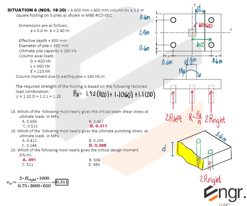
The required strength of the footing is based on the following factored load combination:
U=1.32D + 1.1L +1.1E
a. Determine the critical beam shear stress at ultimate loads in MPa.
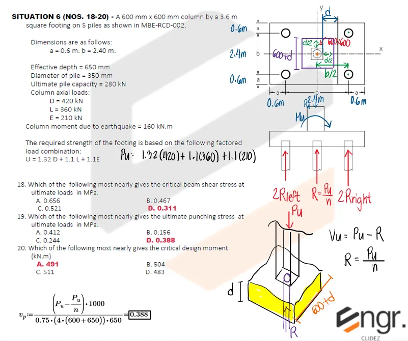
b. Determine the ultimate punching shear stress at ultimate loads in MPa.
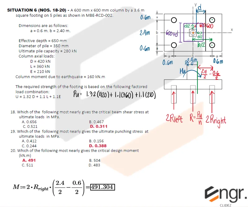
c. Determine the critical design moment in kN-m.
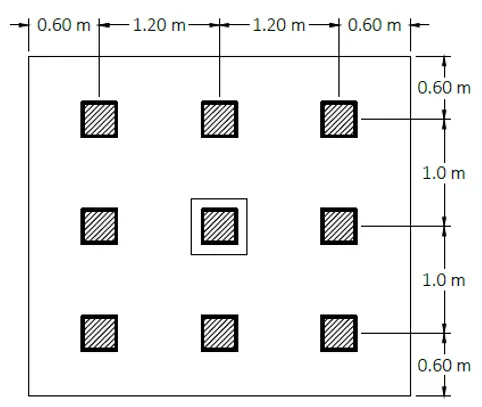
A pile footing supports a 600 mm-square column. The pile cap rests on 9 square precast concrete piles, each 350 mm by 350 mm, arranged as shown below. Capacity per pile at ultimate condition = 300 kN.
Allowable stresses and design data:
Wide beam shear stress = 0.88 MPa
Punching shear stress = 1.25 MPa
Concrete compressive stress, f'c = 24 MPa
Steel yield strength, fy = 413 MPa
Reduction factor for shear = 0.75
Reduction factor for moment = 0.90
Minimum concrete cover to the centroid of footing reinforcement = 250 mm
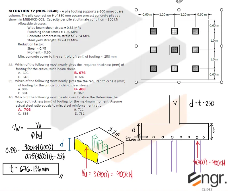
a. Which of the following most nearly gives the required thickness in mm of footing for the critical wide beam shear?
A. 696
B. 676
C. 648
D. 682
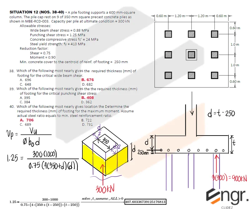
b. Which of the following most nearly gives the required thickness in mm of footing for the critical punching shear stress?
A. 395
B. 408
C. 384
D. 362
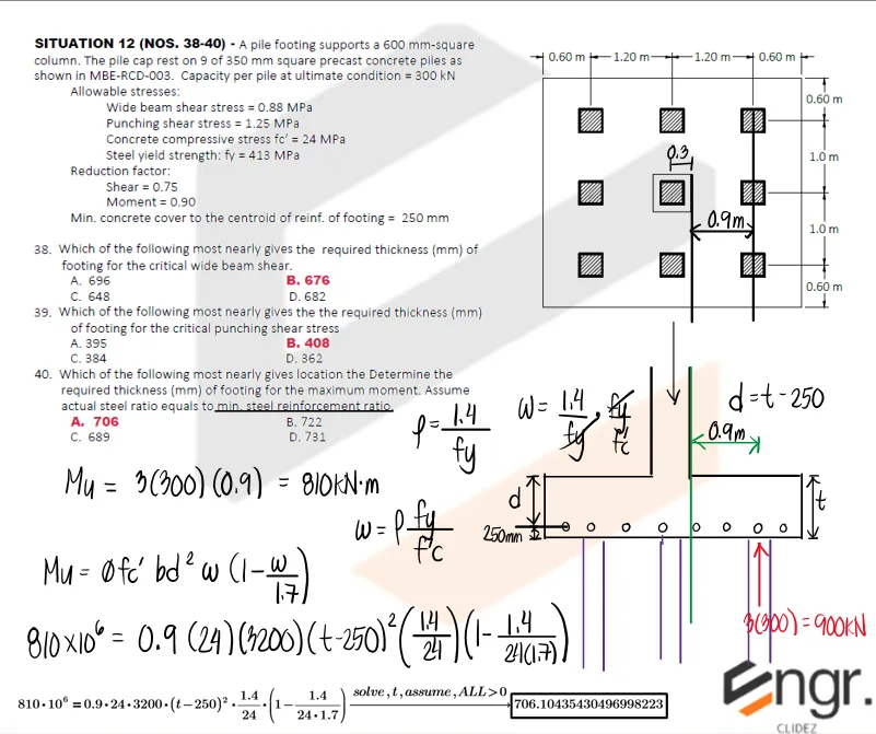
c. Which of the following most nearly gives the required thickness in mm of footing for the maximum moment? Assume actual steel ratio equals the minimum steel reinforcement ratio.
A. 706
B. 722
C. 689
D. 731
Use the effective depth relation d = t - 250 mm.
Wide beam shear: the critical section cuts off the three exterior piles, so Vu = 3(300) = 900 kN and b = 3200 mm.
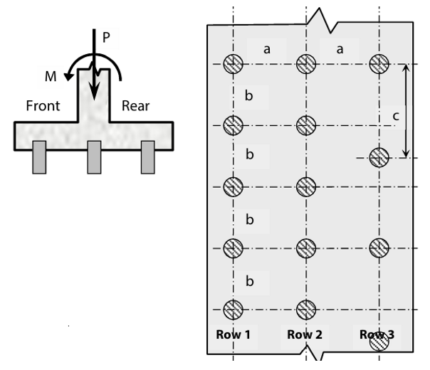
A continuous wall is founded on three rows of piles spaced a=1.8m apart. The longitudinal pile spacing is b=2m in the front and center rows and c=3m in the rear row. The resultant of vertical loads on the wall is P=950kN per linear meter and the resultant moment is M=265kN-m per linear meter.
A continuous wall is founded on three rows of piles spaced a=1.5m apart. The longitudinal pile spacing is b=1.8m in the front and center rows and c=2.7m in the rear row. The resultant of vertical loads on the wall is P=750kN per linear meter and the resultant moment is M=225kN-m per linear meter.