CECC-483 Reference Formula Sheet — Reinforced Concrete Columns
Complete column formula list (tied, spiral, eccentrically loaded, and slender) per the CECC-483 / NSCP review notes.
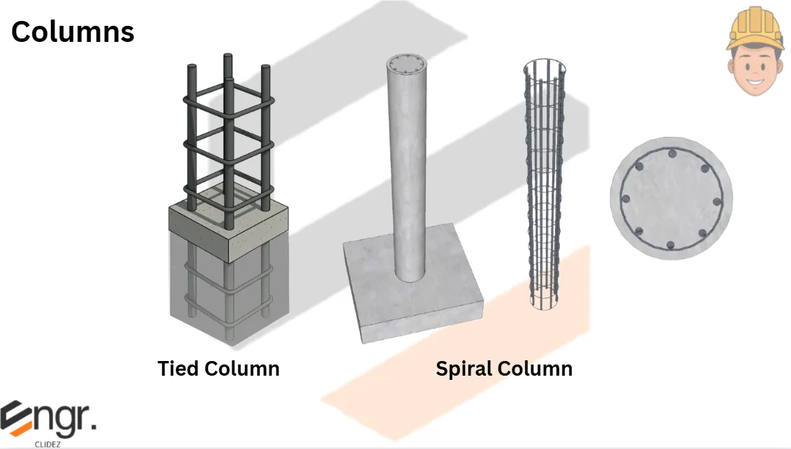
Classification of columns:
According to reinforcement: tied or spiral.
According to slenderness: short ($KL_u/r \le 34-12 M_1/M_2$) or slender.
According to load: axially loaded; eccentrically loaded (uniaxial or biaxial bending).
According to section: square/rectangular; round/circular.
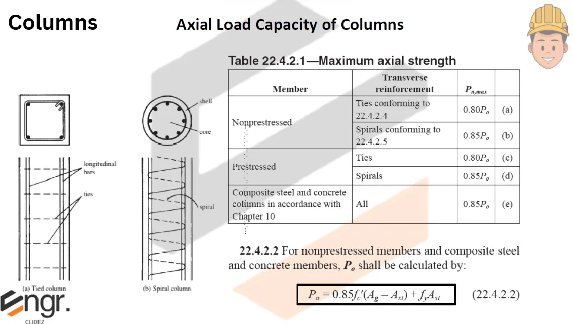
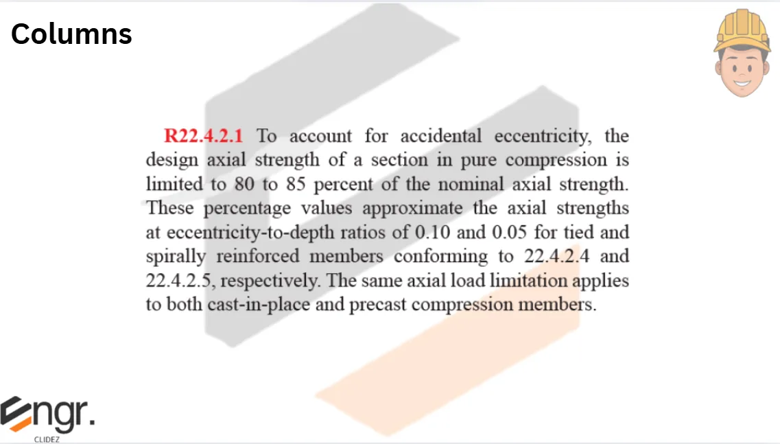
Axially loaded resistance (short columns):
$$P_u = 0.80\,\phi\,A_g\!\left[0.85f'_c(1-\rho_g)+\rho_g f_y\right]\quad\text{(tied, }\phi=0.65\text{)}$$
$$P_u = 0.85\,\phi\,A_g\!\left[0.85f'_c(1-\rho_g)+\rho_g f_y\right]\quad\text{(spiral, }\phi=0.70\text{ or 0.75 by NSCP 2015)}$$
$$P_u = \phi\,0.80\,A_g\!\left[0.85f'_c(A_g-A_{st}) + A_{st}f_y\right]\quad\text{(tied, alternative form)}$$
ACI code specs:
Tied: $\rho_g = 0.01-0.08$; min 4-16 mmφ bars (rec.) or 6-16 mmφ (round); min ties 10 mmφ (32 mmφ main or less) or 12 mmφ (greater than 32 mmφ main); tie spacing = smallest of $16d_b$, $48d_t$, least column dimension.
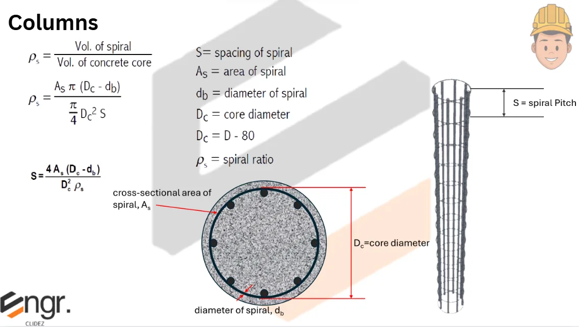
Spiral: $\rho_g = 0.01-0.08$; min diameter 250 mm; main bars min 6-16 mmφ; spiral min 10 mmφ; clear distance between vertical bars $\ge 1.5d_b$ or $1.5\times$max aggregate; spiral pitch between 25 and 75 mm and not more than $D_c/6$.
Slenderness can be ignored if $KL_u/r \le 34 - 12 M_1/M_2$ for braced (non-sway) frames; $KL_u/r \le 22$ for unbraced columns. $M_1/M_2$ is negative for single-curvature and positive for reverse-curvature bending.
Steps in solving slender columns:
Check slenderness: $KL_u/r > 34-12 M_1/M_2$ ?
Compute $E_c = 4700\sqrt{f'_c}$.
Compute $I_g = bh^3/12$.
Compute $\beta_d$.
Compute $EI$.
Compute $P_c$.
Compute $C_m$.
Compute $\delta_b$.
Compute the magnified moment $M_c = \delta\,M_u$.
Compute the magnified eccentricity $e = M_u / P_u$ and compare with $e_{min}$.
Reinforced Concrete Columns
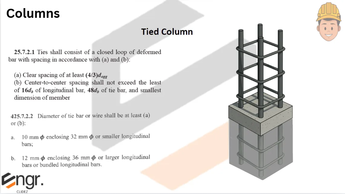
ACI Code Specifications: Tied Column:
\(\rho_g=0.01-0.08\)
Minimum Reinforcement:
4-16mm\(\phi\) for square or rectangular column
6-16mm\(\phi\) for round tied column
Minimum Gross Area Ag=60,000mm2 or 250mmx250mm
Lateral Ties:
10mm\(\phi\) for 32mm\(\phi\) or smaller vertical bars
12mm\(\phi\) for vertical bars greater than 32mm\(\phi\)
Spacing of Lateral Ties (choose least):
16db (main bars)
48dt (tie bar)
least column dimension
When there are more than four vertical bars, additional ties shall be provided so that no longitudinal bar shall be spaced more than 150mm on each side.
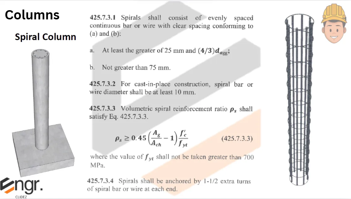
Spiral Column:
\(\rho_g=0.01-0.08\)
Minimum Reinforcement: - 6-16mm\(\phi\)
Spacing of spirals: 25mm\(\le\)S\(\le\)75mm
Minimum spiral diameter: 10mm\(\phi\)
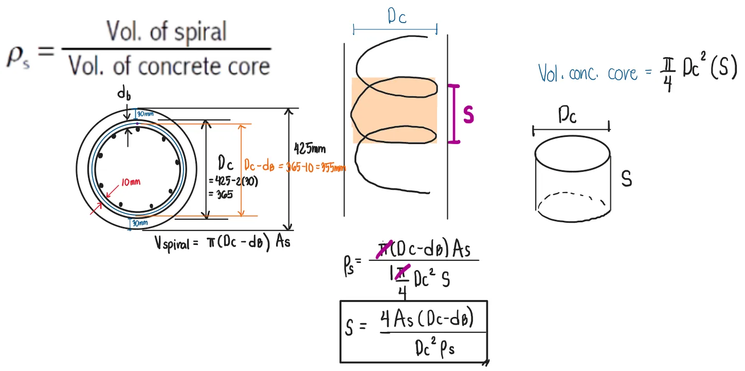
\(\rho_s=\) ratio of the volume of spiral reinforcement to the volume of concrete core
Ag=gross area of column
Ach=cross-sectional area of concrete core
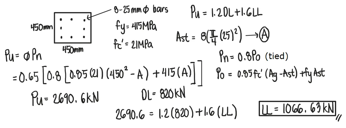
Problem (Investigation):
A square tied column 450mm on each side is reinforced with 8-25mm bars with fy=415MPa. Determine the safe service axial live load if the axial dead load on the column is 820kN. Use f'c=21MPa.
See images:
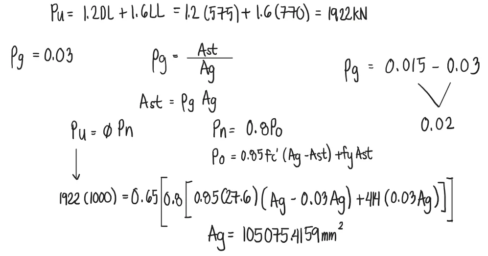
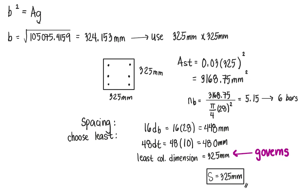
Problem (Design):
Design a square tied column that must support an axial dead load of 575kN and an axial live load of 770kN. Assume f'c = 27.6MPa and fy=414MPa. Use 28mm main bars and 10mm ties.
See images:
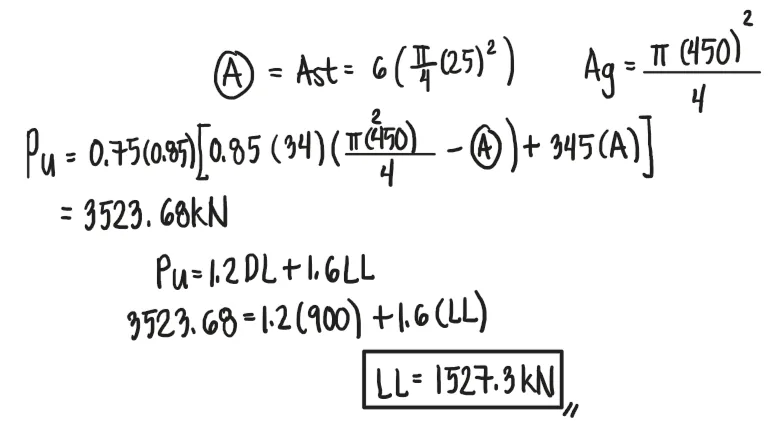
Problem (Investigation):
A round spiral column having a diameter of 450mm is reinforced with six 25mm bars with fy=345MPa. If the service axial dead load is 900kN, determine the safe axial live load of the column. Use f'c=34MPa.
See images:
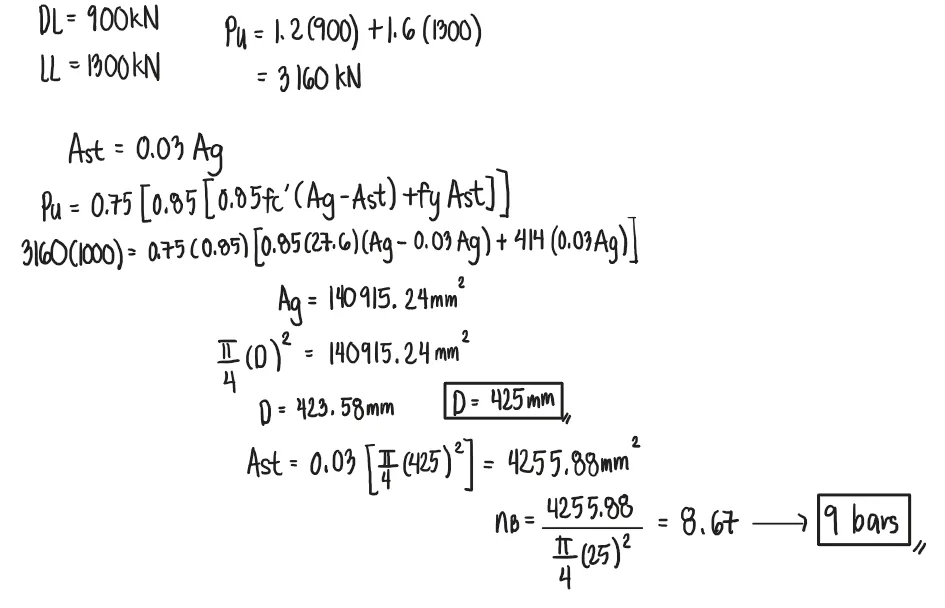
Problem (Design):
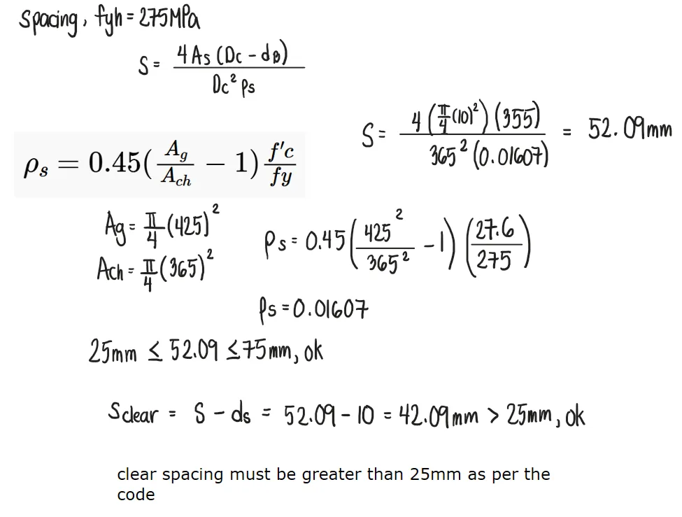
Design a round spiral column to support an axial dead load of 900kN and an axial live load of 1300kN. Assume that 3% longitudinal steel is desired, f'c=27.6MPa, and fy=414MPa. Use 25-mm main reinforcement. Determine also the minimum spacing of 10-mm spiral (fyh=275MPa) with 30mm steel covering.
See images:
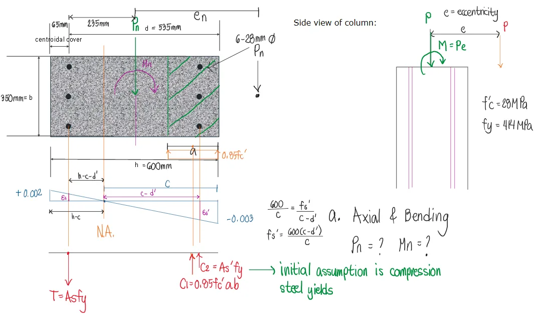
Problem:
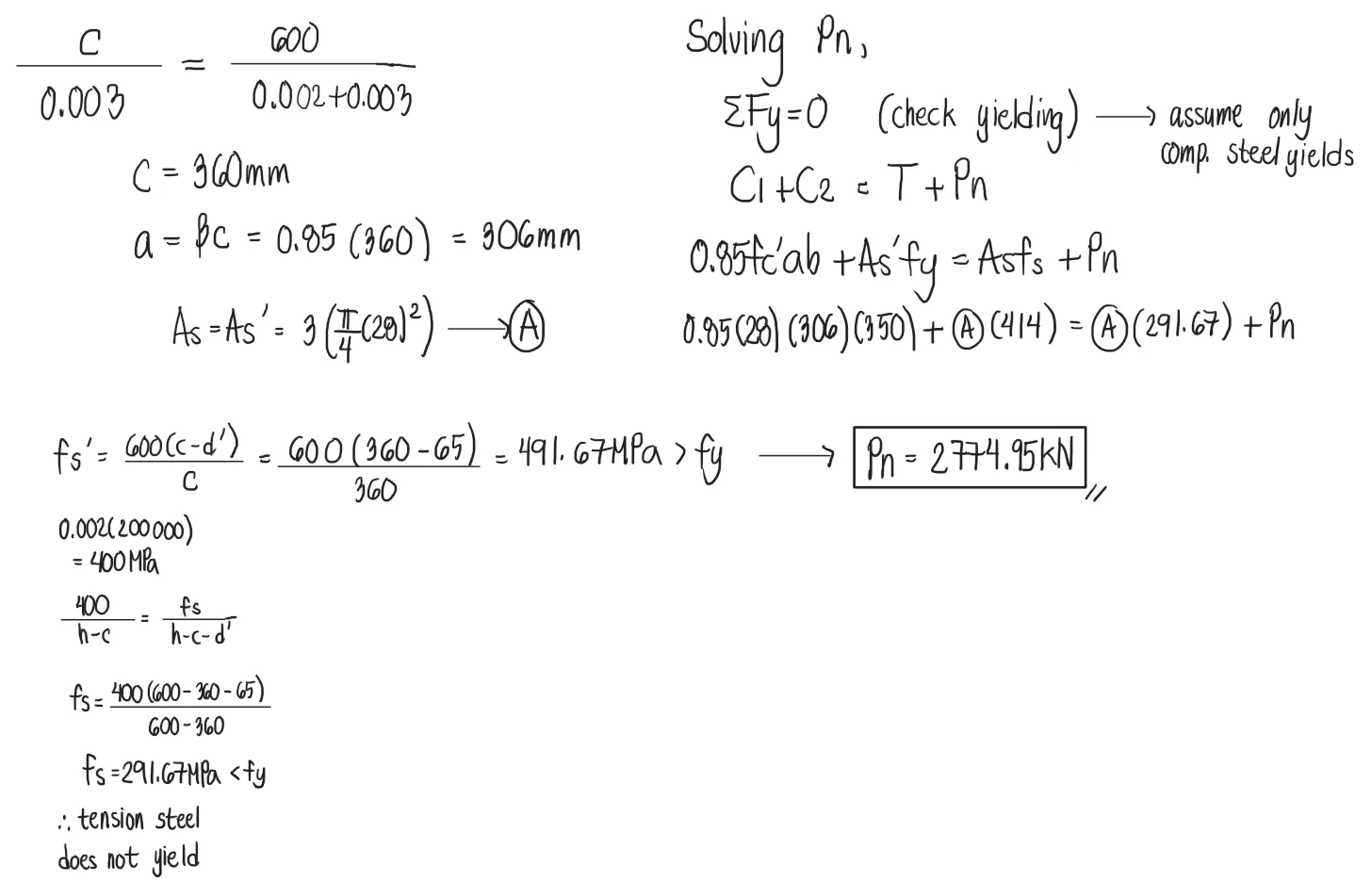
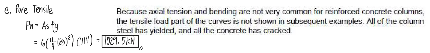
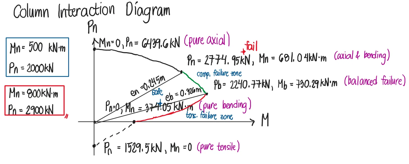
The column in the figure shown below has a strain on its compressive edge equal to -0.003 and has a tensile strain of +0.002 on its other edge. It is reinforced with 6-28mm bars. b=350mm and h=600mm. Steel covering to the centroid of reinforcement is 65mm. Determine the nominal values of Pn and Mn that cause this strain distribution if f'c=28MPa and fy=414MPa.
See images:
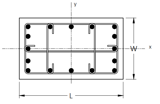
Problem: Shear in Concrete Columns along x and y Axes
Refer to the figure shown below.
Given:
Column dimension, W x L = 400 mm x 600 mm
Main reinforcement, Ast = 10-25 mmØ
Ties of hoop reinforcement = 12 mmØ spaced at 100 mm O.C.
Steel yield strength = 415 MPa
Concrete compressive strength = 28 MPa
Concrete clear cover = 40 mm
Permissible concrete shear stress = 0.82 MPa
a. Which of the following most nearly gives the nominal axial load strength (in kilonewtons) of the column, Pn?
b. Which of the following most nearly gives the nominal shear capacity of the section along the x-direction?
c. Which of the following most nearly gives the nominal shear capacity of the section along the y-direction?
See images:
Problem: CE Board May 2013 & Nov. 2012 — Bar Substitution
A column is to be reinforced with 8 – 28 mm ∅ bars. If 25 mm ∅ bars are used instead, how many bars are needed if the column reinforcement has to be equal on all four sides?
Problem: CE Board May 2016 — Rectangular Tied Column Design
An axially loaded rectangular tied column is to be designed for the following service loads:
Dead load = 1600 kN | Live load = 845 kN
Required strength: U = 1.2DL + 1.6LL | φ = 0.65
Effective cover to centroid of reinforcement = 70 mm
f'c = 27.5 MPa | fy = 415 MPa
Using 3% vertical steel ratio, what is the required column width (mm) if architectural considerations limit the width in one direction to 400 mm?
For a column section 400 mm × 500 mm, what is the minimum design moment (kN·m) about the stronger axis?
For a 400 mm × 500 mm column section with 16 bars and ρ = 3%, find the required bar diameter.
Problem: CE Board Nov. 2015 — Spiral Column (Slenderness & Bar Count)
A spiral column 600 mm in diameter has an unsupported height of 2.4 m. The column is bent in single curvature and is braced against sidesway.
Service loads: DL = 3200 kN, LL = 1420 kN | Required strength: U = 1.2D + 1.6L
f'c = 27.5 MPa | fy = 413 MPa
What is the slenderness ratio of the column? (Assume pinned ends, k = 1.0)
If the required steel ratio is 1.7%, find the number of 32 mm ∅ bars.
Find the number of 32 mm ∅ bars required at the ultimate design load (U = 1.2D + 1.6L).
Given:
Column: b × h = 600 mm × 450 mm | Main reinforcement: 8 – 28 mm ∅ bars
Lateral ties = 10 mm ∅ at 100 mm o.c. | fy = 415 MPa | fyv = 275 MPa
f'c = 28 MPa | Ec = 25,000 MPa | Clear cover to centroid of main bars = 70 mm
Unsupported height Lu = 2.5 m | Effective length factor K = 1.0
What is the nominal axial strength Pn of the column (kN)?
Find the critical buckling load Pc (kN).
Calculate the nominal shear strength Vn for bending about the y-axis.
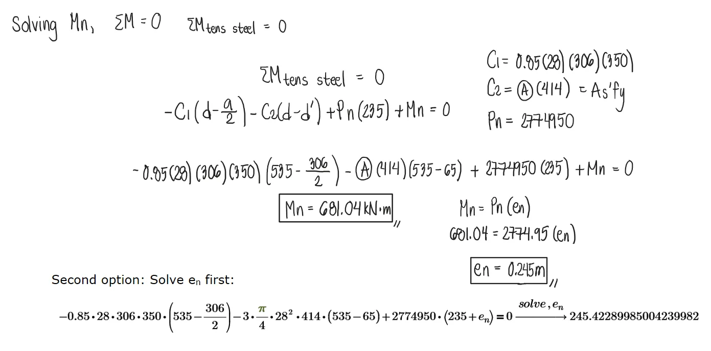
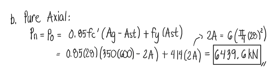
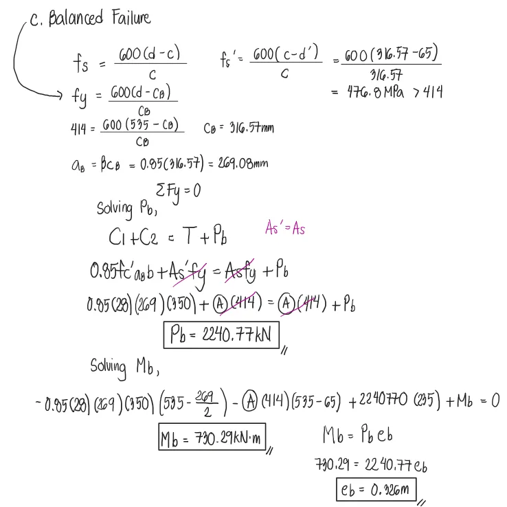
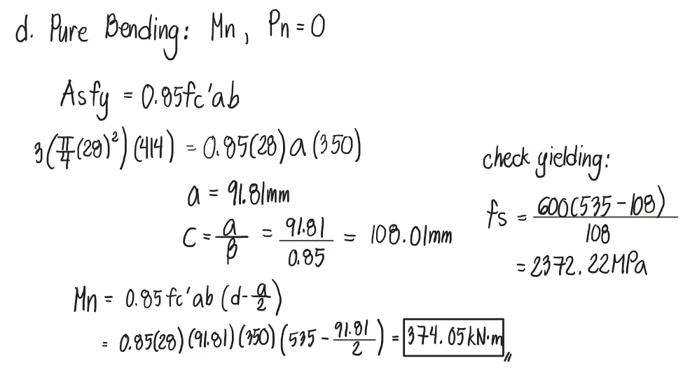
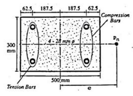
A tied column which is subjected to an eccentric load has dimensions of 300mmx500mm which is reinforced with 4-28mm⌀ bars arranged as shown in the figure. The concrete cylinder strength f'c=27.6MPa and the stee yield strength fy=414.7MPa. The column carries a nominal load Pn at an eccentricity e from the y-axis of the column section. If the neutral axis is 125mm from the right edge of the column section and neglecting the area of concrete displaced by the compression steel bar,
Determine the value of the nominal load Pn assuming that the compression steel will not yield.
607
706
504
405
Compute the nominal moment capacity of the column section.
312.25
506.22
447.74
392.01
Determine the eccentricity where the nominal load Pn is acting.
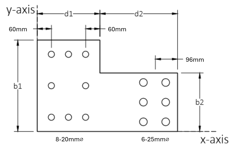
The section of a column is shown. d1=320mm, d2=510mm,b1=400mm, b2=260mm. f'c=20.7MPa and fy=415MPa.
Determine the location of the centroid of the gross concrete area measured from the y-axis in mm.
371.2
354.9
320.6
402.3
Determine the location of the plastic section (in mm) of the column measured from the y-axis. Neglect the area of concrete displaced by the steel.
403.75
395.7
326.8
311.1
Determine the factored moment Mux (in kN-m) due to a factored load Pu=5200kN applied 425mm from the y-axis and 190mm from the x-axis. Assume that the column is reinforced such that the plastic centroid is 400mm from the y-axis and 160mm from the x-axis.
A spiral column carries a gravity factored axial dead load of 1200kN and factored axial lived load of 2100kN. The column is of average height and it will be assumed that there is no reduction in strength due to the effects of slenderness. Use approximately 1.5% reinforcement. Using f'c=27.6MPa and fy=415MPa,
Determine the required diameter of the spiral column.
450
400
420
430
Determine the number of 28-mm diameter bar longitudinal bars.
6
7
8
5
Determine the practical center to center spacing of 10-mm diameter spiral reinforcement.
CE Board May 2022 A tied column 450mmx450mm is reinforced with 8-28 mm bars equally distributed on its sides. The unsupported length of the column is 2.6m and is prevented to sidesway due to shear walls. K=1.0, f'c=20.7MPa, and fy=415MPa. Use 40mm covering measured from the center of reinfocement. The diameter is 12mm. Es=200GPa.
Determine the nominal load that the column could carry.
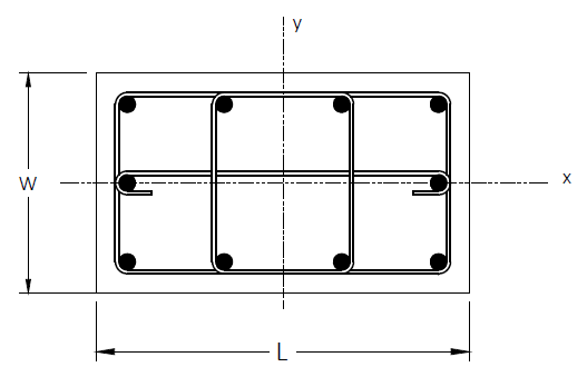
Refer to the column section shown.
W x L = 600 mm x 800 mm
Main reinforcement Ast = 16 – 25 mm diameter bars
Lateral ties = 10 mm diameter bars
Reinforcing steel yield strength:
Main reinforcement, fy = 415 MPa
Lateral ties, fyv = 275 MPa
Concrete, fc’ = 28 MPa
Clear concrete cover = 40 mm
Spacing of ties = 150 mm
Which of the following most nearly gives the nominal shear strength (in
kN) of the column for the shear parallel to the x-axis?
717
833
912
878
Which of the following most nearly gives the nominal shear strength (in
kN) of the column for the shear parallel to the y-axis?
833
912
717
878
Which of the following nearly gives the the nominal compressive load (in
kN) at zero eccentricity?