CECC-483 Reference Formula Sheet — T-Beams (NSCP 2015)
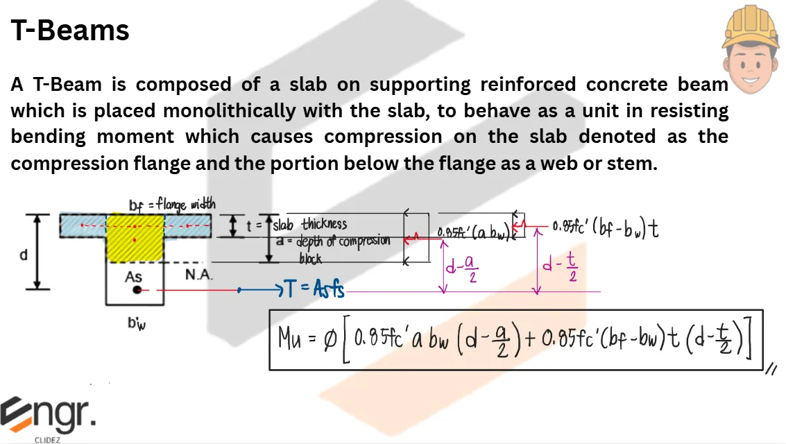
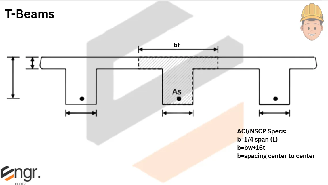
T-Beam analysis & design procedures from the CECC-483 review notes. Reinforced concrete floor systems usually consist of slabs and beams cast monolithically; the beams gain flanges from the adjacent slabs.
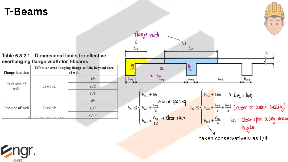
Dimensional limits for effective overhanging flange width (NSCP 2015):
Flange Location
Effective overhanging flange width beyond face of web (least of)
Each side of the web (interior T-Beam)
$8h$; $S_w/2$; $L_n/8$
One side of the web (L-Beam / spandrel)
$6h$; $S_w/2$; $L_n/12$
where $L_n$ = clear distance between column supports, $S_w$ = clear web spacing.
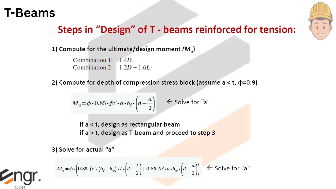
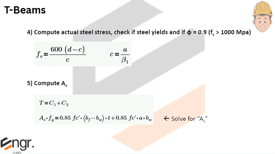
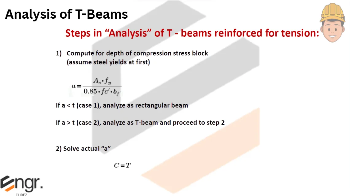
Steps in determining the tension steel As of a T-Beam given Mu:
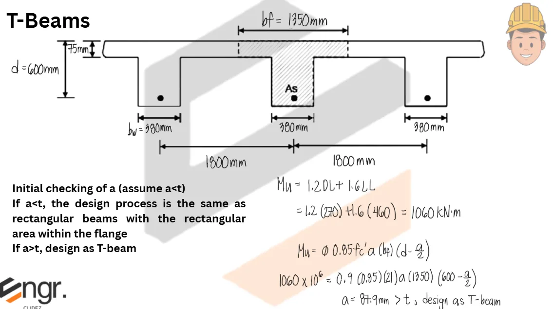
Assume the entire flange is in compression and solve for $M_{u1}$:
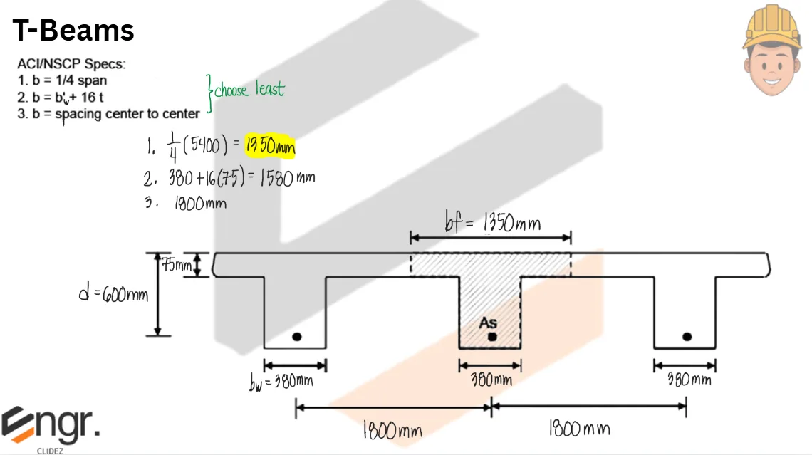
$$b_f=\min(b_{f1},b_{f2},b_{f3})$$
$$b_{f1}=b_w+16t_s,\qquad b_{f2}=S,\qquad b_{f3}=\frac{L}{4}\text{ or }b_w+\frac{L}{4}\text{ as used by the given notes}$$
$$M_u=1.2M_D+1.6M_L,\qquad M_n=\frac{M_u}{\phi}$$
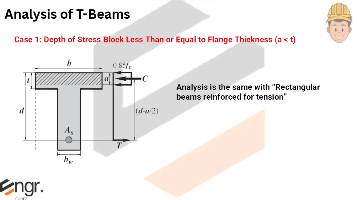
$$M_n=0.85f'_c b_f a\left(d-\frac{a}{2}\right)\quad \text{if }a\leq t_s$$
$$a=d-\sqrt{d^2-\frac{2M_n}{0.85f'_c b_f}}$$
$$A_s=\frac{0.85f'_c b_f a}{f_y}$$
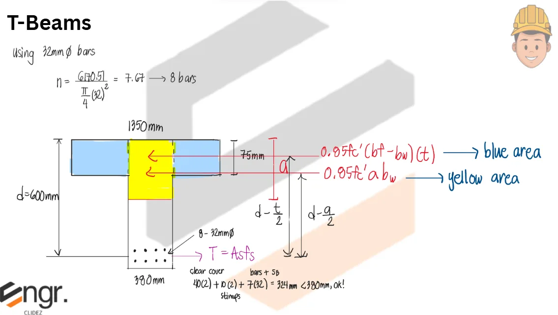
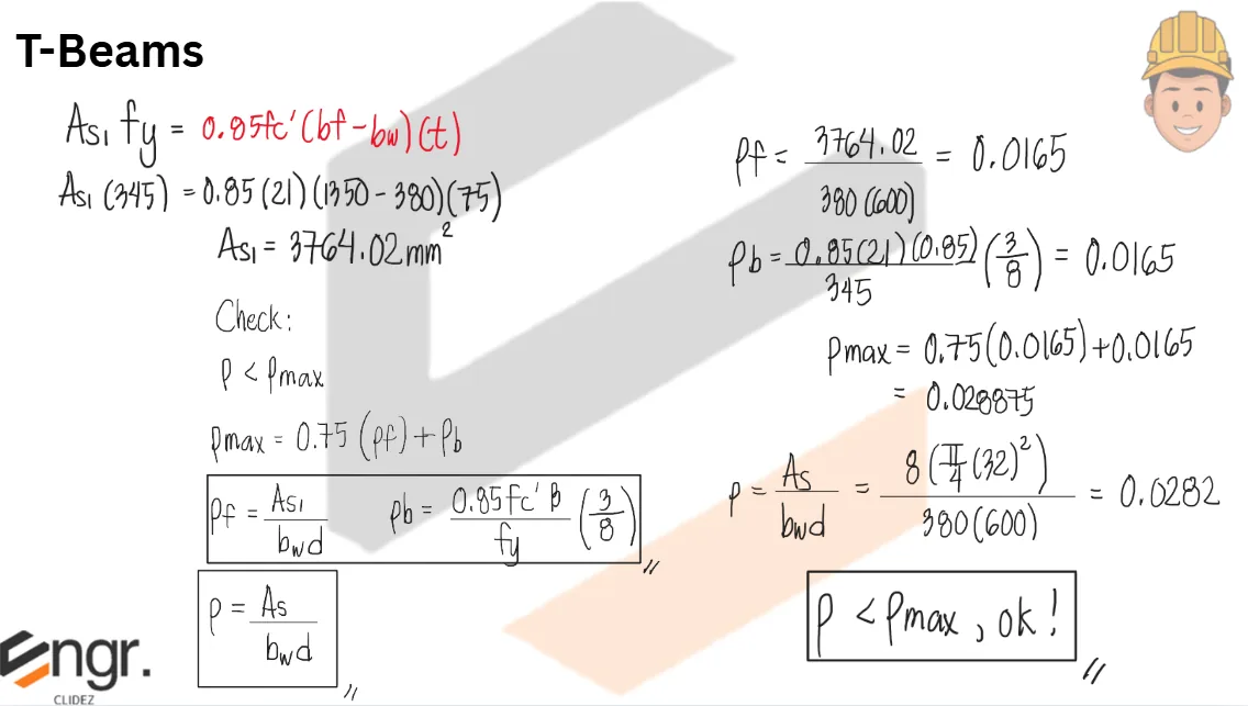
Design a T-beam for the floor system shown. Thickness of slab is 75mm and width of web is 380mm. The beam carries a dead load moment of 270kN-m and a live load moment of 460kN-m. The beam has a span of 5.4m and has a spacing center to center of 1.8m. Use f'c=21MPa and fy=345MPa. The effective depth is 600mm
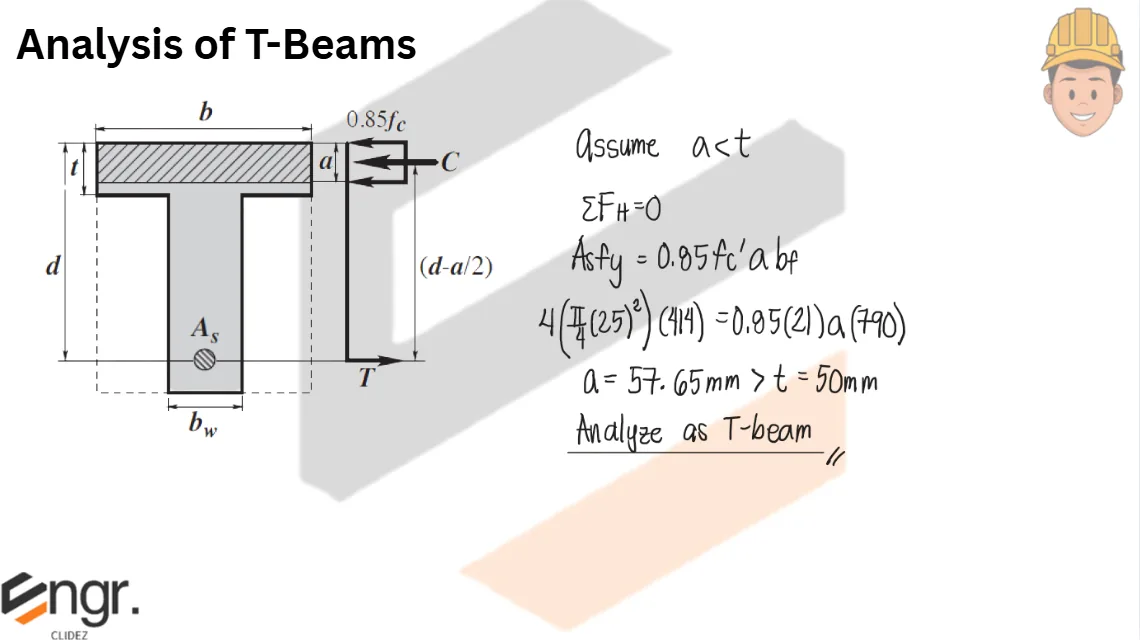
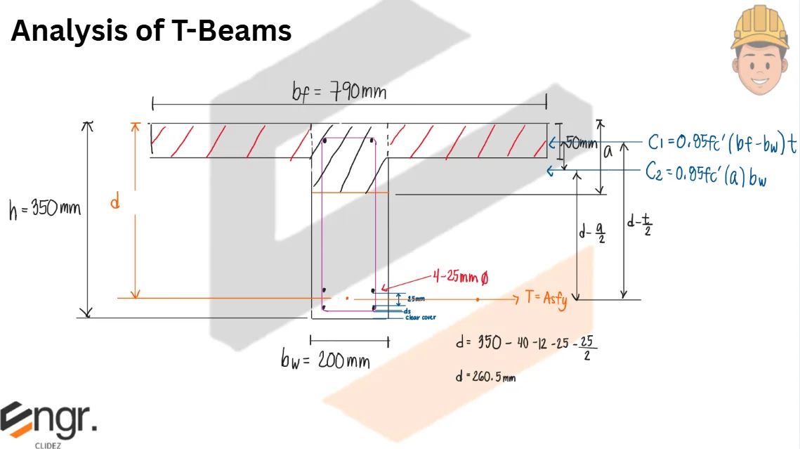
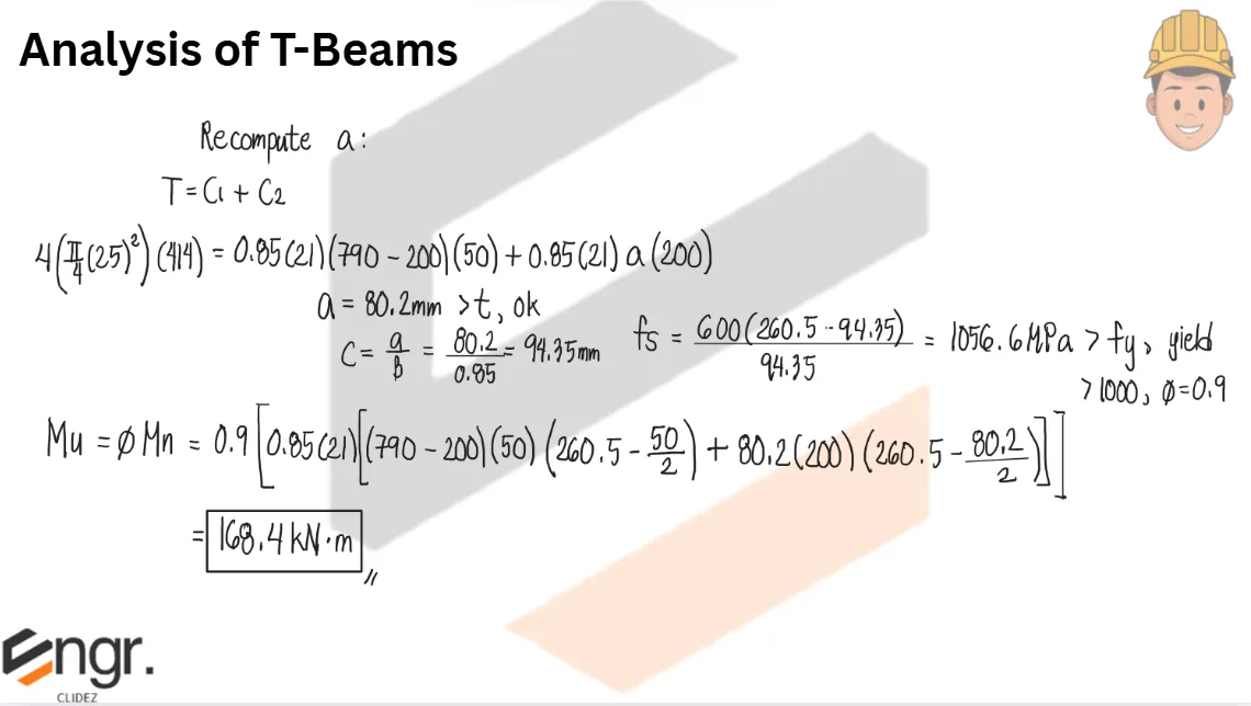
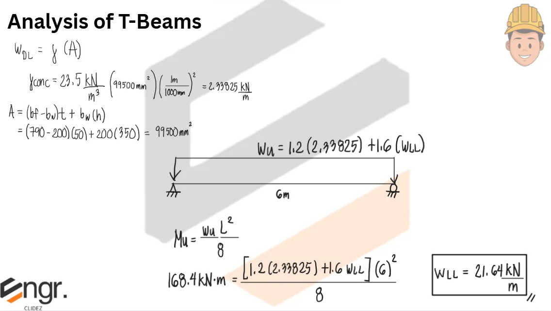
Find the safe live load that a T-beam section with a flange width of 790mm and a beam width of 200mm can carry if it has a simple span of 6m. The beam is reinforced with 4-25mm diameter bars placed in two layers. Use f'c=21MPa and fy=414MPa. The total height of the beam is 350mm. Assume diameter of stirrups is 12mm. The slab thickness is 50mm. While anchor bars are needed to keep the stirrups in place, neglect it in the calculation.
See images:
CE Board 1986: T-Beam from Service Moments
A reinforced concrete T-beam has slab thickness $t_s=100\text{ mm}$, total depth $h=550\text{ mm}$, web width $b_w=300\text{ mm}$, and effective cover to the tension steel of $65\text{ mm}$. The beam has a simple span of $L=6\text{ m}$ and beam spacing $S=2.4\text{ m}$ center to center. It carries service moments $M_D=84\text{ kN-m}$ and $M_L=184\text{ kN-m}$. Use $f'_c=20.7\text{ MPa}$ and $f_y=413.7\text{ MPa}$.
Determine the effective flange width.
Determine the depth of the compression block.
Determine the required tension steel area.
Use the least value from the effective flange width limits:
A reinforced concrete T-beam has effective depth $d=600\text{ mm}$ and is reinforced with 8-28 mm diameter bars in two layers. The web width is $b_w=300\text{ mm}$ and the flange thickness is $t_s=90\text{ mm}$. Use $f'_c=21\text{ MPa}$ and $f_y=415\text{ MPa}$. The beam has a simple span of $5.8\text{ m}$ and beam spacing of $1.5\text{ m}$ on center.
Calculate the effective flange width.
Calculate the depth of the rectangular stress block.
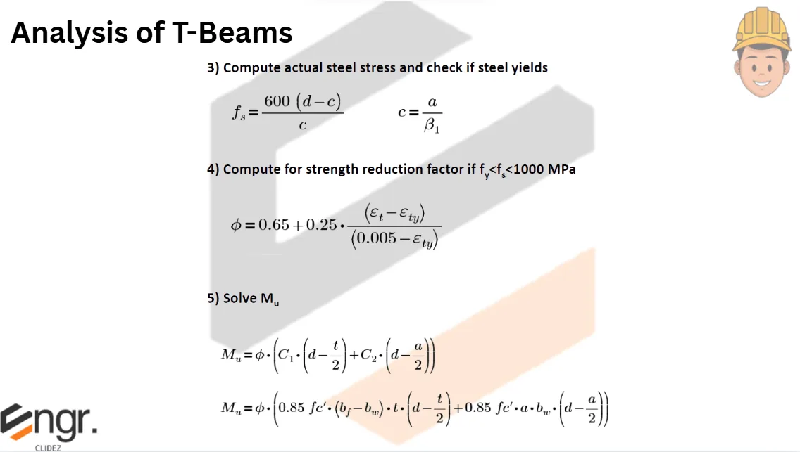
Calculate the nominal moment capacity of the beam.
Use the effective flange width checks and the total steel area:
A T-beam has flange width $b_f=0.70\text{ m}$, web width $b_w=0.35\text{ m}$, slab thickness $t_s=100\text{ mm}$, and effective depth $d=450\text{ mm}$. It is reinforced with tension steel area $A_s=2925\text{ mm}^2$. Use $f'_c=17.24\text{ MPa}$ and $f_y=413.7\text{ MPa}$. The simple span is $6\text{ m}$ and the total service dead load including beam weight is $20\text{ kN/m}$.
Determine the depth of the stress block.
Determine the ultimate moment capacity of the beam.
Determine the safe concentrated service live load at midspan.
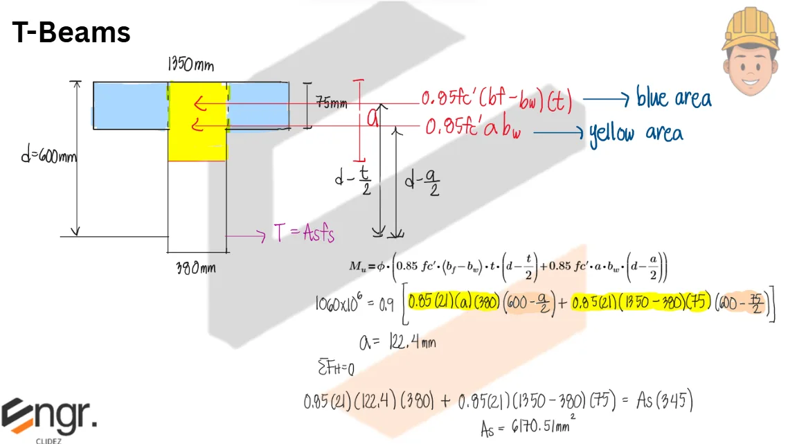
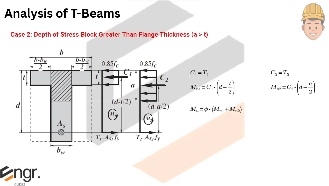
Because the compression block extends into the web, use the flange-plus-web compression equation: