CECC-483 Reference Formula Sheet — Working Stress Design
Quick-reference WSD/ADM permissible stresses, transformed-section properties, and resisting-moment formulas as listed in the CECC-483 / NSCP review notes.
Working Stress Design Method (Alternate Design Method)
The Working Stress Design (WSD) method — also called the Alternate Design Method (ADM) — designs reinforced-concrete sections so that, under service (un-factored) loads, the maximum bending stresses in concrete and steel never exceed their allowable values. Both materials are assumed to behave elastically, plane sections remain plane, and the tensile strength of concrete is neglected.
Internal forces in a singly-reinforced beam (cracked section):
With $kd$ measured from the extreme compression fibre to the neutral axis (N.A.) and $jd=d-\dfrac{kd}{3}$ the lever arm between the resultant compressive force $C$ and the steel tensile force $T$:
Minimum clear spacing between parallel bars in a layer: $d_b$ but not less than $25$ mm.
Minimum clear vertical spacing between layers of bars: $25$ mm.
Minimum concrete cover (not exposed to weather or earth): $40$ mm. Exposed: $50$ mm for No. 19 to No. 57 bars, $40$ mm for No. 16 and smaller.
Economical proportions (when not architecturally restricted): $\dfrac{2}{3}\gt\dfrac{b}{d}\gt\dfrac{1}{2}\;\;\text{or}\;\;\dfrac{3}{2}b\lt d\lt 2b$.
Doubly-reinforced beams. When the section is dimensionally restricted and $M_{ext}\gt M_{int}$ for a singly-reinforced solution, add compression steel $A'_s$ at depth $d'$ from the top fibre. The external moment is split into two couples:
Calculate the maximum flexural stresses in concrete and steel for a rectangular reinforced-concrete beam with width $b=300$ mm, effective depth $d=420$ mm, total depth $h=500$ mm, and tension reinforcement $A_s=3\,\phi 28=1847\text{ mm}^2$ placed in a single bottom row. The applied service moment is $M=95\text{ kN}\!\cdot\!\text{m}$ and the modular ratio is $n=9$.
Step 1 — Steel ratio and $n\rho$. Because this is an analysis problem (As is known), use $k=\sqrt{(n\rho)^2+2n\rho}-n\rho$:
Design the simply-supported beam of span $L=6\text{ m}$ to carry a service dead load of $35\text{ kN/m}$ and service live load of $15\text{ kN/m}$. Use $f'_c=21\text{ MPa}$, $f_y=300\text{ MPa}$, and $\phi 28$ mm main bars with $\phi 12$ mm stirrups and $40$ mm clear cover.
Step 1 — Service moment. Total service load $w=35+15=50\text{ kN/m}$. For a simply supported beam:
Revised effective depth (accounting for two layers with $25$ mm clear vertical spacing):
$$d=710-40-12-28+\tfrac{25}{2}=618\text{ mm}$$
Final design: $b=350$ mm, $h=710$ mm, $d=618$ mm, tension reinforcement $5\,\phi 28$ in two layers (3 below + 2 above).
Problem: Doubly-Reinforced Beam — Analysis
A doubly-reinforced rectangular beam has $b=320$ mm, $d=400$ mm, $d'=70$ mm, tension steel $A_s=4\,\phi 28=2464\text{ mm}^2$ and compression steel $A'_s=2\,\phi 25=982\text{ mm}^2$. Using $f'_c=21$ MPa, $f_y=300$ MPa and $n=9$, determine the allowable service moment of the section.
Step 2 — Locate the neutral axis from the first moment of the transformed cracked section about the N.A. Compression steel is transformed with $(2n-1)$:
Find the required tension and compression reinforcement of a rectangular beam with $b=320$ mm, $d=400$ mm, $d'=70$ mm subjected to a positive service moment $M=120\text{ kN}\!\cdot\!\text{m}$. Use $f'_c=21\text{ MPa}$ and $f_y=300\text{ MPa}$.
Step 1 — Allowable stresses and elastic constants.
Step 3 — Singly-balanced moment $M_1$. This is the maximum moment that the singly section ($A_{s1}=\rho_e bd$) can carry while keeping both stresses at their allowable values:
A beam has a width of 300mm and a total depth of 550mm. The beam has a length of 8m and is fixed at both ends. It is reinforced with 3-28mm⌀ bars at the tension side and 2-25mm⌀ bars at the compression side. Using a steel cover of 70mm, fc'=21MPa, fy=276MPa. Use 24kN/m3 as unit weight of concrete. Superimposed Dead Load = 8kN/m Live Load = 12 kN/m Using alternate design method.
Determine the transformed moment of inertia with respect to the neutral axis in mm4
2247.21x106
2274.21x106
2742.21x106
2217.41x106
Determine the actual stress of concrete at the midspan in MPa.
4.54
6.78
3.46
8.48
Determine the actual stress of tension steel at the midspan in MPa.
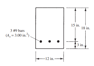
Compute the bending stresses in the extreme fibers for a bending moment of 25 k-ft. The normal-weight concrete has an f'c = 4000 psi and a modulus of rupture fr = 7.5(1)√4000 psi = 474 psi.
462.963 psi
426.396 psi
294.640 psi
249.460 psi
Determine the cracking moment of the section.
25.614 k-ft
25.146 k-ft
49.420 k-ft
49.240 k-ft
Part 1.
For the uncracked rectangular section, use the gross moment of inertia: $I_g=\frac{bh^3}{12}=\frac{12(18^3)}{12}=5832\text{ in}^4$ The extreme-fiber distance is $c=18/2=9$ in. Convert the moment: $M=25\text{ k-ft}=300\text{ kip-in}$ $f=\frac{Mc}{I}=\frac{300(9)}{5832}=0.462963\text{ ksi}$ $\boxed{f=462.963\text{ psi}}$
Part 2.
Cracking occurs when the extreme-fiber stress reaches the modulus of rupture $f_r=474$ psi. $M_{cr}=\frac{f_r I_g}{c}$ $M_{cr}=\frac{474(5832)}{9}=307{,}136\text{ lb-in}$ $M_{cr}=\frac{307{,}136}{12{,}000}=25.594\text{ k-ft}$ $\boxed{M_{cr}\approx25.614\text{ k-ft}}$