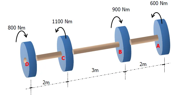
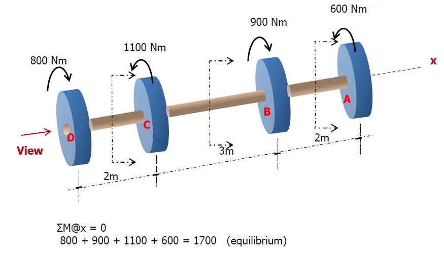
An aluminum shaft with a constant diameter of 50mm is loaded by torques applied to gears to it as shown. Using G=28GPa, determine the relative angle of twist in degrees of gear D relative to gear A.
See images:
$$\theta_{A/D}= \theta_{AB}+\theta_{BC}+\theta_{CD}$$
Since the shaft has the same diameter and material throughout, the polar moment of inertia $J$ and the shear modulus $G$ are constant.
Thus, $J$ and $G$, as well as the conversion factor for moment to transform it into $N\cdot mm$, may be factored out of the summation when computing the total angle of twist.
$$
\frac{\theta}{A}
=
\frac{1000^2}{\left(\frac{\pi}{32}(50^4)\right)(28(1000))}
\left[
800(2) - 300(3) + 600(2)
\right]
\left(\frac{180^\circ}{\pi \text{ rad}}\right)
$$
$$
\theta_{A/D} = 6.34^\circ \text{(counterclockwise relative to gear A)}
$$
Torque Diagram
To construct the torque diagram, we move from the left end of the shaft toward the right and keep track of the algebraic sum of torques acting on the shaft.
A positive torque causes the diagram to step upward, while a negative torque causes it to step downward.
Step-by-Step Construction
-
At point D, an applied torque of $800\ \text{Nm}$ acts on the shaft.
-
Between D and C (length $2\ \text{m}$), the internal torque remains constant:
$$
T = +800\ \text{Nm}
$$
-
At point C, a torque of $1100\ \text{Nm}$ is applied in the opposite sense.
The new internal torque becomes
$$
T = 800 - 1100 = -300\ \text{Nm}
$$
-
Between C and B (length $3\ \text{m}$), the torque diagram stays constant at
$$
T = -300\ \text{Nm}
$$
-
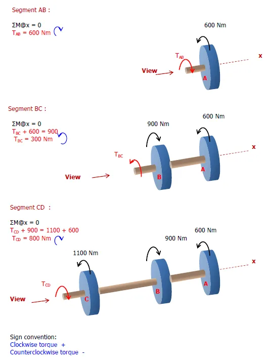
At point B, a torque of $900\ \text{Nm}$ acts in the positive direction:
$$
T = -300 + 900 = 600\ \text{Nm}
$$
-
Between B and A (length $2\ \text{m}$), the torque remains constant:
$$
T = 600\ \text{Nm}
$$
-
At point A, the applied torque of $600\ \text{Nm}$ brings the diagram back to zero:
$$
600 - 600 = 0
$$
Torque Diagram