CE Board Exam Randomizer

⬅ Back to Subject Topics

Moving Loads

Derivation of Conventional Method by Calculus (Maxima-Minima)

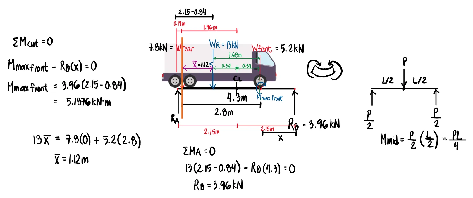
Since the value of x describes the distance at which the load must be placed from the left end, $x=\frac{L-\bar{x}}{2}$ can be expanded into $L/2-\bar{x}/2$. This means that we must place the load of interest at the midspan but move it slightly to the left by a distance $\bar{x}/2$ or halfway between the load of interest and the centroid of the loads.

Illustration of how the Shear and Moment Diagram is Affected upon the Movement of Loads

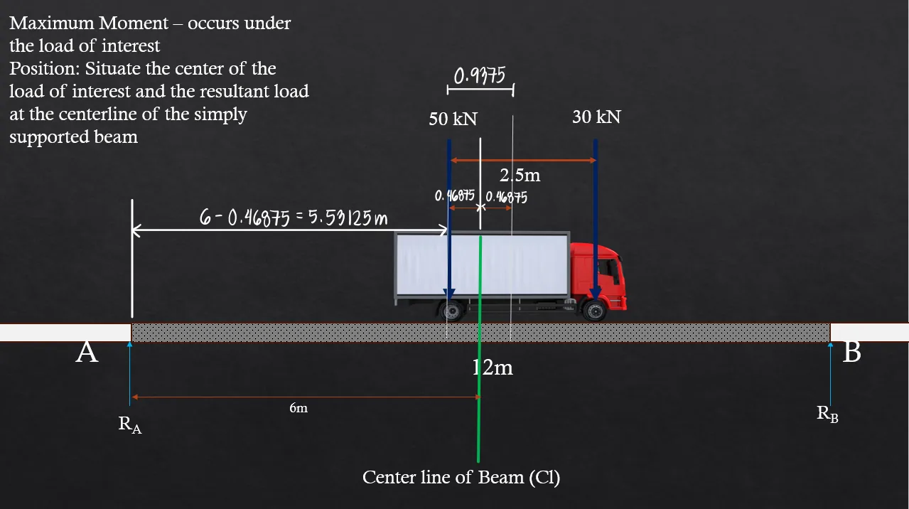
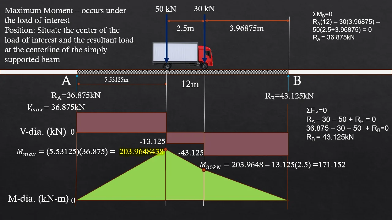
Observe here that there is a specific placement of the loads that produces the maximum possible moment that the beam can experience. It occurs when the 50kN load is at a distance 5.53125 meters from the left. Notice that if we move it slightly to the right from that position, such as in the last image, where the 50kN load is placed 6 meters from the left, the maximum moment under the load would be 202.5kN-m, slightly lesser than 203.96kN-m.

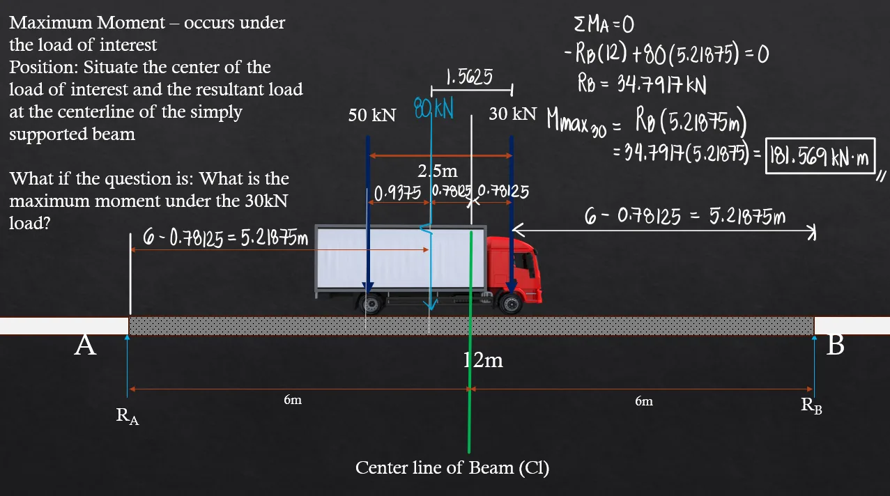
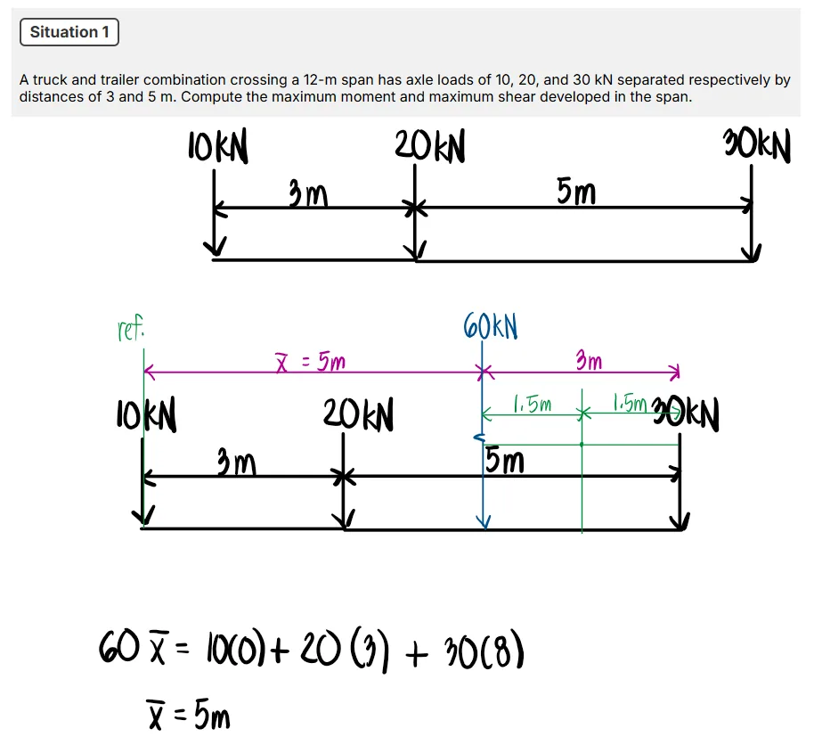
The question now would be: How do we identify the optimal placement of the loads that would produce the largest possible moment along the beam? We will cover the two methods of solving (Maxima-minima and Classical Method) as well as Calculator Techniques in the problems below.

Problem 1: (Two Moving Loads with Shorcut Formula)

A truck with axle loads of 50kN and 30kN on a wheel base of 2.5m crosses a 10-m span. Compute the maximum shearing force and the maximum bending moment.

Diagram Diagram Diagram

First, we compute the resultant load of the parallel force system as well as its location from our reference axis at the 50kN load. One may choose any reference axis, depending on preference.

Solution Solution

The maximum bending moment for two moving loads, given that all loads are inside the span, occurs under the larger load. Here, we draw the entire shear and moment diagram for the purpose of demonstration. The computed maximum bending moment is 203.96kN-m. Alternatively, we can use the general formula for the maximum moment caused by two moving loads (if all loads are within the span): $$\frac{(PL-P_s(d))^2}{4PL}$$where:
$P=P_{bigger}+P_{smaller}$
$P_s=smaller \ load$
$L=length \ of \ span$
$d=distance \ between\ wheel \ loads$
Therefore, we have:
$$\frac{(80 \cdot 12-30 \cdot 2.5)^2}{4 \cdot 80 \cdot 12} = \boxed{203.96kN \cdot m}$$

Solution Solution Solution

Problem 2: (Two Moving Loads with One Load Outside the Span + General Formula for One Moving Load)

A truck weighing 13kN has a wheel base of 2.8m. It carries 60% of its load on the rear side. Compute the maximum moment and maximum shear if it crosses a 4.3m span.

Diagram Diagram Diagram

The resultant load here is the total load of 13kN. The rear load is 60% of 13kN, which is 7.8kN, and the front load is, therefore, 5.2kN. Computing the location of the resultant with the reference axis at the rear load:

Solution

Using the concept of the placement of the loads where we take the center point of the load of interest and the resultant, and place it at the midspan, we would develop the figure below. However, it is important to notice that the front load would be outside the span. We verify this by solving the corresponding distances. Since 2.24m > 2.15m, the front load will be outside the span, and so our computation of the maximum moment will discount the front load.

Solution

The proper configuration for the maximum moment under the 7.8kN load, therefore, is one where the truck moves slightly to the right so that the 7.8kN load is directly over the midspan. Here, we can apply the general formula for the maximum moment caused by a concentrated load at the midspan for simply supported beams, PL/4. This value is the maximum moment under the 7.8kN load.

Solution

Now that we have finished computing the maximum moment under the rear load, we are also interested in computing the maximum moment under the front load. We do this by getting the center point between the resultant 13kN load and the front load, and placing that center point on the midspan of the beam. Then, we cut the beam exactly at the front load and take moments from the right to simplify the calculation. We could obtain the same result by taking moments from the left, but more loads would have to be considered.

Solution

To compute the maximum shear, we simply place the extreme load closest to the resultant over the support. The resultant is closer to the rear load, so we place the rear load at point A. If, for instance, the resultant is closer to the front load, then we solve the maximum shear by placing the front load at the right support (B). The support reaction directly below the extreme load will be the maximum shear in the beam, as we place it at a differential distance x from the support.

Solution

Problem 3:

Refer to the image shown:

Diagram Diagram Diagram

See images:

Solution Solution Solution Solution

Problem 4: (Three Moving Loads with a Load Outside the Span)

A truck and trailer combination crossing a 12-m span has axle loads of 10, 20, and 30kN separated respectively by distances of 3 and 5m. Compute the maximum moment and maximum shear developed in the span.

Diagram Diagram Diagram

See images:

Solution Solution Solution Solution Solution

Problem 5:

Refer to the image shown:

Diagram Diagram Diagram

See images:

Solution Solution Solution Solution

Problem 6:

Refer to the image shown:

Diagram Diagram Diagram

See images:

Solution Solution Solution Solution

Problem 7:

Refer to the image shown:

Diagram Diagram Diagram

See images:

Solution Solution Solution Solution

Problem 8:

Refer to the image shown:

Diagram Diagram Diagram

See images:

Solution Solution Solution Solution
-->
Scroll to zoom