CE Board Exam Randomizer

⬅ Back to Subject Topics

Flanged Bolt Couplings

Concept Concept Concept Concept Concept Concept Concept Concept Concept

General Relationship (Concentric Bolt Circles with Varying Materials)

$$\frac{T_1\cdot G_1}{R_1} \;=\; \frac{T_2\cdot G_2}{R_2}$$

Polar Moment of Inertia of Bolt Group

The polar moment of inertia of a bolt group about its centroid is obtained by summing the area of each bolt multiplied by the square of its radial distance from the centroid.

Starting from the definition of polar moment of inertia:

$$ J = \sum A_n r_n^2 $$

where $ r_n $ is the radial distance of the n-th bolt from the centroid of the bolt group. The radial distance can be expressed in terms of the rectangular coordinates:

$$ r_n^2 = x_n^2 + y_n^2 $$

Substituting this relationship into the polar moment expression:

$$ J = \sum A_n (x_n^2 + y_n^2) $$

If all bolts have the same area $A$, the area can be factored out of the summation.

$$ J = A \sum (x_n^2 + y_n^2) $$

This is the commonly used expression for the polar moment of inertia of a bolt group.

The radial distance $r$ is sometimes denoted by the Greek letter $\rho$, so the definition may also appear as:

$$ J = \sum A \rho^2 $$

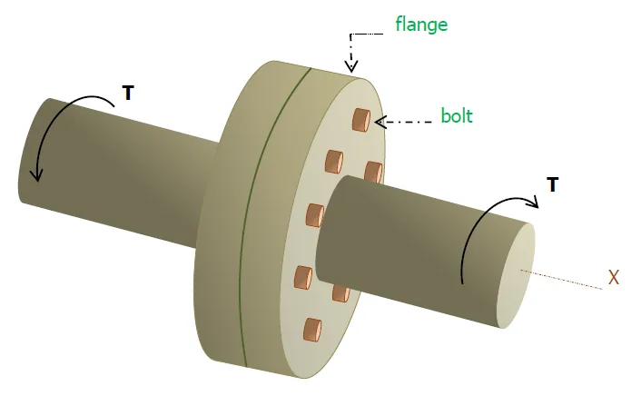
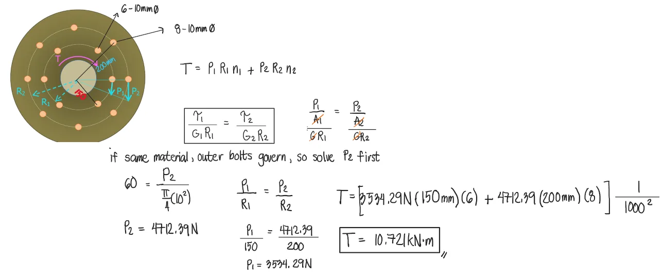
Problem 1: Flanged Bolt Coupling | Uniform Material

A flanged bolt coupling consists of eight 10mm diameter steel bolts on a bolt circle 400mm in diameter, and six 10mm diameter steel bolts on a concentric bolt circle 300mm in diameter. What torque (kN-m) can be applied without exceeding a shearing stress of 60MPa in the bolts?

Flanged Bolt Couplings | Mechanics of Deformable Bodies – Problem 1: – Diagram Flanged Bolt Couplings | Mechanics of Deformable Bodies – Problem 1: – Diagram Flanged Bolt Couplings | Mechanics of Deformable Bodies – Problem 1: – Diagram

See images:

Flanged Bolt Couplings | Mechanics of Deformable Bodies – Problem 1: – Diagram Flanged Bolt Couplings | Mechanics of Deformable Bodies – Problem 1: – Diagram Flanged Bolt Couplings | Mechanics of Deformable Bodies – Problem 1: – Diagram Flanged Bolt Couplings | Mechanics of Deformable Bodies – Problem 1: – Diagram

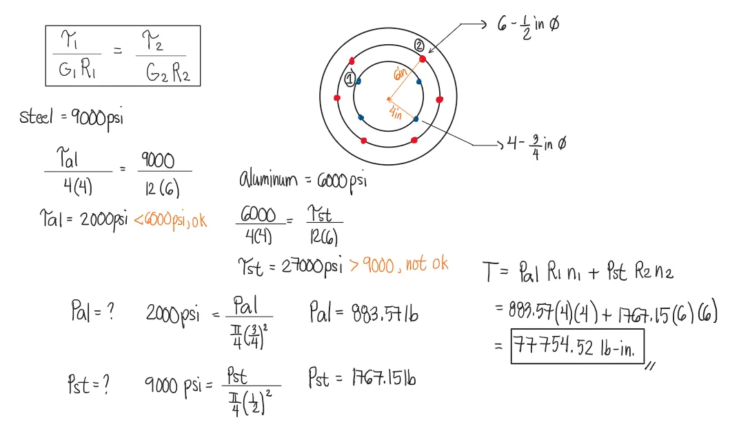
Problem 2: Flanged Bolt Coupling | Varying Material

A flanged bolt coupling consists of six 1/2 in. steel bolts evenly spaced around a bolt circle 12 in. in diameter, and four 3/4 in. aluminum bolts on a concentric bolt circle 8in. in diameter. What torque can be applied without exceeding 9000psi in the steel or 6000psi in the aluminum?
Material Properties:
$G_{st}=12x10^6psi$
$G_{al}=4x10^6psi$

Flanged Bolt Couplings | Mechanics of Deformable Bodies – Problem 2: – Diagram Flanged Bolt Couplings | Mechanics of Deformable Bodies – Problem 2: – Diagram Flanged Bolt Couplings | Mechanics of Deformable Bodies – Problem 2: – Diagram

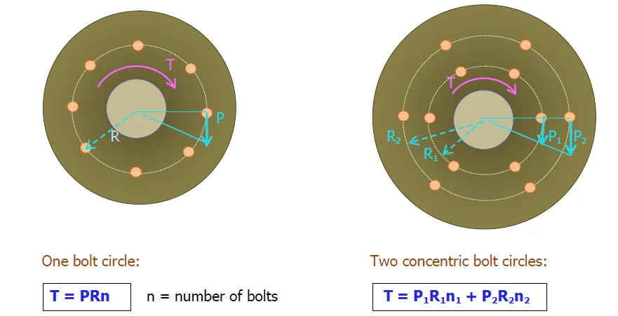
In this problem, we first check which of the stresses will govern since we have varying limits of stress for steel and aluminum. We use the general relationship (Concentric Bolt Circles with Varying Materials)

Flanged Bolt Couplings | Mechanics of Deformable Bodies – Problem 2: – Diagram Flanged Bolt Couplings | Mechanics of Deformable Bodies – Problem 2: – Diagram Flanged Bolt Couplings | Mechanics of Deformable Bodies – Problem 2: – Diagram Flanged Bolt Couplings | Mechanics of Deformable Bodies – Problem 2: – Diagram

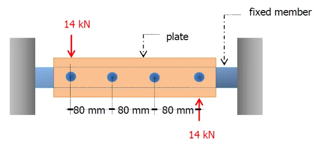
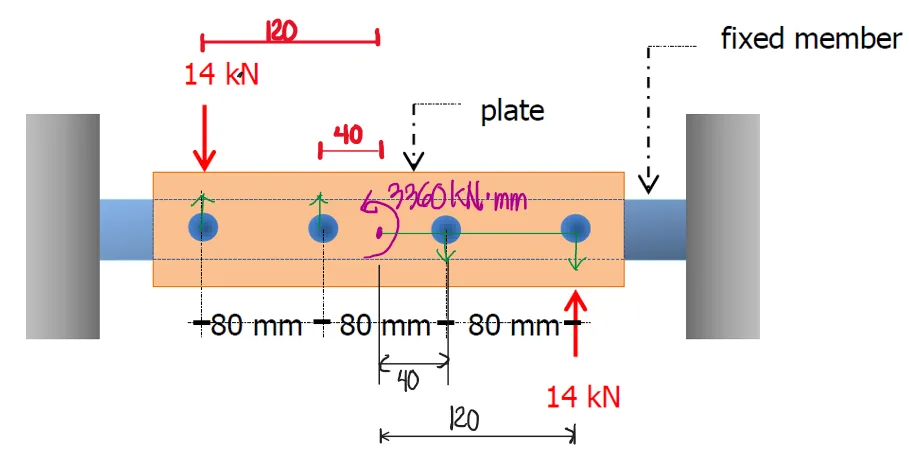
Problem 3: Couple Applied on a Horizontal Bolt Group

A plate is fastened to a fixed member by four 20mm diameter rivets arranged as shown. Compute the maximum and minimum shearing stress (MPa) developed in the rivets.

Flanged Bolt Couplings | Mechanics of Deformable Bodies – Problem 3: – Diagram Flanged Bolt Couplings | Mechanics of Deformable Bodies – Problem 3: – Diagram Flanged Bolt Couplings | Mechanics of Deformable Bodies – Problem 3: – Diagram

FBD:

Flanged Bolt Couplings | Mechanics of Deformable Bodies – Problem 3: – Diagram

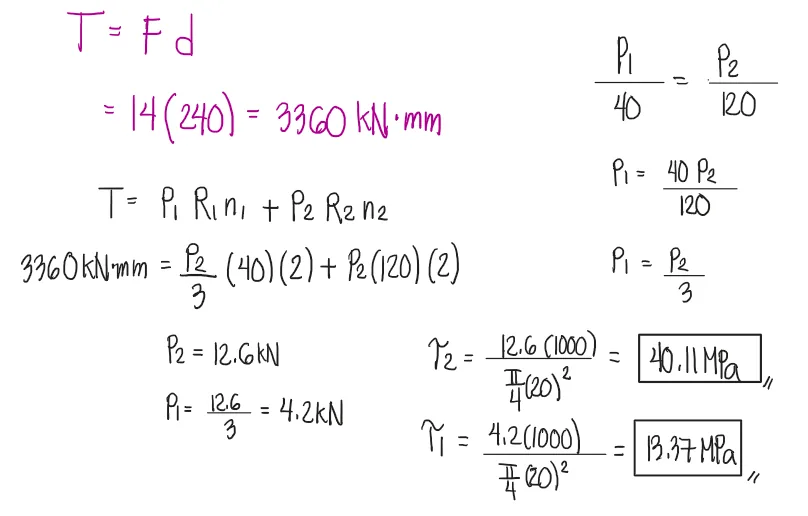
We first solve the problem conventionally:

Flanged Bolt Couplings | Mechanics of Deformable Bodies – Problem 3: – Diagram

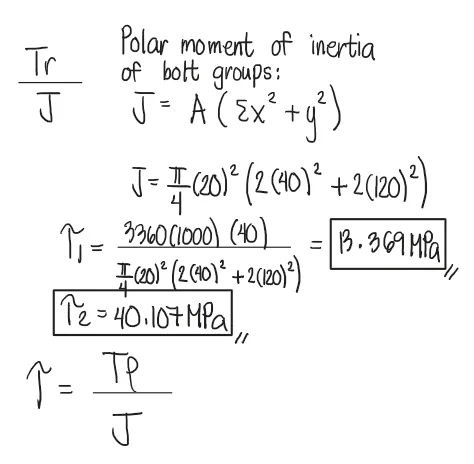
Alternatively, we may use the formula for torsional shear stress: $$\tau=\frac{T\cdot r}{J}$$
where J is the polar moment of inertia of the BOLT GROUP. We obtain it using: $$J=A\cdot (\Sigma x^2 + \Sigma y^2)$$
where A = Area of one bolt/rivet (if area is uniform)

Notice that we are able to obtain the same shear stresses, 13.369MPa and 40.107MPa, below. Note, however, that this works only if the rivet/bolt-material is uniform. If the materials have varying working or allowable shear stresses, then it is more advantageous to use the conventional method in problem 2.

Flanged Bolt Couplings | Mechanics of Deformable Bodies – Problem 3: – Diagram Flanged Bolt Couplings | Mechanics of Deformable Bodies – Problem 3: – Diagram

Problem 4:

Refer to the image shown:

Flanged Bolt Couplings | Mechanics of Deformable Bodies – Problem 4: – Diagram Flanged Bolt Couplings | Mechanics of Deformable Bodies – Problem 4: – Diagram Flanged Bolt Couplings | Mechanics of Deformable Bodies – Problem 4: – Diagram

See images:

Flanged Bolt Couplings | Mechanics of Deformable Bodies – Problem 4: – Diagram Flanged Bolt Couplings | Mechanics of Deformable Bodies – Problem 4: – Diagram Flanged Bolt Couplings | Mechanics of Deformable Bodies – Problem 4: – Diagram Flanged Bolt Couplings | Mechanics of Deformable Bodies – Problem 4: – Diagram

Problem 5:

Refer to the image shown:

Flanged Bolt Couplings | Mechanics of Deformable Bodies – Problem 5: – Diagram Flanged Bolt Couplings | Mechanics of Deformable Bodies – Problem 5: – Diagram Flanged Bolt Couplings | Mechanics of Deformable Bodies – Problem 5: – Diagram

See images:

Flanged Bolt Couplings | Mechanics of Deformable Bodies – Problem 5: – Diagram Flanged Bolt Couplings | Mechanics of Deformable Bodies – Problem 5: – Diagram Flanged Bolt Couplings | Mechanics of Deformable Bodies – Problem 5: – Diagram Flanged Bolt Couplings | Mechanics of Deformable Bodies – Problem 5: – Diagram

Problem 6:

Refer to the image shown:

Flanged Bolt Couplings | Mechanics of Deformable Bodies – Problem 6: – Diagram Flanged Bolt Couplings | Mechanics of Deformable Bodies – Problem 6: – Diagram Flanged Bolt Couplings | Mechanics of Deformable Bodies – Problem 6: – Diagram

See images:

Flanged Bolt Couplings | Mechanics of Deformable Bodies – Problem 6: – Diagram Flanged Bolt Couplings | Mechanics of Deformable Bodies – Problem 6: – Diagram Flanged Bolt Couplings | Mechanics of Deformable Bodies – Problem 6: – Diagram Flanged Bolt Couplings | Mechanics of Deformable Bodies – Problem 6: – Diagram

Problem 7:

Refer to the image shown:

Flanged Bolt Couplings | Mechanics of Deformable Bodies – Problem 7: – Diagram Flanged Bolt Couplings | Mechanics of Deformable Bodies – Problem 7: – Diagram Flanged Bolt Couplings | Mechanics of Deformable Bodies – Problem 7: – Diagram

See images:

Flanged Bolt Couplings | Mechanics of Deformable Bodies – Problem 7: – Diagram Flanged Bolt Couplings | Mechanics of Deformable Bodies – Problem 7: – Diagram Flanged Bolt Couplings | Mechanics of Deformable Bodies – Problem 7: – Diagram Flanged Bolt Couplings | Mechanics of Deformable Bodies – Problem 7: – Diagram

Problem 8:

Refer to the image shown:

Flanged Bolt Couplings | Mechanics of Deformable Bodies – Problem 8: – Diagram Flanged Bolt Couplings | Mechanics of Deformable Bodies – Problem 8: – Diagram Flanged Bolt Couplings | Mechanics of Deformable Bodies – Problem 8: – Diagram

See images:

Flanged Bolt Couplings | Mechanics of Deformable Bodies – Problem 8: – Diagram Flanged Bolt Couplings | Mechanics of Deformable Bodies – Problem 8: – Diagram Flanged Bolt Couplings | Mechanics of Deformable Bodies – Problem 8: – Diagram Flanged Bolt Couplings | Mechanics of Deformable Bodies – Problem 8: – Diagram
Scroll to zoom