Shafts are often used to deliver mechanical power. If a shaft carries a torque $T$ while rotating with angular
speed $\omega$, the transmitted power is given by $P = T\omega$. Since the angular speed can also be written as
$\omega = 2\pi f$, where $f$ is the rotational frequency, the torque may be rewritten as:
$$T=\frac{P}{2\pi f}$$
In SI, power $P$ is commonly expressed in watts $(1.0\ \text{W} = 1.0\ \text{N}\cdot\text{m/s})$ while frequency
$f$ is given in hertz $(1.0\ \text{Hz} = 1.0\ \text{rev/s})$, so the formula yields torque in $\text{N}\cdot\text{m}$.
In U.S. customary units, if $P$ is stated in $\text{lb}\cdot\text{in./s}$ and $f$ in hertz, the same relation gives
torque in $\text{lb}\cdot\text{in.}$ Because power is frequently reported in horsepower
$(1.0\ \text{hp} = 550\ \text{lb}\cdot\text{ft/s} = 396 \times 10^3\ \text{lb}\cdot\text{in./min})$, an equivalent
and more convenient form of the equation is also often used.
Statically Indeterminate Torsion Problems
The solution process for statically indeterminate torsion cases is much like the method used for indeterminate
axially loaded members:
Sketch the needed free-body diagrams and write the equilibrium equations.
Set up compatibility equations based on the restrictions on angle of twist.
Use the torque-twist relationships to rewrite the compatibility equations in terms of torque.
Solve the equilibrium and compatibility equations to obtain the unknown torques.
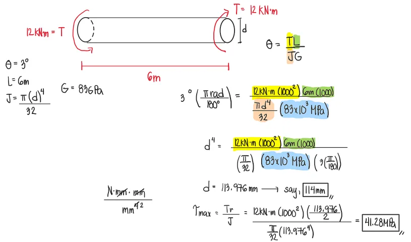
What is the minimum diameter (mm) of a solid steel shaft that will not twist through more than 3˚ in a 6m length when subjected to a torque of 12 kNm? What maximum shearing stress (MPa) is developed? Use G = 83 GPa.
See images:
Problem: Relative Angle of Twist | Multiple Torques Applied
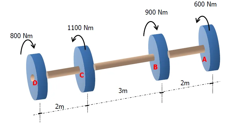
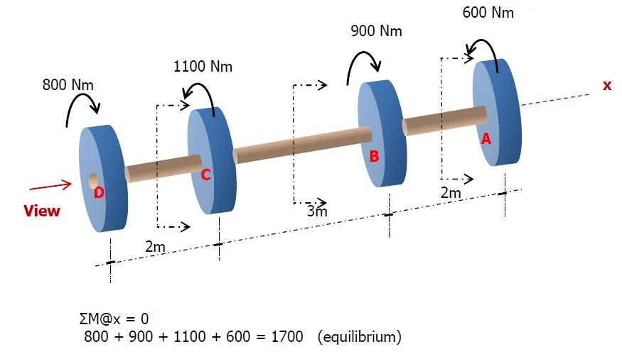
An aluminum shaft with a constant diameter of 50mm is loaded by torques applied to gears to it as shown. Using G=28GPa, determine the relative angle of twist in degrees of gear D relative to gear A.
Since the shaft has the same diameter and material throughout, the polar moment of inertia $J$ and the shear modulus $G$ are constant.
Thus, $J$ and $G$, as well as the conversion factor for moment to transform it into $N\cdot mm$, may be factored out of the summation when computing the total angle of twist.
$$
\theta_{A/D} = 6.34^\circ \text{(counterclockwise relative to gear A)}
$$
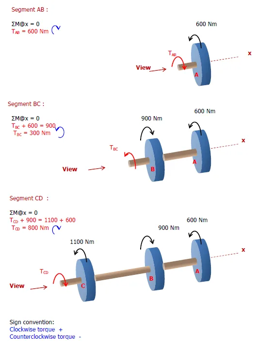
Torque Diagram
To construct the torque diagram, we move from the left end of the shaft toward the right and keep track of the algebraic sum of torques acting on the shaft.
A positive torque causes the diagram to step upward, while a negative torque causes it to step downward.
Step-by-Step Construction
At point D, an applied torque of $800\ \text{Nm}$ acts on the shaft.
Between D and C (length $2\ \text{m}$), the internal torque remains constant:
$$
T = +800\ \text{Nm}
$$
At point C, a torque of $1100\ \text{Nm}$ is applied in the opposite sense.
The new internal torque becomes
$$
T = 800 - 1100 = -300\ \text{Nm}
$$
Between C and B (length $3\ \text{m}$), the torque diagram stays constant at
$$
T = -300\ \text{Nm}
$$
At point B, a torque of $900\ \text{Nm}$ acts in the positive direction:
$$
T = -300 + 900 = 600\ \text{Nm}
$$
Between B and A (length $2\ \text{m}$), the torque remains constant:
$$
T = 600\ \text{Nm}
$$
At point A, the applied torque of $600\ \text{Nm}$ brings the diagram back to zero:
$$
600 - 600 = 0
$$
Torque Diagram
Problem: Minimum Diameter given the Power and Frequency
A solid steel shaft in a rolling mill transmits 20kW of power at 2Hz. Determine the smallest safe diameter of the shaft if the shear stress is not to exceed 40MPa and the angle of twist is limited to 6º in a length of 3m. Use G=83GPa.
See images:
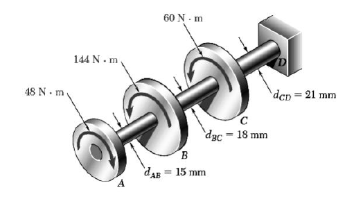
Problem: Statically Indeterminate Member | Compound Shaft in Torsion
The compound shaft composed of steel, aluminum, and bronze segments, carries the two torques as shown. If TC=250lb-ft, determine the maximum shear stress developed in each material. The moduli of rigidity for steel, aluminum, and bronze are 12x106psi, 4x10⁶psi, and 6x10⁶psi, respectively.
See images:
Problem:
Refer to the image shown:
See images:
Problem:
Refer to the image shown:
See images:
Problem:
Refer to the image shown:
See images:
Problem:
Refer to the image shown:
See images:
🧭 Jump to:
Scroll to zoom
Exam Generator Problems
Additional board-style practice items for this topic.
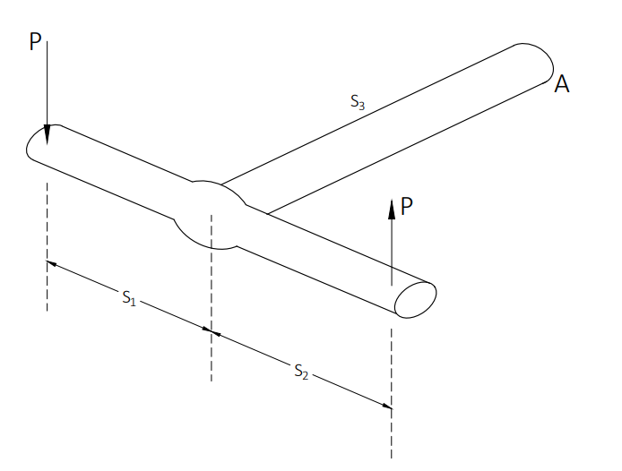
A torque wrench is used to tighten the pipe shown. Given: S1 = 400mm S2 = 250mm S3 = 100mm Modulus of Rigidity G = 78MPa Allowable shear stress = 60MPa
The diameter of the solid pipe is 20mm. How much is the maximum force P (N) that can be applied based on the allowable shear stress?
145
160
120
100
For a hollow pipe with 50mm outside diameter and a thickness of 6mm, compute the maximum force P (kN) that can be applied such that the angle of twist at A does not exceed 5º.
42.80
28.80
32.70
51.40
The torque applied to tighten the hollow pipe is 200N-m. If the outside diameter of the pipe is 50mm and the pipe thickness is 6mm, determine the maximum shear stress (MPa) in the pipe.
An aluminum bar of solid circular cross-section is twisted by torques T acting at the ends. The dimensions and shear modulu of elasticity are as follows: L = 1.4m, d = 35mm, and G = 28GPa
Determine the torsional stiffness of the bar.
2950N-m
1810N-m
2059N-m
1905N-m
If the angle of twist of the bar is 7º, what is the maximum shear stress?
43MPa
48MPa
36MPa
28MPa
If the angle of twist of the bar is 5º, what is the maximum shear strain (in radians)?
Two shafts A and B transmit the same power. The speed of shaft A is 250
rpm and that of shaft B is 300 rpm. Which of the following is true?
Answer:
shaft A has greater diameter
shaft B has greater diameter
both shafts have equal torque
shafts have equal shearing stress
Solution pending in psadquestions/q560.json.
Question Bank: q598
PSAD - Mechanics of Deformable Bodies / Torsion / Mastermatician
Refer to the figure shown:
The shaft in which the maximum shearing stress occurs is at:
CD
DE
AB
BC
The magnitude of the maximum shearing stress (in MPa).
85.8
58.8
85.5
88.8
Solution pending in psadquestions/q598.json.
Question Bank: q747
PSAD - Mechanics of Deformable Bodies / Torsion / Mastermatician
Find the minimum outer diameter of a hollow shaft that will not twist by more than 5º when subjected to a stress of 50MPa on a length of 2m. Use G=83GPa.
28mm
25mm
24mm
20mm
Solution pending in psadquestions/q747.json.
Question Bank: q748
PSAD - Mechanics of Deformable Bodies / Torsion / Mastermatician
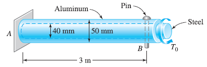
The steel rod fits loosely inside the aluminum sleeve. Both components are attached to a rigid wall at A and jointed together by a pin at B. Because of a slight misalignment of the pre-drilled holes, the torque T0=750N-m was applied to the steel rod before the pin could be inserted into the holes. Determine the torque in each component after T0 was removed. Use G=80GPa for steel and G=28GPa for aluminum.
251N-m
260N-m
274N-m
246N-m
Solution pending in psadquestions/q748.json.
Question Bank: q749
PSAD - Mechanics of Deformable Bodies / Torsion / Mastermatician
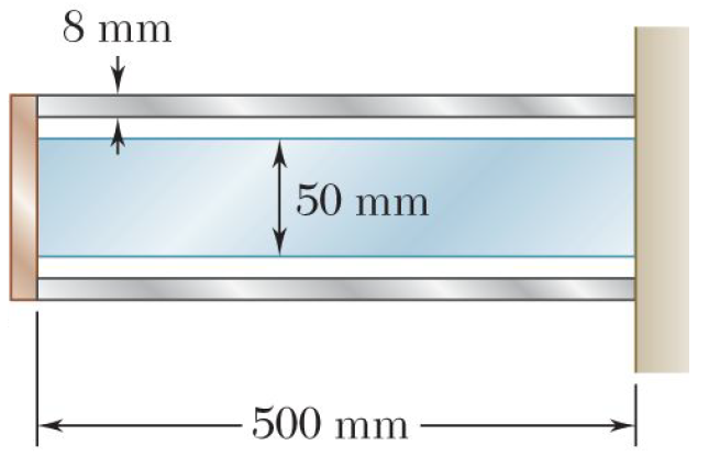
A steel shaft and an aluminum tube are connected to a fixed wall and to a rigid disk as shown. Knowing that the initial stresses are zero, determine the maximum torque T that can be applied to the disk if the allowable stresses are 120MPa in the steel shaft and 70MPa in the aluminum tube. Use G=77GPa for steel and G=27GPa for aluminum.
Formula-mode item rendered with fixed values for lecture/PDF export.
A hollow steel shaft shall not twist by more than 5.6º in a length of 8m when subjected to a torque of 14.5kN-m. The steel shaft is made of steel which has a modulus of rigidity of 83GPa. The outer diameter of the shaft is 300mm.
Determine the minimum inner diameter of the shaft (in mm).
298.64218558192886
296.64218558192886
294.64218558192886
292.64218558192886
Determine the maximum shearing stress (in MPa) developed in the shaft.
Formula-mode item rendered with fixed values for lecture/PDF export.
A flanged bolt coupling consists of 12 - 20mm∅ steel bolts evenly spaced around a bolt circle 340 mm in diameter and 6 - 12mm∅ aluminum bolts on a concentric bolt circle 240mm in diameter. Gst=83GPa and Gal=28GPa. The allowable stresses are as follows:
σst=250MPa
σal=34MPa
Determine the maximum force that can be carried by the aluminum bolts.
3845.309407993907
6732.938472328515
10681.415022205298
18702.60686757921
Determine the maximum force that can be carried by the steel bolts.