Conjugate Beam Method
The Conjugate Beam Method is a powerful technique used to determine the slope and deflection in a real beam by analyzing a related, imaginary beam called the conjugate beam.
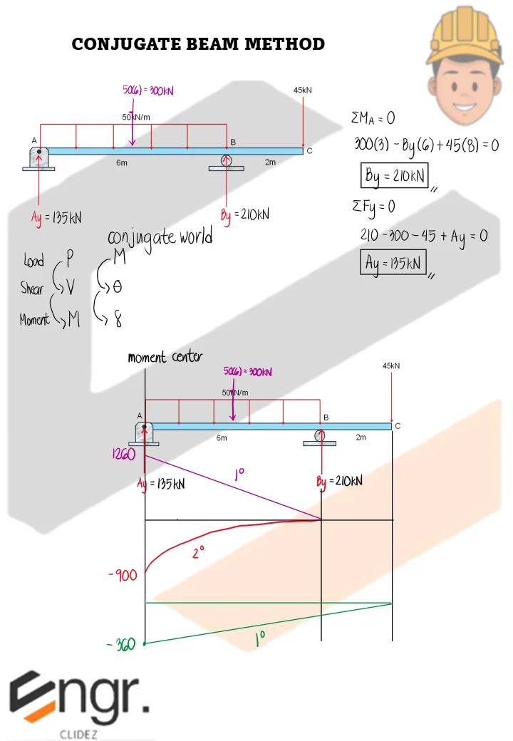
To understand this method, we compare two sets of relationships:
- Group A (Statics): Load → Shear → Moment
- Group B (Deformation): Moment → Slope → Deflection
From the double integration method, we recall the following relationships:
Moment-curvature relation:
Slope equation:
Deflection equation:
These equations show that moment, slope, and deflection follow a pattern similar to load, shear, and moment in statics. Hence, we establish the following analogy:
Theorems of the Conjugate Beam Method:
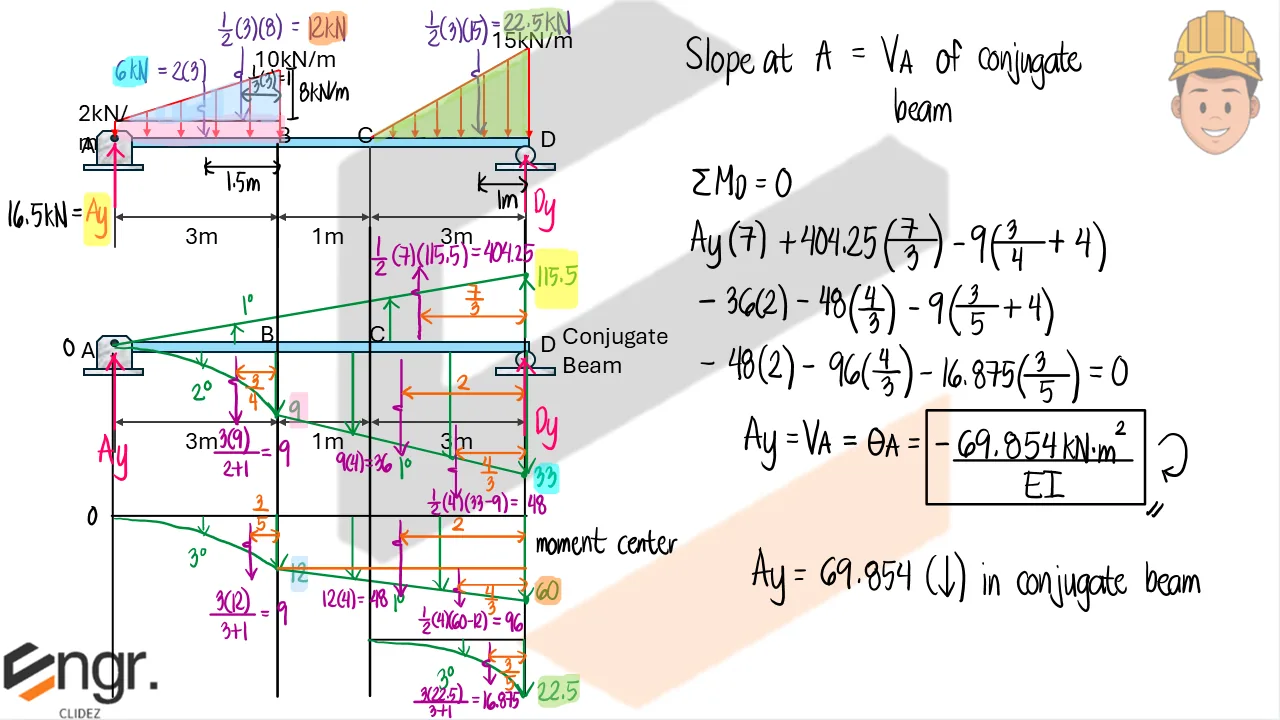
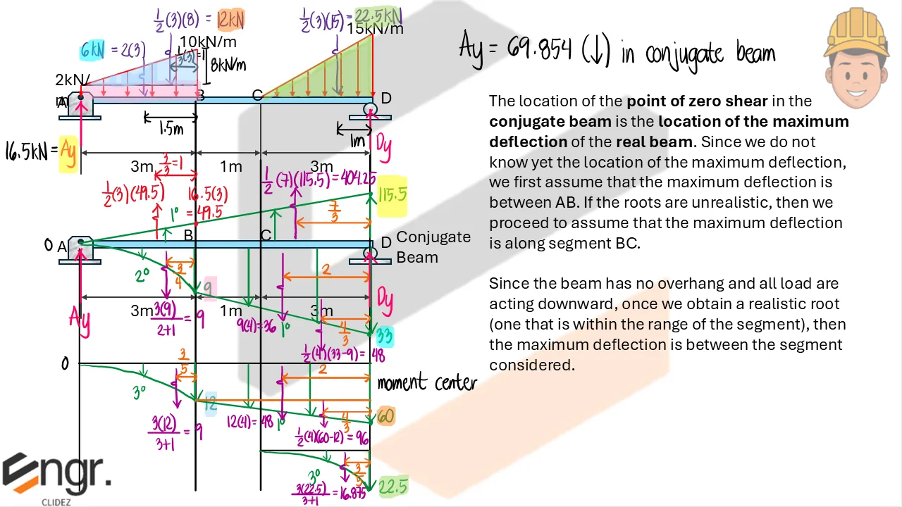
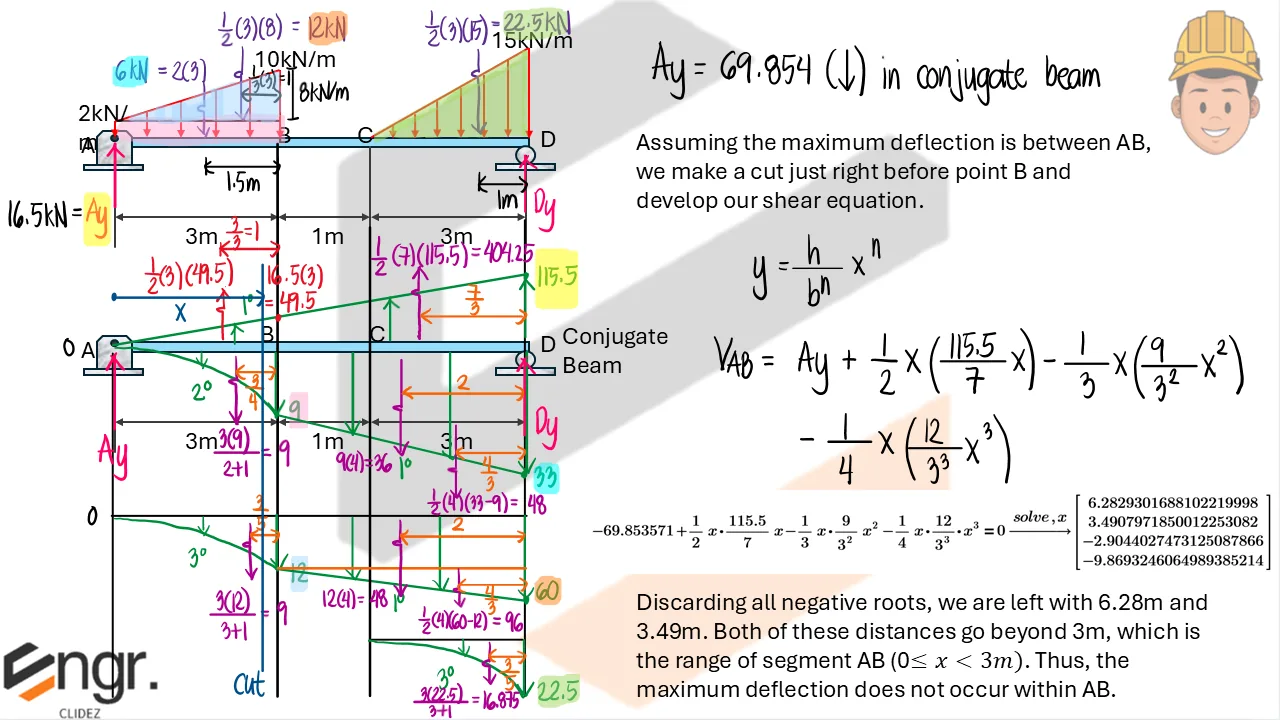
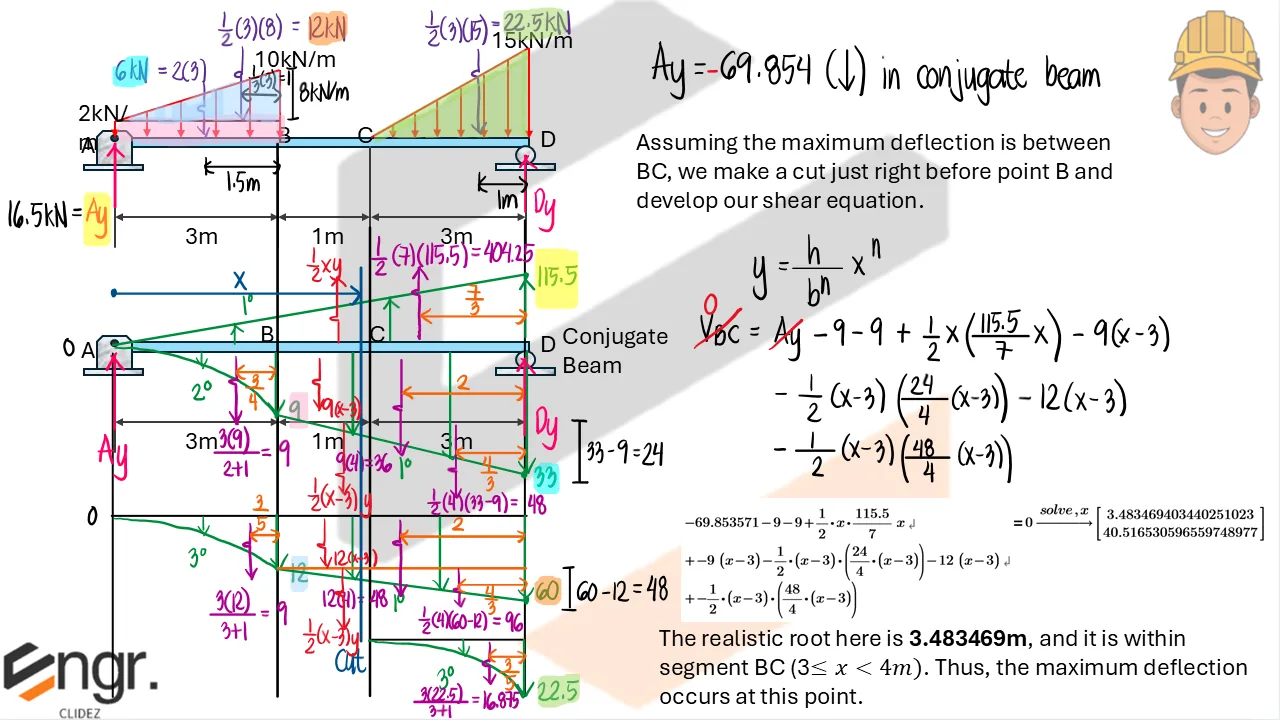
- Theorem 1: The slope at a point in the real beam is equal to the shear at the corresponding point in the conjugate beam, i.e., $V_{\text{conj}} = \theta_{\text{real}}$.
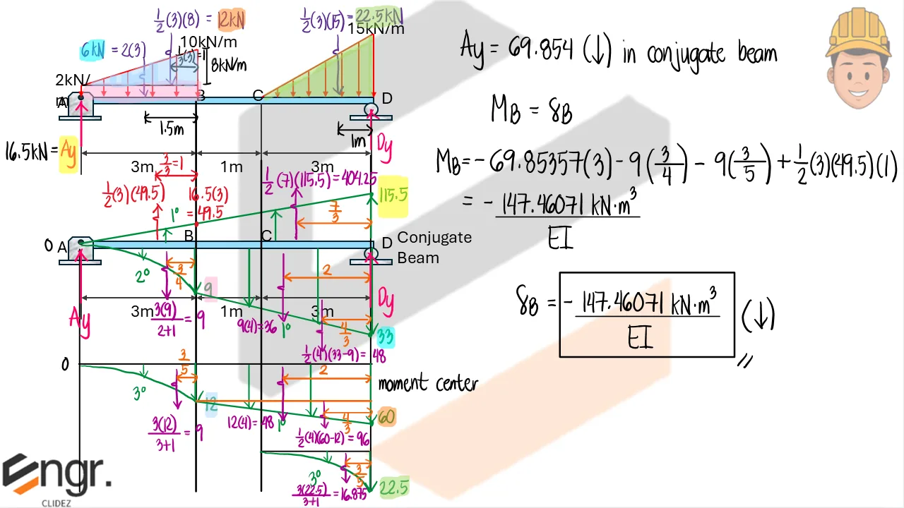
- Theorem 2: The deflection at a point in the real beam is equal to the moment at the corresponding point in the conjugate beam, i.e., $M_{\text{conj}} = y_{\text{real}}$.
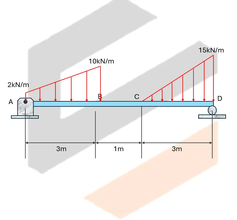
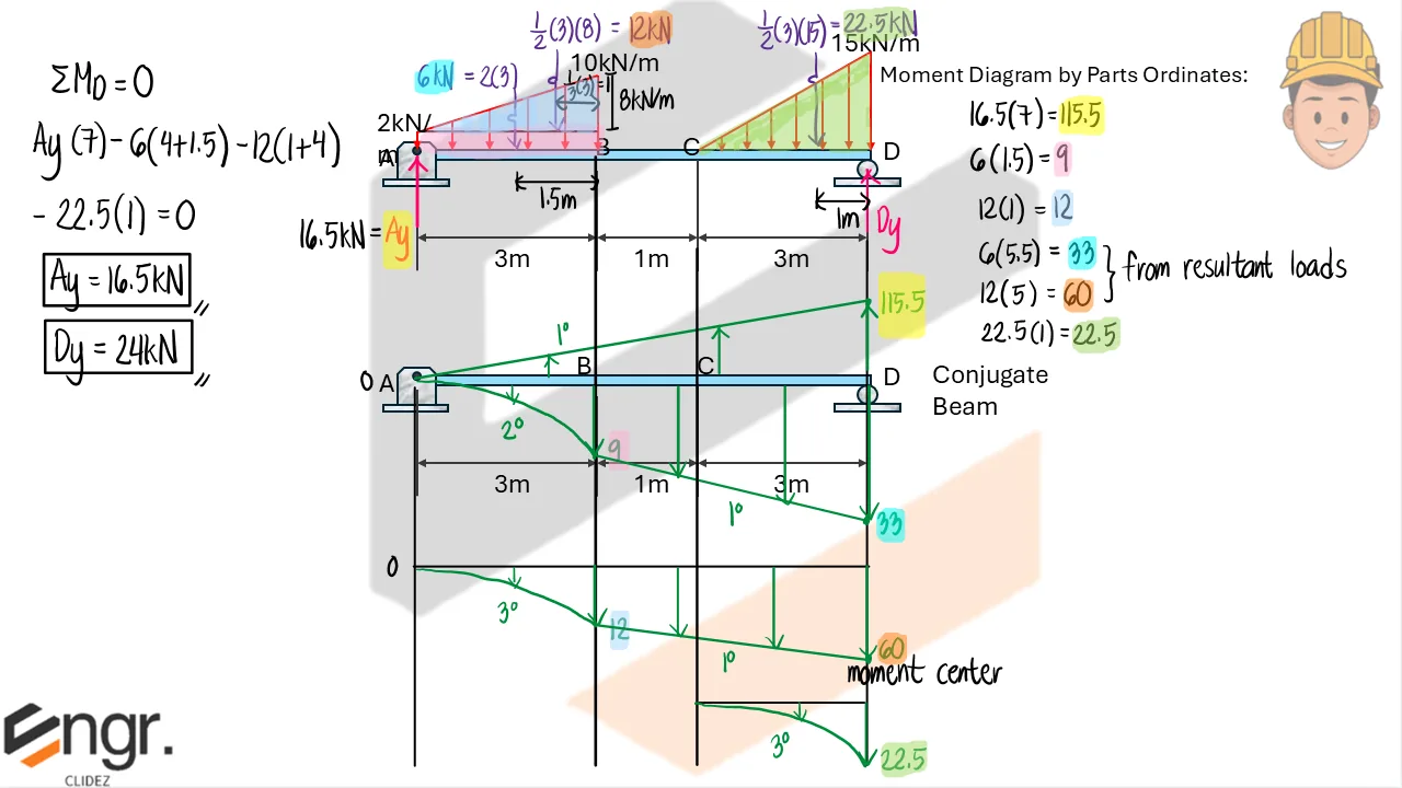
The real beam is the actual structure under load. The conjugate beam is a hypothetical beam loaded with the moment diagram divided by $EI$, and its support conditions are chosen to reflect the slope and deflection behavior of the real beam.
Important: The resulting conjugate beam may be statically unstable from a structural perspective — for example, a real beam with fixed supports at both ends will lead to a conjugate beam with free ends. Despite appearing unstable, the conjugate beam must be solved as-is because it reflects the correct mathematical relationships between slope and deflection in the real beam.
Key idea: The supports of the conjugate beam must be modified so that:
- If the real beam has zero slope at a point, the conjugate beam must have zero shear at that point.
- If the real beam has zero deflection at a point, the conjugate beam must have zero moment at that point.
By designing the conjugate beam accordingly and applying the moment/$EI$ diagram as loading, we can compute the slope and deflection in the real beam by analyzing the shear and moment values in the conjugate beam.
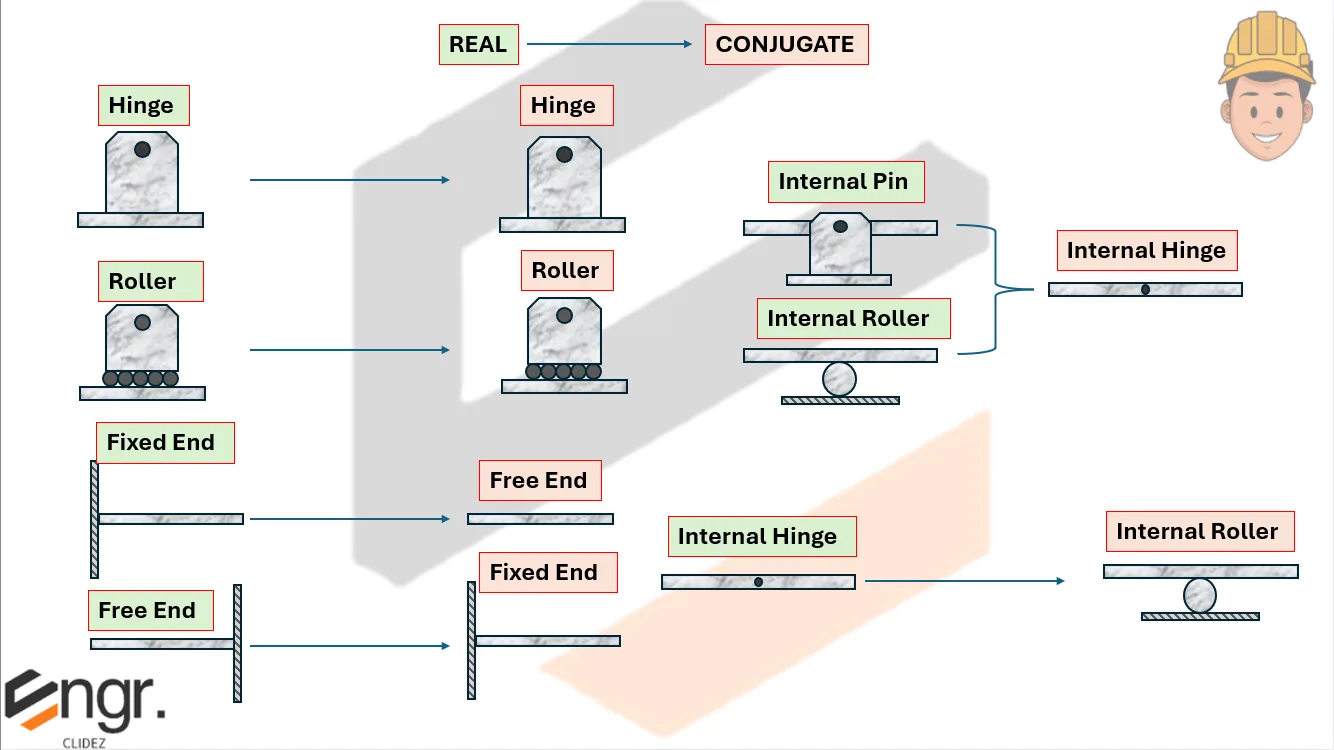
Conjugate Beam Support Equivalents
| Real Beam Support | Slope $\theta$ | Deflection $y$ | Conjugate Beam Support | Conjugate Shear $V$ | Conjugate Moment $M$ |
|---|---|---|---|---|---|
| Fixed End | $\theta = 0$ | $y = 0$ | Free End | $V = 0$ | $M = 0$ |
| Free End | $\theta \ne 0$ | $y \ne 0$ | Fixed End | $V \ne 0$ | $M \ne 0$ |
| Hinge | $\theta \ne 0$ | $y = 0$ | Hinge | $V \ne 0$ | $M = 0$ |
| Roller | $\theta \ne 0$ | $y = 0$ | Roller | $V \ne 0$ | $M = 0$ |
| Internal Pin | $\theta \ne 0$ | $y = 0$ | Internal Hinge | $V \ne 0$ | $M = 0$ |
| Internal Roller | $\theta \ne 0$ | $y = 0$ | Internal Hinge | $V \ne 0$ | $M = 0$ |
| Internal Hinge | $\theta \ne 0$ | $y \ne 0$ | Internal Roller | $V \ne 0$ | $M \ne 0$ |
General rule: If a real support allows a slope, the conjugate support must develop a shear, and if the real support allows a displacement, the conjugate support must develop a moment.