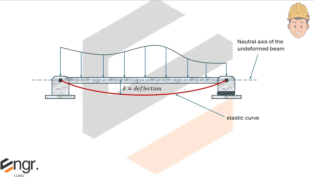
Beam deflection refers to the displacement of a structural element under load. Understanding how beams bend and deform is essential for ensuring structural safety and serviceability. In engineering, various methods are used to calculate beam deflections, each suited for specific types of loads, supports, and material behavior. One fundamental method is the Double Integration Method, which uses calculus and moment equations to determine the slope and deflection along the length of the beam.
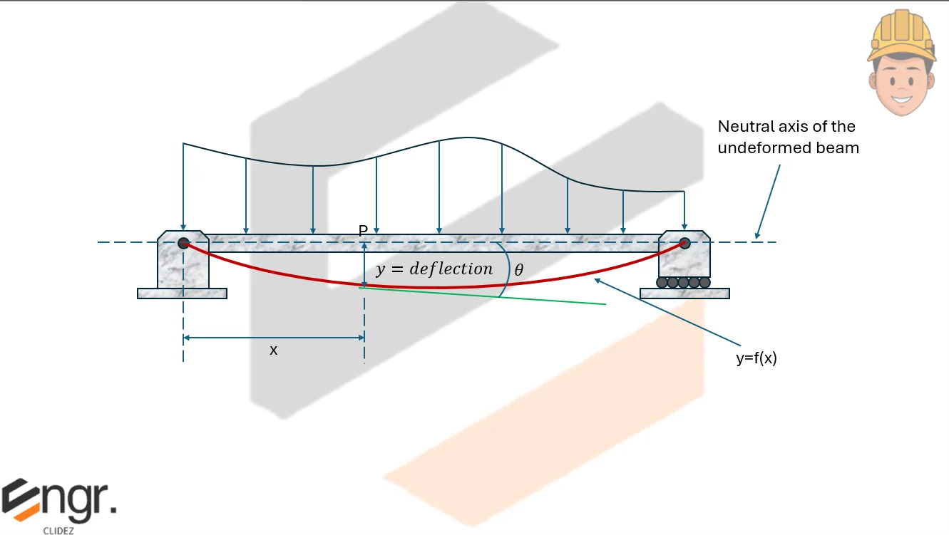
Setting the left end as the origin for the beam, at point \( P \), a distance \( x \) from the origin, the deflection is \( y \) and the slope of the elastic curve is \( \theta \).
Let \( y = f(x) \) be the equation of the elastic curve. From calculus, the radius of curvature of a curve \( y = f(x) \) is given by the formula:
From Strength of Materials, the radius of curvature of the beam subjected to bending is:
\[
\rho = \dfrac{EI}{M}
\]
Equating the two expressions for \( \rho \), we have:
\[
\dfrac{EI}{M} = \dfrac{1}{y''}
\]
or
\[
EI \cdot y'' = M
\]
Equation above is known as the differential equation of the elastic curve.
Where:
\( E \) = modulus of elasticity of the beam material
\( I \) = moment of inertia of the beam cross-section
\( EI \) = flexural rigidity (product of \( E \) and \( I \))
\( M \) = bending moment at the point \( P \)
The first integration gives:
\[
EI \cdot y' = \int M \, dx + C_1
\]
This is the slope equation. Note that \( \tan \theta = \dfrac{dy}{dx} \), but for small angles, \( \tan \theta \approx \theta \), thus:
\[
\theta = \dfrac{dy}{dx}
\]
Note that \( \theta \) is also the rotation of the beam at the given point.
The second integration gives:
\[
EI \cdot y = \iint M \, dx \, dx + C_1 x + C_2
\]
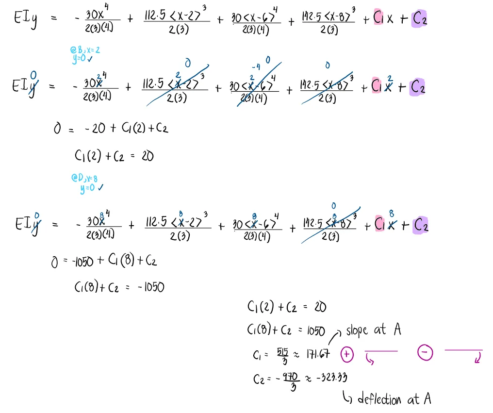
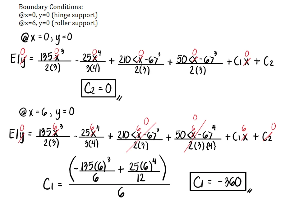
This is called the deflection equation, where \( C_1 \) and \( C_2 \) are constants of integration that can be solved using known boundary conditions.
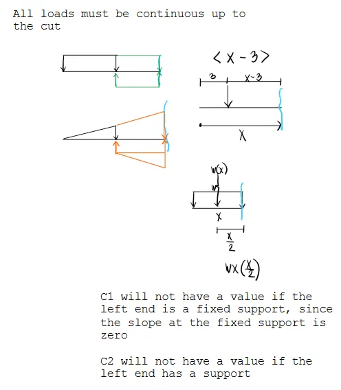
Macaulay bracket reminder: A Macaulay bracket term is never allowed to become negative. If the section is before the load or discontinuity, the bracket term is taken as zero. If the section is at or beyond the load or discontinuity, use the positive distance from that point.
$$ \langle x-a\rangle=0 \quad \text{when } x \lt a $$
$$ \langle x-a\rangle=x-a \quad \text{when } x \ge a $$
For example, if a point load starts at x = 9 m, then ⟨x - 9⟩ = 0 for sections between 0 m and 9 m. For sections beyond 9 m, use ⟨x - 9⟩ = x - 9. This is why roots or trial locations must be checked against the segment where the equation was written.
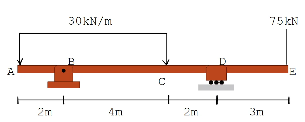
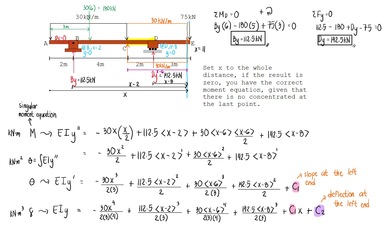
Problem:
For the beam shown, determine:
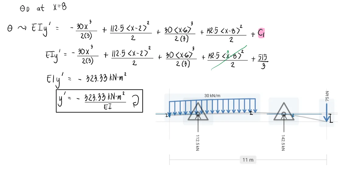
a. The slope at point D
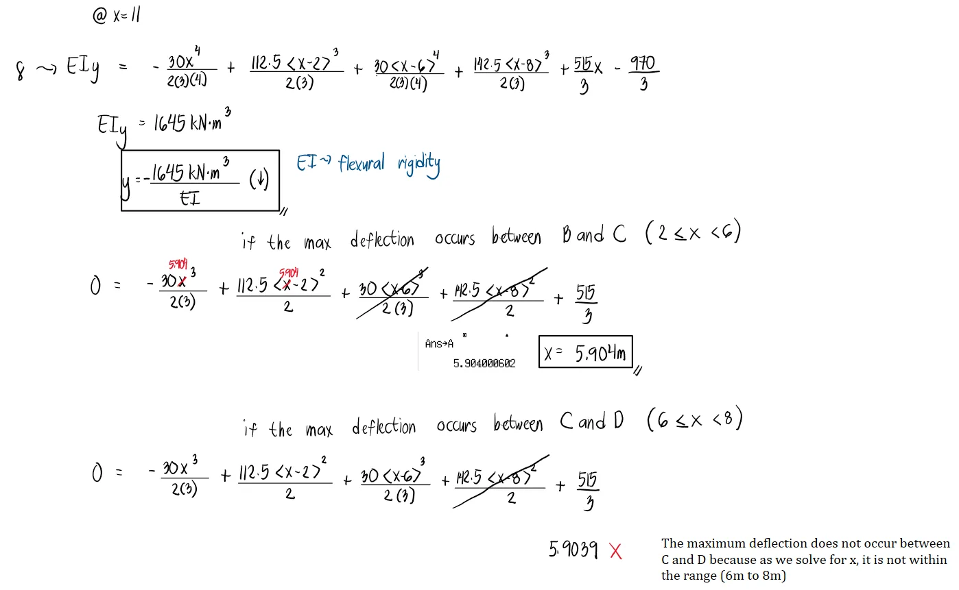
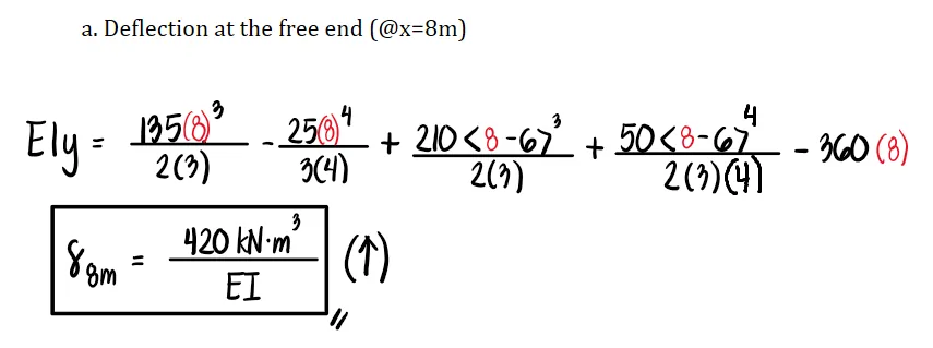
b. The deflection at the free end (point E)
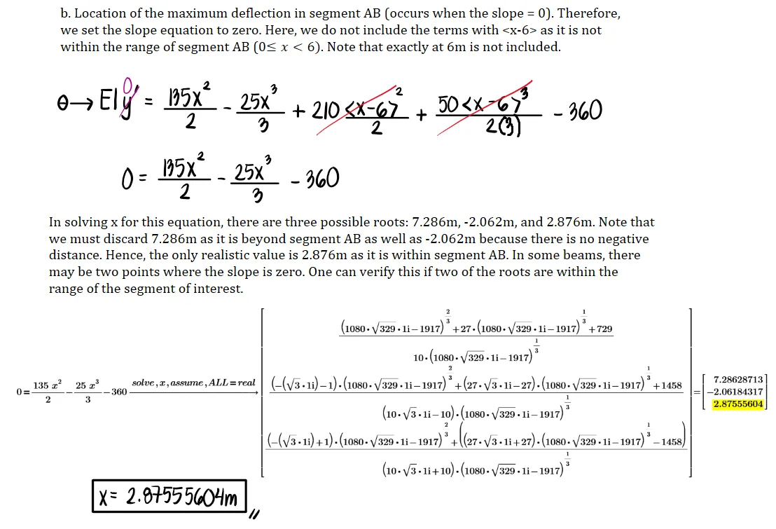
c. The location of the maximum deflection midway between B and D
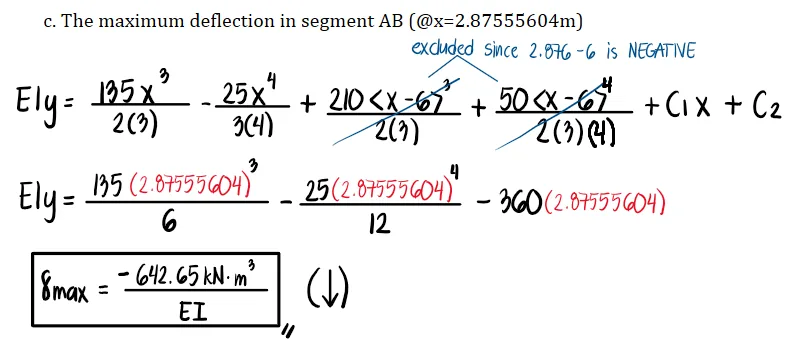
d. The value of the maximum deflection considering the previous question
See images:
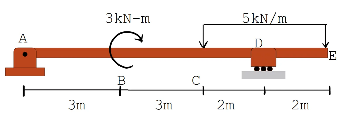
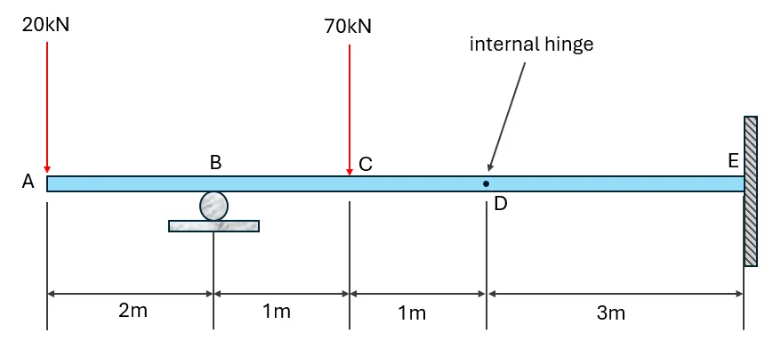
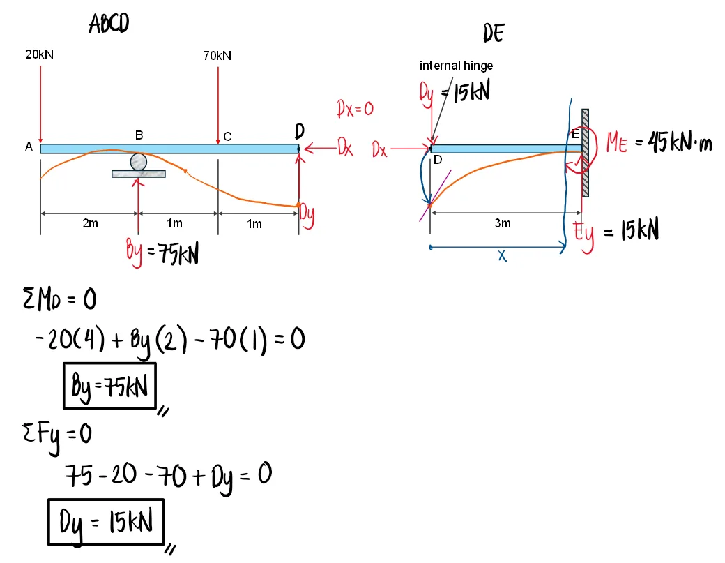
Problem:
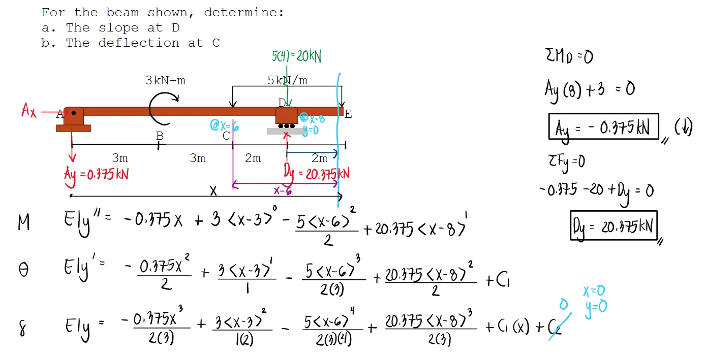
For the beam shown, determine:
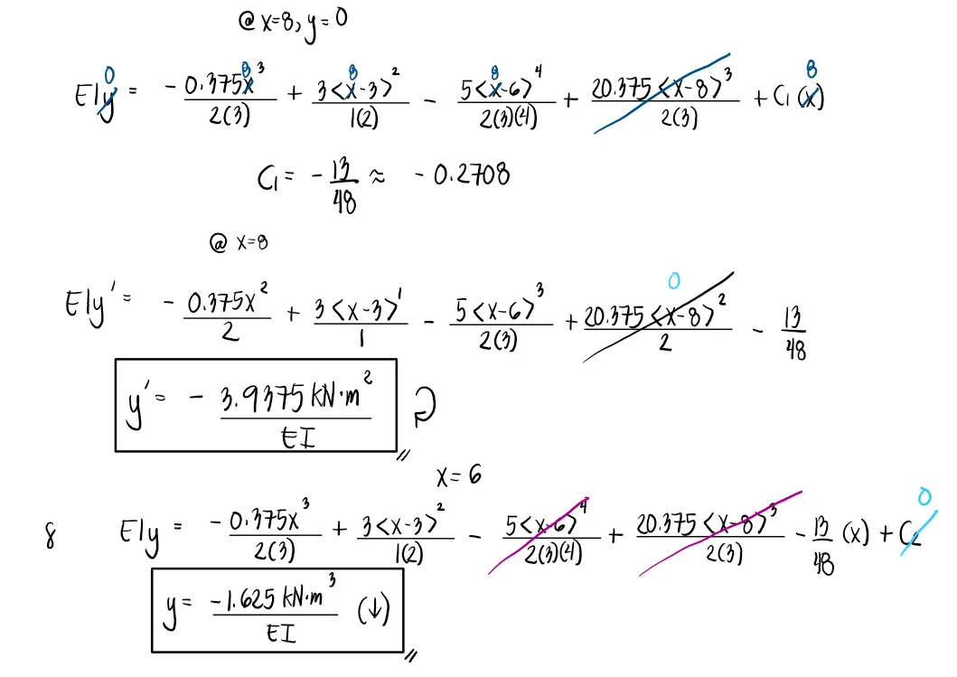
a. The slope at D
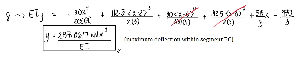
b. The deflection at C
See images:
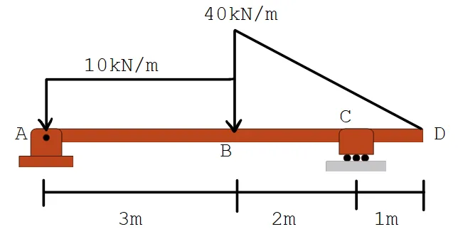
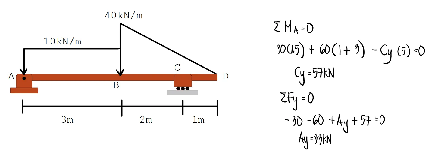
Problem:
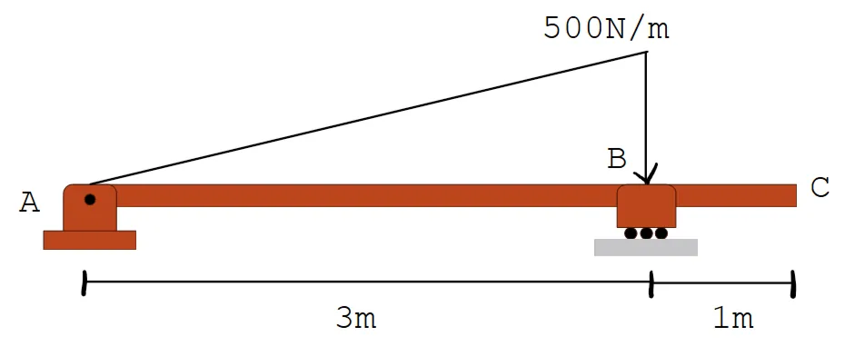
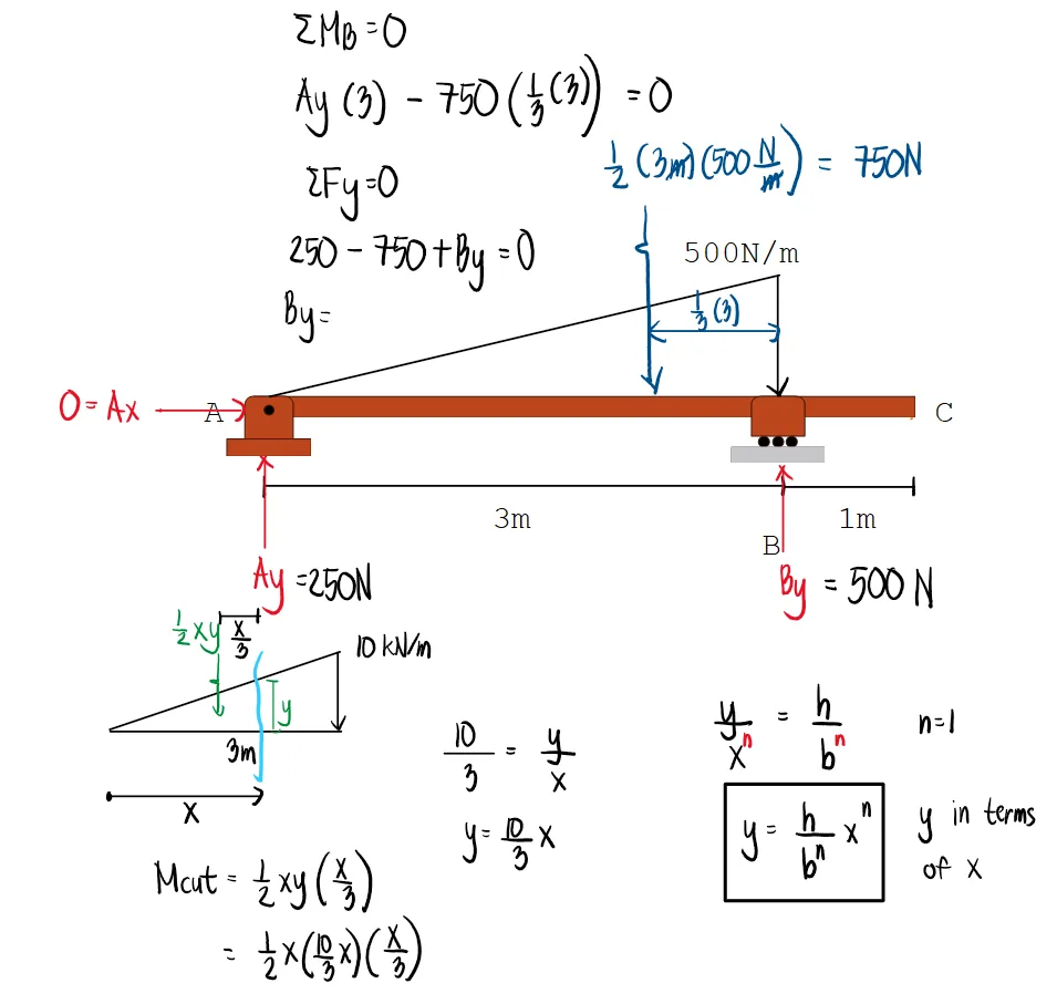
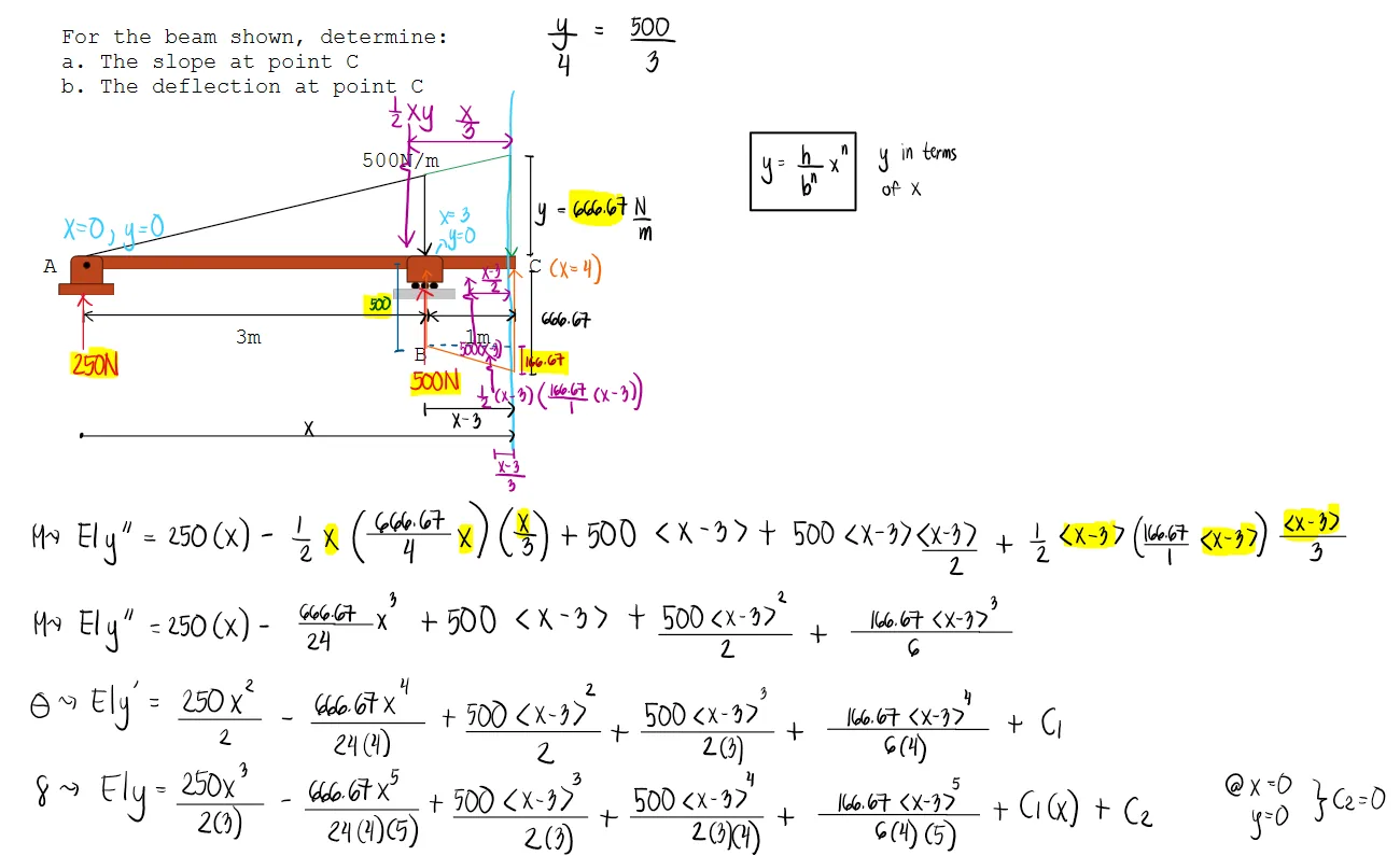
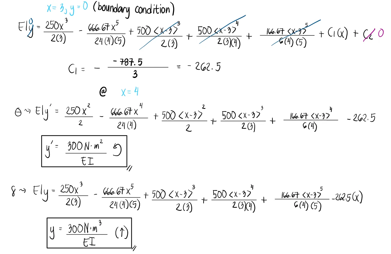
For the beam shown, determine:
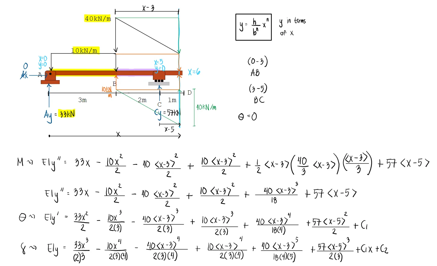
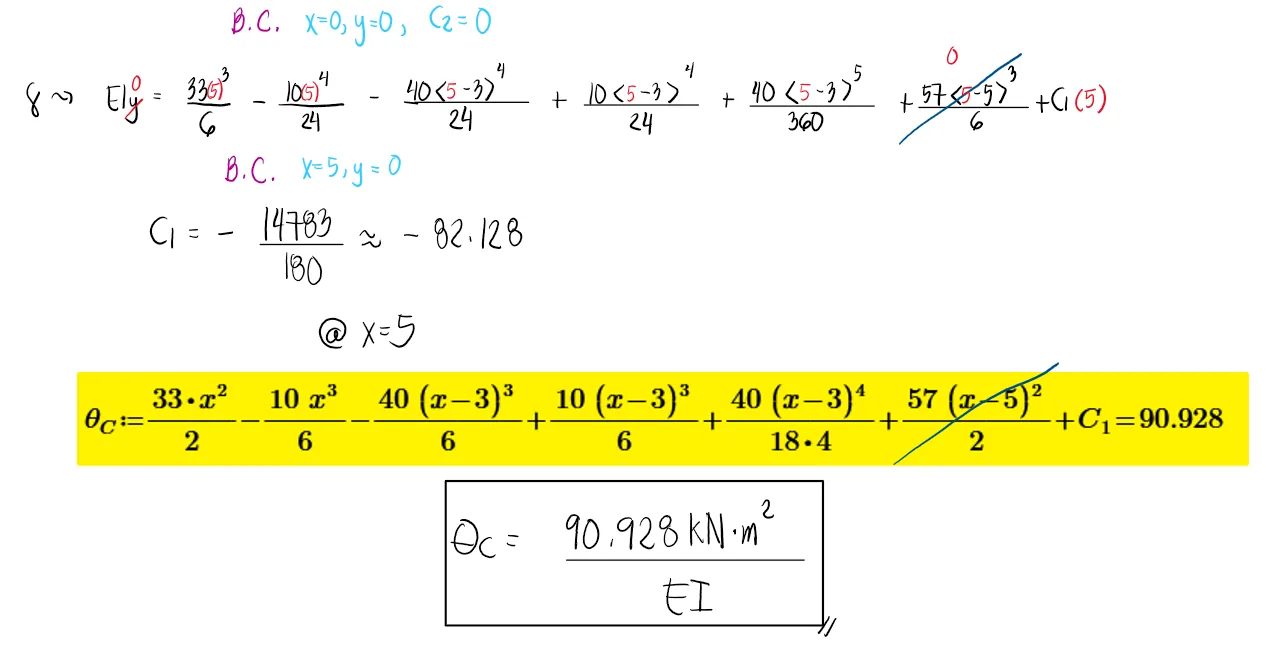
a. The slope at point C
b. The deflection at point C
See images:
Problem:
For the beam shown, determine:
a. The slope at point C
b. The deflection at the free end
c. The location and value of the maximum deflection midway between AC
See images:
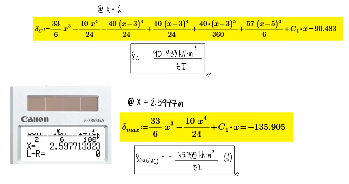
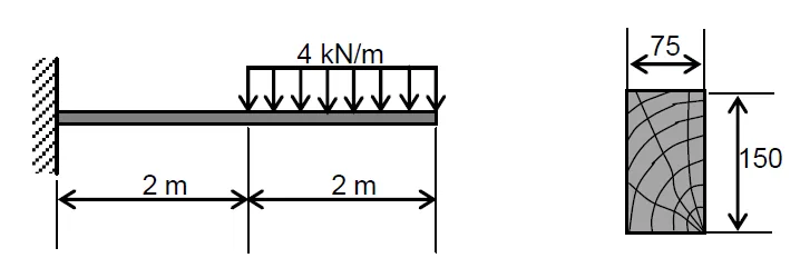
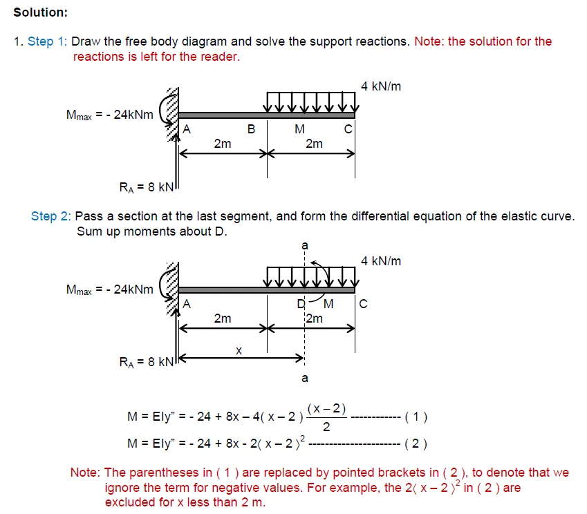
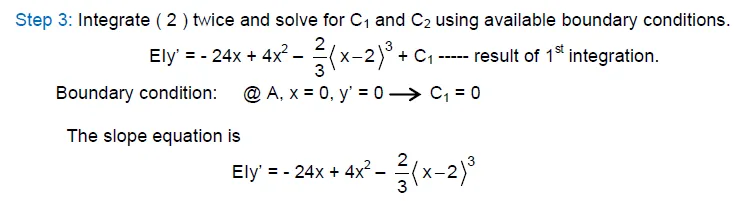
Problem:
Problem by Engr. Edwin Rosalena
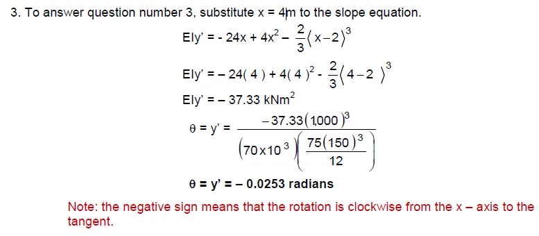
a. For the beam shown, compute the deflection at a point 2m from the left support.
b. Compute the maximum deflection.
c. Compute the slope (rotation) at the free end.
See images:
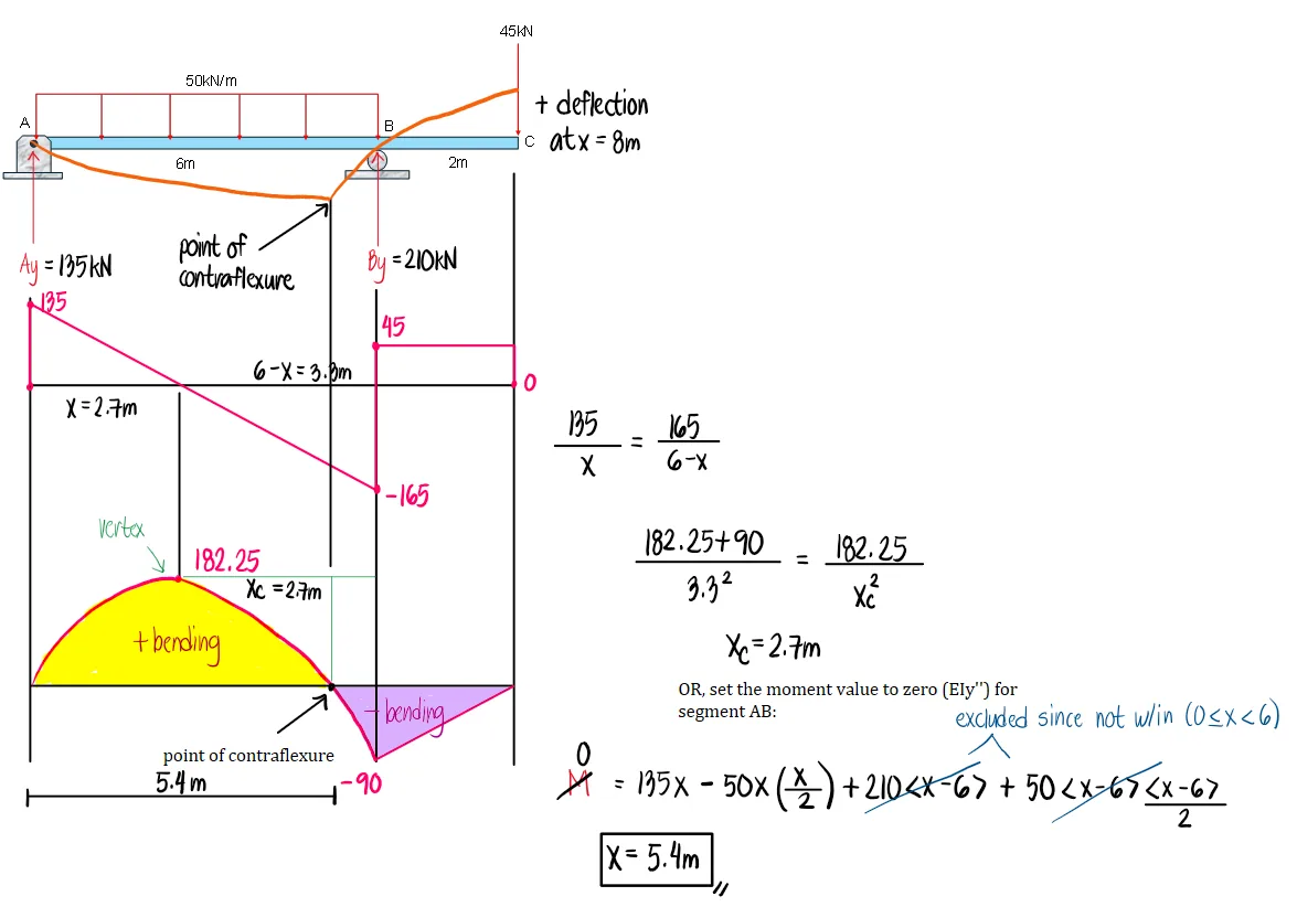
Problem:
For the beam shown,
a. Determine the deflection at the free end.
b. Determine the location of the maximum deflection.
c. Determine the maximum deflection.
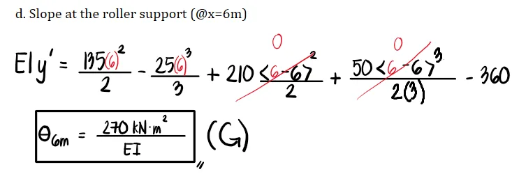
d. Determine the slope at the roller support.
See images:
Problem:
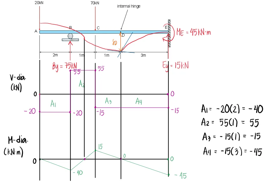
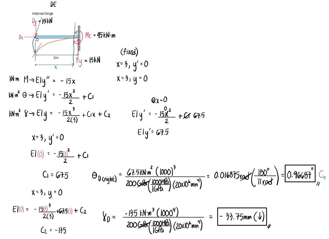
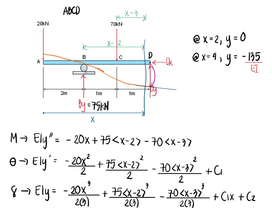
For the beam shown, use E = 200GPa and I = 20x106mm4. Draw the shear and moment diagram as well as the elastic curve.
a. Compute the deflection at D (in mm).
b. Compute the deflection at A (in mm).
c. Compute the left and right slope values at D (in degrees).
See images:
Problem:
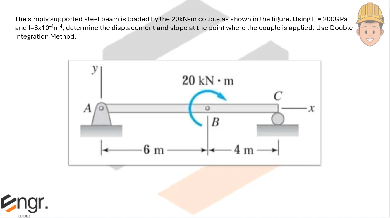
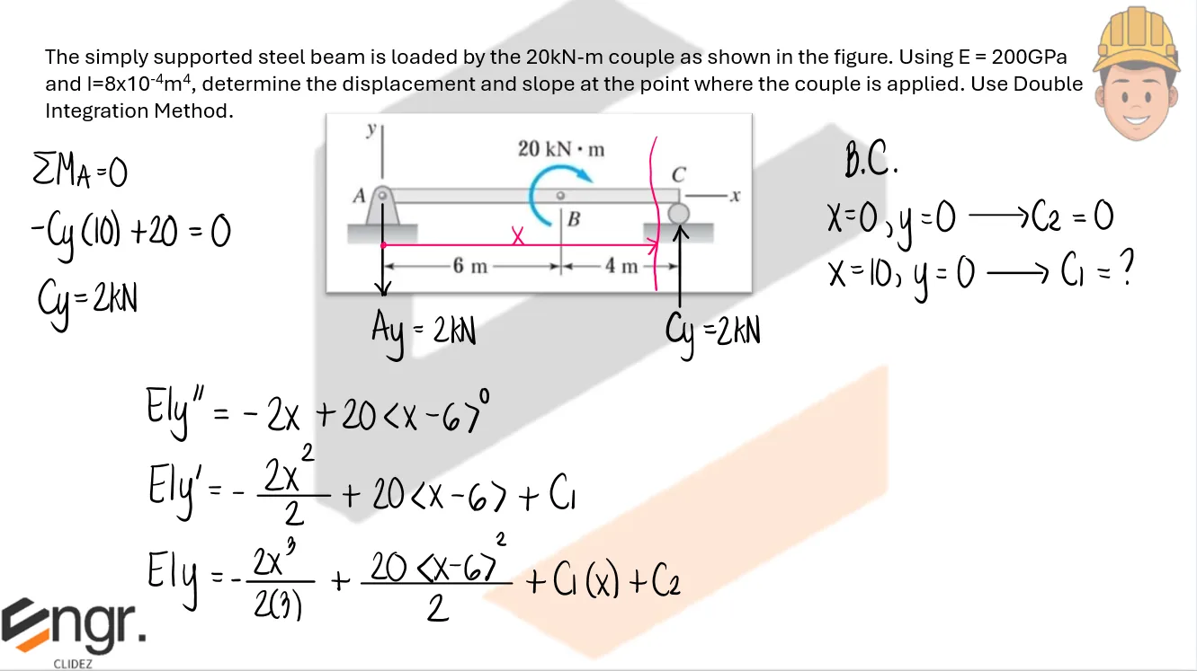
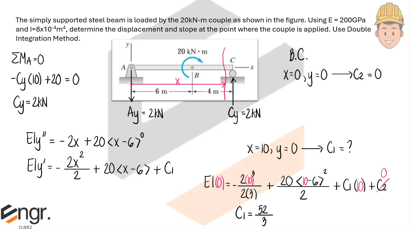
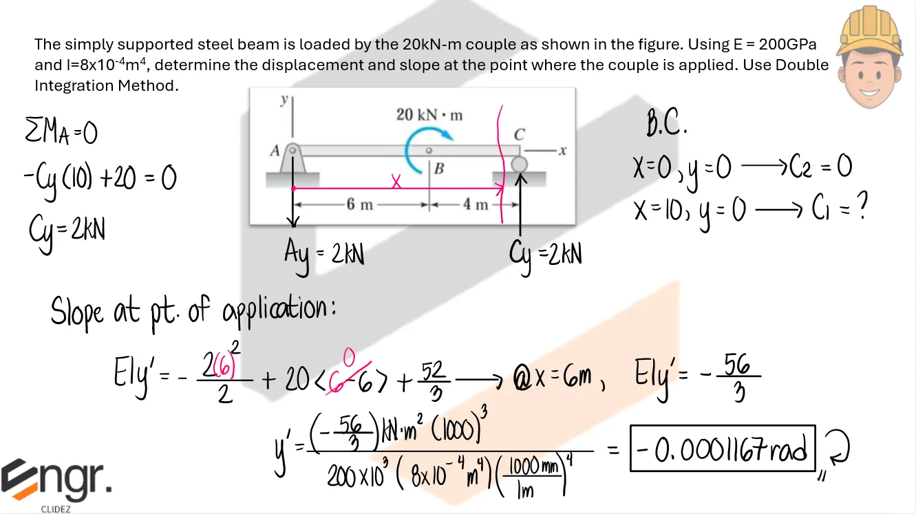
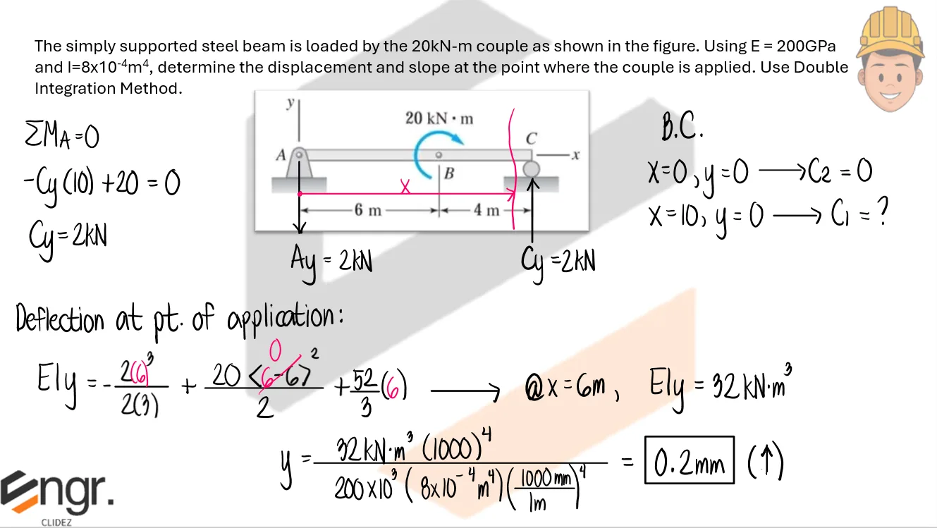
The simply supported steel beam is loaded by the 20kN-m couple as shown in the figure. Using E = 200GPa and I=8x10⁻⁴m4, determine the displacement and slope at the point where the couple is applied. Use Double Integration Method.
See images:
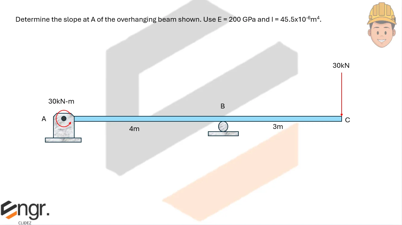
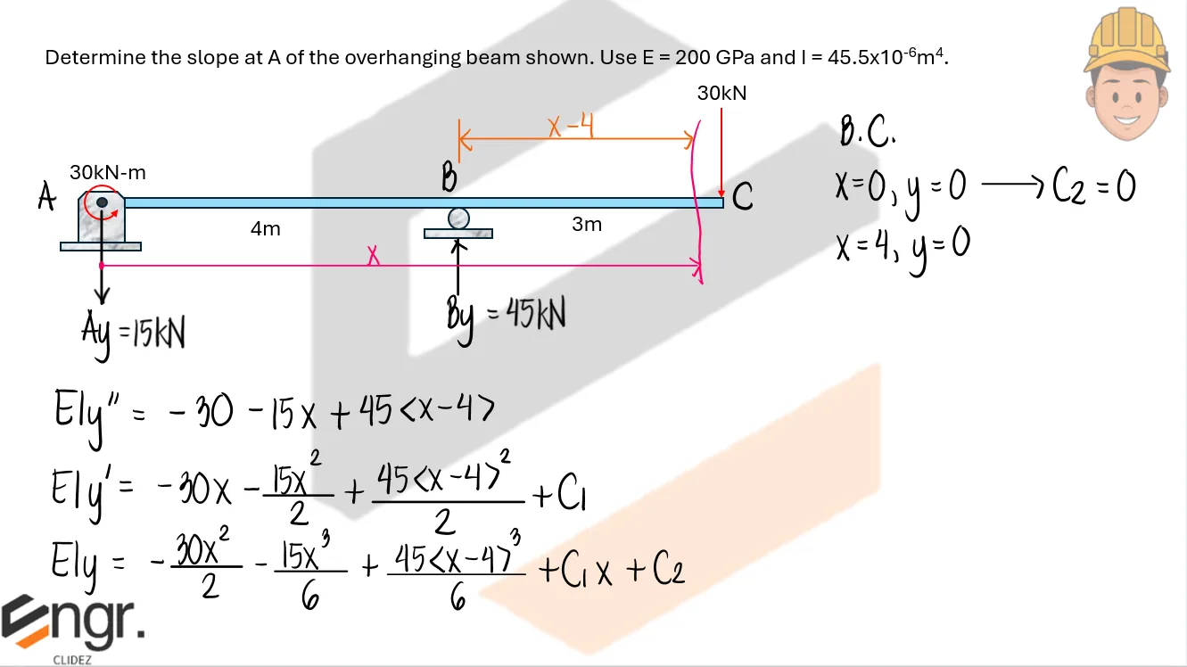
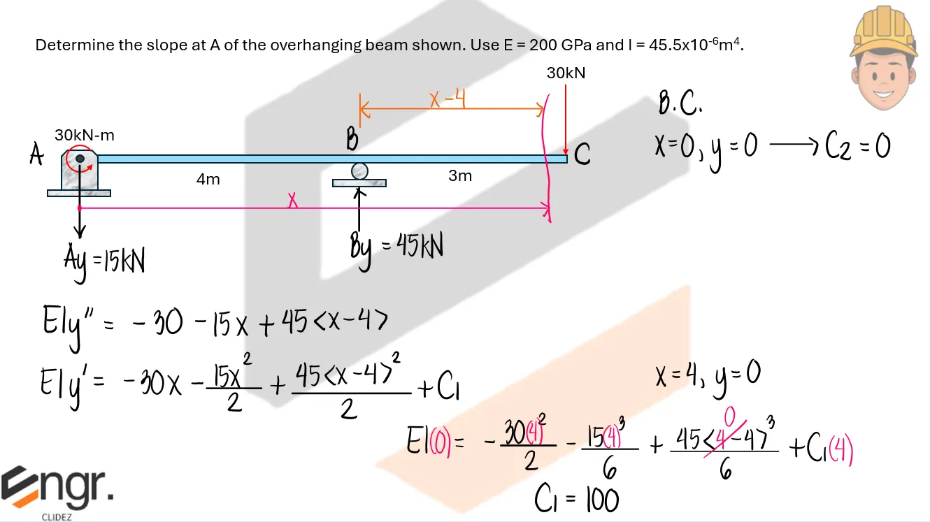
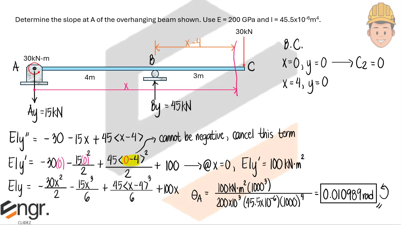
Problem:
Determine the slope at A of the overhanging beam shown. Use E = 200GPa and I = 45.5x10⁻⁶mm4
See images:
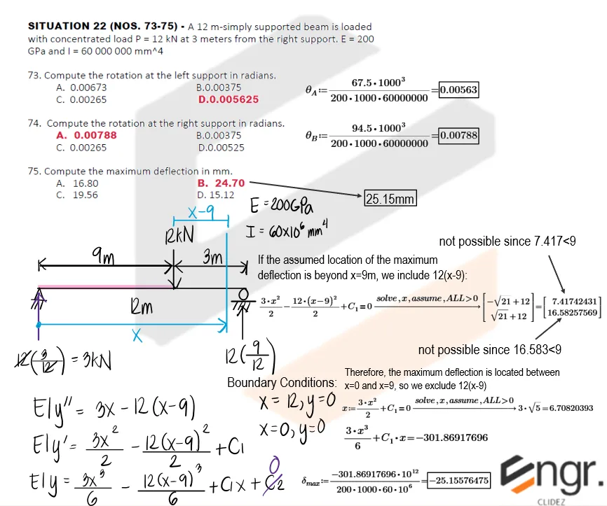
Problem: Simply Supported Beam with Eccentric Point Load
A 12 m simply supported beam is loaded with concentrated load P = 12 kN at 3 meters from the right support. E = 200 GPa and I = 60 000 000 mm4.
Compute the rotation at the left support in radians.
0.00673
0.00375
0.00265
0.005625
Compute the rotation at the right support in radians.
0.00788
0.00375
0.00265
0.00525
Compute the maximum deflection in mm.
16.80
25.15
19.56
The load is 3 m from the right support, so it is 9 m from the left support. The reactions are:
For a section at distance x from the left support, use Macaulay brackets for the point load at x = 9 m. The term ⟨x - 9⟩ is zero before the load and becomes x - 9 after the load.
The support rotations are obtained from the slope equation. With the sign convention used here, a positive slope means counterclockwise rotation from the horizontal, while a negative slope means clockwise rotation from the horizontal.
Thus, the left support rotates 0.005625 rad clockwise, and the right support rotates 0.00788 rad counterclockwise. The answer choices list the absolute value of the rotations.
Maximum deflection occurs where slope is zero. Because the load is at x = 9 m, check the possible locations by segment. First check the segment from x = 0 to x = 9 m, where the Macaulay term is not active.
For this second segment, neither root is acceptable: x = 7.417 m is less than 9 m, so it does not belong to the segment being checked, and x = 16.58 m is beyond the 12 m beam span. Since the right-hand segment gives no valid root, use the valid candidate from the first segment: x = 6.708 m.
The negative sign means the maximum deflection is downward according to the assumed sign convention. The answer choices use the magnitude, so report 25.15 mm.
Final answers: a. D. 0.005625; b. A. 0.00788; c. B. 25.15 mm