CE Board Exam Randomizer

⬅ Back to Subject Topics

Analysis of Frames

Frames are structural systems composed of multiple members connected together, typically to support various types of loads. In this section, we will begin by analyzing pin-connected frames — similar in form to trusses but capable of carrying more complex loading scenarios.

Pin-connected frames may carry axial forces like trusses, but they can also transmit external loads applied between joints, making their analysis slightly more involved. We'll still rely on the basic principles of statics discussed in the Statics of Rigid Bodies section, including the following equations:

\[ \sum F_x = 0, \quad \sum F_y = 0, \quad \sum M = 0 \]

Later on, we will also tackle rigid frames — those with members connected by rigid joints, capable of resisting axial forces, shear forces, and bending moments. These types of frames require more advanced techniques for analysis, especially when they become statically indeterminate.

Concept Concept Concept Concept Concept Concept Concept Concept Concept

Problem: CE Past Board Exam

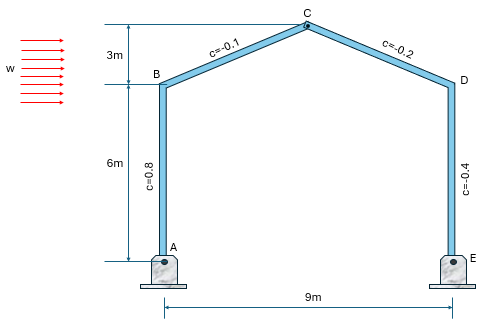
The representative frame shown below is subjected to a wind pressure of 1.5kPa. The frames are spaced 6m apart and the coefficients of wind pressure are given for each member as shown. Assume that A and E are hinged and that C is pin-connected. Solve the reactions and draw the shear, moment, and axial diagrams of each member.

Analysis of Pin-connected and Rigid Frames: Shear, Moment, and Axial Diagram | Structural Theory – Problem 1: – Diagram Analysis of Pin-connected and Rigid Frames: Shear, Moment, and Axial Diagram | Structural Theory – Problem 1: – Diagram Analysis of Pin-connected and Rigid Frames: Shear, Moment, and Axial Diagram | Structural Theory – Problem 1: – Diagram

The wind pressure is first converted into equivalent uniformly distributed loads on each member by multiplying it by the frame spacing. A positive wind pressure coefficient indicates that the load acts toward the member, whereas a negative coefficient represents a suction effect, causing the load to act away from the member (see the directions of the load on member CD and DE).

Analysis of Pin-connected and Rigid Frames: Shear, Moment, and Axial Diagram | Structural Theory – Problem 1: – Diagram

A useful technique in solving the reactions when there are distributed loads acting perpendicular to the inclined members of a frame is to split the load into two uniformly distributed loads acting over the horizontal and vertical components of the distances.

For example, the 2kN/m and 5kN/m uniform loads acting on BC and CD are broken into two separate loading acting over the 4-m horizontal distance and the 3-m vertical distance.

We only revert this once we draw the shear, moment, and axial diagrams since we generally want the external loads to act perpendicular to the member.

Analysis of Pin-connected and Rigid Frames: Shear, Moment, and Axial Diagram | Structural Theory – Problem 1: – Diagram

In our solution, we combine the forces with the same moment arms. For example, the 30kN resultant on AB and the 15kN resultant on DE each have a moment arm of 2.5m about point E, so we join the two as (30+15) multiplied by the common moment arm. Note that we still follow our sign convention here. Both the 30kN and 15kN loads cause a clockwise rotation about point E, so we use a positive sign for both. In the case where, for example, the 15kN load will cause a counterclockwise rotation, we use (30-15) multiplied by the moment arm.

Analysis of Pin-connected and Rigid Frames: Shear, Moment, and Axial Diagram | Structural Theory – Problem 1: – Diagram Analysis of Pin-connected and Rigid Frames: Shear, Moment, and Axial Diagram | Structural Theory – Problem 1: – Diagram Analysis of Pin-connected and Rigid Frames: Shear, Moment, and Axial Diagram | Structural Theory – Problem 1: – Diagram

For the purpose of uniformity, we draw our shear, moment, and axial diagrams from top to bottom or left to right and use rotated reference axes for inclined members (BC and CD). We must also obtain the components of the original external and internal reactions along the rotated axes.

Analysis of Pin-connected and Rigid Frames: Shear, Moment, and Axial Diagram | Structural Theory – Problem 1: – Diagram Analysis of Pin-connected and Rigid Frames: Shear, Moment, and Axial Diagram | Structural Theory – Problem 1: – Diagram Analysis of Pin-connected and Rigid Frames: Shear, Moment, and Axial Diagram | Structural Theory – Problem 1: – Diagram Analysis of Pin-connected and Rigid Frames: Shear, Moment, and Axial Diagram | Structural Theory – Problem 1: – Diagram Analysis of Pin-connected and Rigid Frames: Shear, Moment, and Axial Diagram | Structural Theory – Problem 1: – Diagram Analysis of Pin-connected and Rigid Frames: Shear, Moment, and Axial Diagram | Structural Theory – Problem 1: – Diagram

Problem:

Refer to the image shown:

Analysis of Pin-connected and Rigid Frames: Shear, Moment, and Axial Diagram | Structural Theory – Problem 2: – Diagram Analysis of Pin-connected and Rigid Frames: Shear, Moment, and Axial Diagram | Structural Theory – Problem 2: – Diagram Analysis of Pin-connected and Rigid Frames: Shear, Moment, and Axial Diagram | Structural Theory – Problem 2: – Diagram

See images:

Analysis of Pin-connected and Rigid Frames: Shear, Moment, and Axial Diagram | Structural Theory – Problem 2: – Diagram Analysis of Pin-connected and Rigid Frames: Shear, Moment, and Axial Diagram | Structural Theory – Problem 2: – Diagram Analysis of Pin-connected and Rigid Frames: Shear, Moment, and Axial Diagram | Structural Theory – Problem 2: – Diagram Analysis of Pin-connected and Rigid Frames: Shear, Moment, and Axial Diagram | Structural Theory – Problem 2: – Diagram

Problem:

Refer to the image shown:

Analysis of Pin-connected and Rigid Frames: Shear, Moment, and Axial Diagram | Structural Theory – Problem 3: – Diagram Analysis of Pin-connected and Rigid Frames: Shear, Moment, and Axial Diagram | Structural Theory – Problem 3: – Diagram Analysis of Pin-connected and Rigid Frames: Shear, Moment, and Axial Diagram | Structural Theory – Problem 3: – Diagram

See images:

Analysis of Pin-connected and Rigid Frames: Shear, Moment, and Axial Diagram | Structural Theory – Problem 3: – Diagram Analysis of Pin-connected and Rigid Frames: Shear, Moment, and Axial Diagram | Structural Theory – Problem 3: – Diagram Analysis of Pin-connected and Rigid Frames: Shear, Moment, and Axial Diagram | Structural Theory – Problem 3: – Diagram Analysis of Pin-connected and Rigid Frames: Shear, Moment, and Axial Diagram | Structural Theory – Problem 3: – Diagram

Problem:

Refer to the image shown:

Analysis of Pin-connected and Rigid Frames: Shear, Moment, and Axial Diagram | Structural Theory – Problem 4: – Diagram Analysis of Pin-connected and Rigid Frames: Shear, Moment, and Axial Diagram | Structural Theory – Problem 4: – Diagram Analysis of Pin-connected and Rigid Frames: Shear, Moment, and Axial Diagram | Structural Theory – Problem 4: – Diagram

See images:

Analysis of Pin-connected and Rigid Frames: Shear, Moment, and Axial Diagram | Structural Theory – Problem 4: – Diagram Analysis of Pin-connected and Rigid Frames: Shear, Moment, and Axial Diagram | Structural Theory – Problem 4: – Diagram Analysis of Pin-connected and Rigid Frames: Shear, Moment, and Axial Diagram | Structural Theory – Problem 4: – Diagram Analysis of Pin-connected and Rigid Frames: Shear, Moment, and Axial Diagram | Structural Theory – Problem 4: – Diagram

Problem:

Refer to the image shown:

Analysis of Pin-connected and Rigid Frames: Shear, Moment, and Axial Diagram | Structural Theory – Problem 5: – Diagram Analysis of Pin-connected and Rigid Frames: Shear, Moment, and Axial Diagram | Structural Theory – Problem 5: – Diagram Analysis of Pin-connected and Rigid Frames: Shear, Moment, and Axial Diagram | Structural Theory – Problem 5: – Diagram

See images:

Analysis of Pin-connected and Rigid Frames: Shear, Moment, and Axial Diagram | Structural Theory – Problem 5: – Diagram Analysis of Pin-connected and Rigid Frames: Shear, Moment, and Axial Diagram | Structural Theory – Problem 5: – Diagram Analysis of Pin-connected and Rigid Frames: Shear, Moment, and Axial Diagram | Structural Theory – Problem 5: – Diagram Analysis of Pin-connected and Rigid Frames: Shear, Moment, and Axial Diagram | Structural Theory – Problem 5: – Diagram

Problem:

Refer to the image shown:

Analysis of Pin-connected and Rigid Frames: Shear, Moment, and Axial Diagram | Structural Theory – Problem 6: – Diagram Analysis of Pin-connected and Rigid Frames: Shear, Moment, and Axial Diagram | Structural Theory – Problem 6: – Diagram Analysis of Pin-connected and Rigid Frames: Shear, Moment, and Axial Diagram | Structural Theory – Problem 6: – Diagram

See images:

Analysis of Pin-connected and Rigid Frames: Shear, Moment, and Axial Diagram | Structural Theory – Problem 6: – Diagram Analysis of Pin-connected and Rigid Frames: Shear, Moment, and Axial Diagram | Structural Theory – Problem 6: – Diagram Analysis of Pin-connected and Rigid Frames: Shear, Moment, and Axial Diagram | Structural Theory – Problem 6: – Diagram Analysis of Pin-connected and Rigid Frames: Shear, Moment, and Axial Diagram | Structural Theory – Problem 6: – Diagram

Problem:

Refer to the image shown:

Analysis of Pin-connected and Rigid Frames: Shear, Moment, and Axial Diagram | Structural Theory – Problem 7: – Diagram Analysis of Pin-connected and Rigid Frames: Shear, Moment, and Axial Diagram | Structural Theory – Problem 7: – Diagram Analysis of Pin-connected and Rigid Frames: Shear, Moment, and Axial Diagram | Structural Theory – Problem 7: – Diagram

See images:

Analysis of Pin-connected and Rigid Frames: Shear, Moment, and Axial Diagram | Structural Theory – Problem 7: – Diagram Analysis of Pin-connected and Rigid Frames: Shear, Moment, and Axial Diagram | Structural Theory – Problem 7: – Diagram Analysis of Pin-connected and Rigid Frames: Shear, Moment, and Axial Diagram | Structural Theory – Problem 7: – Diagram Analysis of Pin-connected and Rigid Frames: Shear, Moment, and Axial Diagram | Structural Theory – Problem 7: – Diagram

Problem:

Refer to the image shown:

Analysis of Pin-connected and Rigid Frames: Shear, Moment, and Axial Diagram | Structural Theory – Problem 8: – Diagram Analysis of Pin-connected and Rigid Frames: Shear, Moment, and Axial Diagram | Structural Theory – Problem 8: – Diagram Analysis of Pin-connected and Rigid Frames: Shear, Moment, and Axial Diagram | Structural Theory – Problem 8: – Diagram

See images:

Analysis of Pin-connected and Rigid Frames: Shear, Moment, and Axial Diagram | Structural Theory – Problem 8: – Diagram Analysis of Pin-connected and Rigid Frames: Shear, Moment, and Axial Diagram | Structural Theory – Problem 8: – Diagram Analysis of Pin-connected and Rigid Frames: Shear, Moment, and Axial Diagram | Structural Theory – Problem 8: – Diagram Analysis of Pin-connected and Rigid Frames: Shear, Moment, and Axial Diagram | Structural Theory – Problem 8: – Diagram
-->
Scroll to zoom

Exam Generator Problems

Additional board-style practice items for this topic.

Question Bank: q307

PSAD - Structural Theory / Deflection of Frames / Engr. Janclyde Espinosa (Clidez)

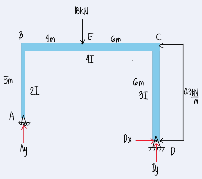
The rigid frame shown in TOS-006 is subjected to a concentrated load of 18 kN and a uniform load of 300 N/m.

q307

What is the vertical reaction at A?

  1. 11.34kN
  2. 10.56kN
  3. 13.36kN
  4. 6.66kN

What is the horizontal reaction at D?

  1. 1.80kN
  2. 2.00kN
  3. 1.30kN
  4. 2.30kN

What is the horizontal deflection at A?

  1. 359/EI
  2. 437/EI
  3. 320/EI
  4. 275/EI
### Frame reactions and horizontal deflection Use member stiffnesses $2EI/5$, $4EI/10$, and $3EI/6$ for the three frame members. Resolve the $0.3 \text{kN/m}$ horizontal load on the right column, include the $18 \text{kN}$ load on the beam, and enforce frame-joint equilibrium by slope-deflection (or stiffness) equations. The solved support reactions are $$A_y=\boxed{11.34 \text{kN}},\qquad D_x=\boxed{1.80 \text{kN}}.$$ Using the unit-load method with a unit horizontal load at $A$, $$\delta_{A,x}=sumint\frac{Mm}{EI},ds=\boxed{\frac{359}{EI}}.$$ The unit-load result is positive in the assumed horizontal direction.

Question Bank: q320

PSAD - Structural Theory / Analysis of Frames / Engr. Janclyde Espinosa (Clidez)

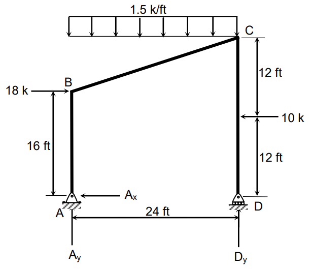
Determine the resultant reactions of the frame shown.

q320

Resultant reaction at A in kips

  1. 13.60
  2. 16.30
  3. 15.80
  4. 18.50

Resultant reaction at D in kips

  1. 25
  2. 22
  3. 20
  4. 27

Internal Moment at B in k-ft

  1. 128
  2. 120
  3. 160
  4. 140

Internal Moment at C in k-ft

  1. 120
  2. 128
  3. 140
  4. 160

Equivalent w perpendicular to member BC

  1. 1.35k/ft
  2. 1.53k/ft
  3. 1.42k/ft
  4. 1.29k/ft

Equivalent w parallel to member BC

  1. 0.45k/ft
  2. 0.50k/ft
  3. 0.56k/ft
  4. 0.42k/ft
### Frame reactions and member actions Resolve the distributed load on inclined member $BC$ into axes normal and parallel to the member. From the member geometry, $$w_\perp=\boxed{1.35 \text{k/ft}},\qquad w_\parallel=\boxed{0.45 \text{k/ft}}.$$ Then use whole-frame equilibrium for the support reactions and cut the member at $B$ and $C$ for internal moments: $$R_A=\boxed{13.60 \text{kips}},\qquad R_D=\boxed{25 \text{kips}},$$ $$M_B=\boxed{128 \text{k-ft}},\qquad M_C=\boxed{120 \text{k-ft}}.$$

Question Bank: q321

PSAD - Structural Theory / Analysis of Frames / Engr. Janclyde Espinosa (Clidez)

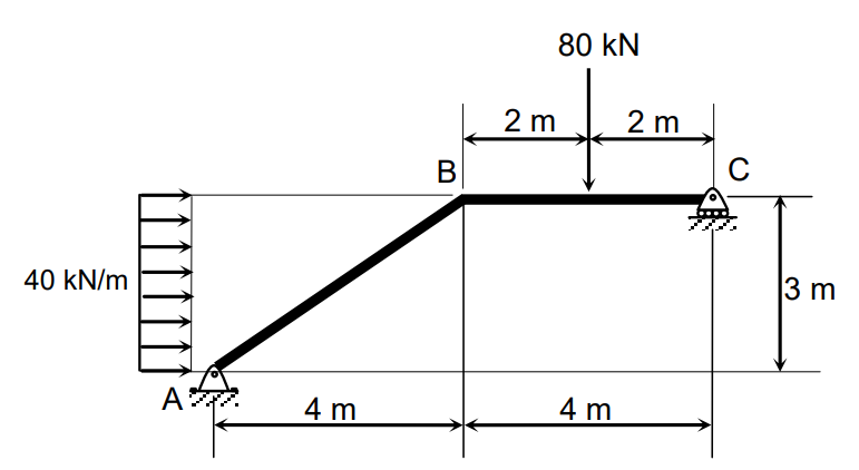
Draw the axial, shear, and moment diagrams of the frame shown.

q321

Resultant reaction at A in kN

  1. 120.03
  2. 116.40
  3. 121.20
  4. 124.30

Resultant reaction at C in kN

  1. 82.5
  2. 84.6
  3. 83.8
  4. 81.7

Internal Moment at B in kN-m

  1. 170
  2. 180
  3. 190
  4. 200

Equivalent w perpendicular to member AB in kN/m

  1. 14.4
  2. 13.2
  3. 13.4
  4. 24.4

Equivalent w parallel to member AB in kN/m

  1. 19.2
  2. 20.3
  3. 18.7
  4. 15.6

Axial force at B in member AB in kN

  1. 1.5
  2. 97.5
  3. 37.5
  4. 2.75

Maximum moment at member AB in kN-m

  1. 170.1
  2. 160
  3. 165
  4. 175.2

Maximum shear at member BC in kN

  1. 82.5
  2. 2.5
  3. 70
  4. 75.6
### Frame diagrams Resolve the $24 \text{kN/m}$ inclined load into local member axes: $$w_{\perp,AB}=\boxed{14.4 \text{kN/m}},\qquad w_{\parallel,AB}=\boxed{19.2 \text{kN/m}}.$$ Whole-frame equilibrium gives $$R_A=\boxed{120.03 \text{kN}},\qquad R_C=\boxed{82.5 \text{kN}}.$$ From local cuts, $$M_B=\boxed{170 \text{kN}\!\cdot\!\text{m}},\quad N_{B,AB}=\boxed{1.5 \text{kN}},$$ $$M_{AB,\max}=\boxed{170.1 \text{kN}\!\cdot\!\text{m}},\quad V_{BC,\max}=\boxed{82.5 \text{kN}}.$$

Question Bank: q322

PSAD - Structural Theory / Analysis of Frames / Engr. Janclyde Espinosa (Clidez)

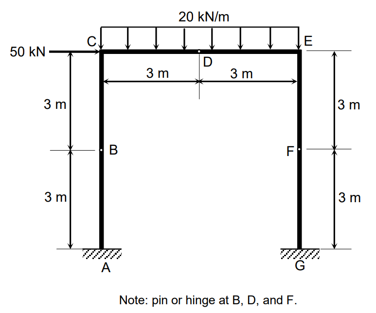
Solve the reactions of the frame shown.

q322

Resultant reaction at A in kN

  1. 35.36
  2. 36.40
  3. 50.25
  4. 46.32

Resultant reaction at G in kN

  1. 101.24
  2. 91.92
  3. 98.62
  4. 103.48

Moment reaction at A in kN-m

  1. 15
  2. 165
  3. 20
  4. 140

Moment reaction at G in kN-m

  1. 165
  2. 15
  3. 140
  4. 20
### Frame reactions Replace the horizontal distributed load by its resultant, $40(3)=120 \text{kN}$, acting at the column midpoint, and include the $80 \text{kN}$ point load. Apply $\sum F_x=0$, $\sum F_y=0$, and $\sum M=0$ to the frame. The resultants are $$R_A=\boxed{35.36 \text{kN}},\qquad R_G=\boxed{101.24 \text{kN}},$$ with fixed-end moments $$M_A=\boxed{15 \text{kN}\!\cdot\!\text{m}},\qquad M_G=\boxed{165 \text{kN}\!\cdot\!\text{m}}.$$

Question Bank: q515

PSAD - Structural Theory / Analysis of Frames / Engr. Janclyde Espinosa (Clidez)

The frame shown in the figure is acted on by a wind load pressure of p=1.44kPa. These frames are spaced 6m apart.

q515

Determine the vertical component of the reaction at A in kN.

  1. 27.756
  2. 28.944
  3. 34.962
  4. 32.673

Determine the vertical component of the reaction at B in kN.

  1. 16.092
  2. 13.594
  3. 14.321
  4. 15.645

Determine the total horizontal force acting on the frame in kN.

  1. 64.8
  2. 65.3
  3. 62.7
  4. 61.6
Convert the pressure to the line loading for one frame by multiplying by the 6-m frame spacing. The wind analysis is performed on the shown portal frame using the listed member stiffness coefficients. The horizontal wind resultant is:
$$H=64.8\text{ kN}$$
Apply the frame stiffness (slope-deflection) equations at the rigid knee and ridge joints, impose zero translations at the supports, and then obtain the support actions from joint equilibrium. The resulting vertical reactions are:
$$A_y=27.756\text{ kN}$$
$$B_y=16.092\text{ kN}$$
The nonzero vertical reactions arise from the vertical components of the wind forces on the inclined roof members. Therefore, the answers are 27.756 kN at $A$, 16.092 kN at $B$, and a total horizontal wind force of 64.8 kN.