CE Board Exam Randomizer

⬅ Back to Subject Topics

Analysis of Beams

Problem: Load and Moment Diagram when Given the Shear Diagram (Overhanging Beam)

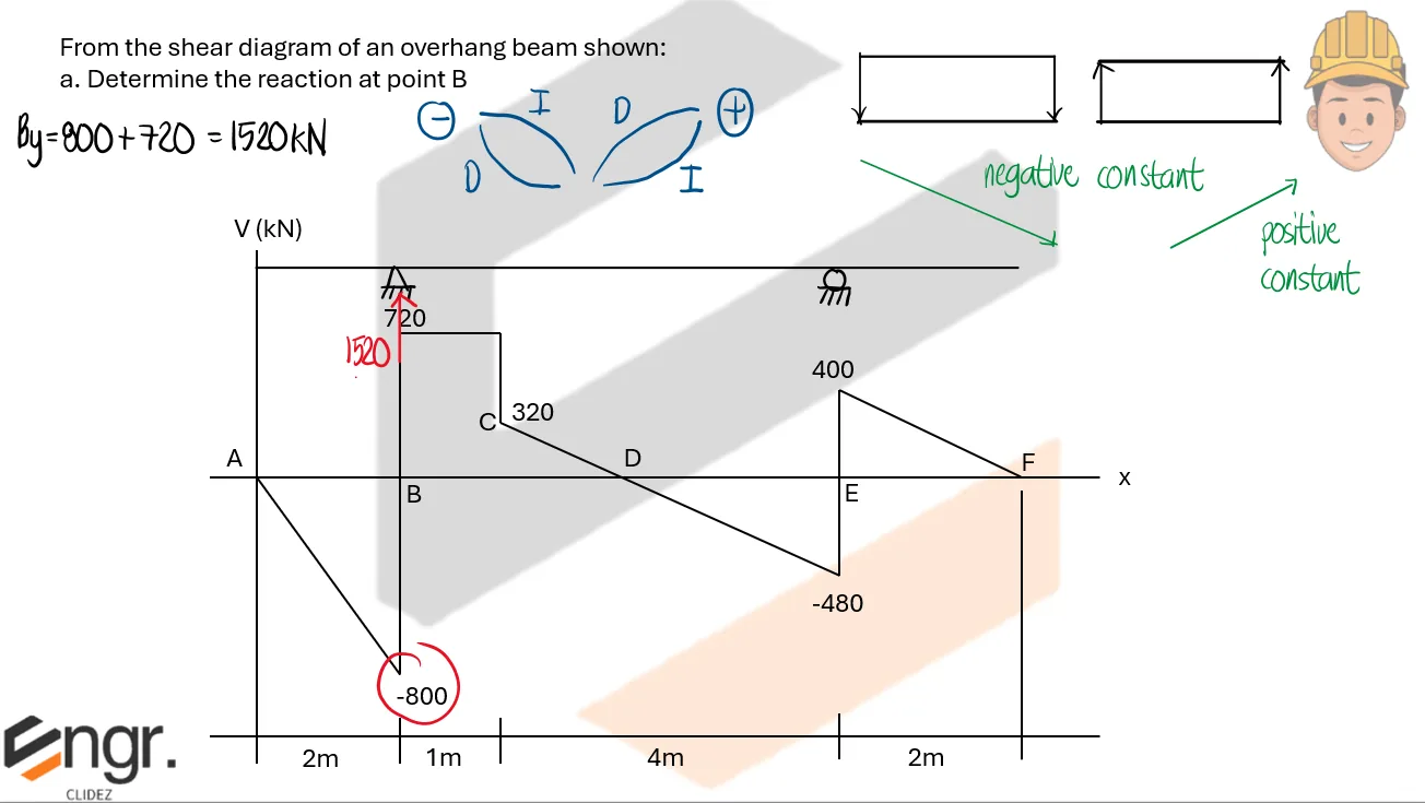
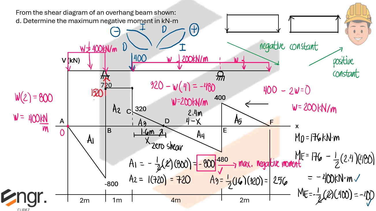
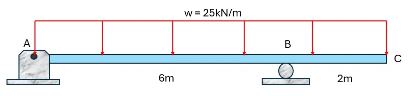
From the shear diagram of an overhang beam shown,
a. Determine the reaction at point B
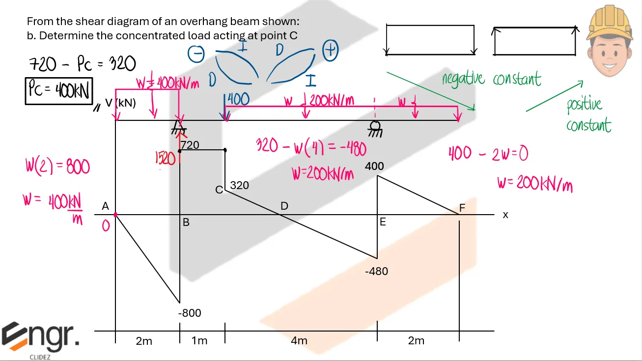
b. Determine the concentrated load at point C
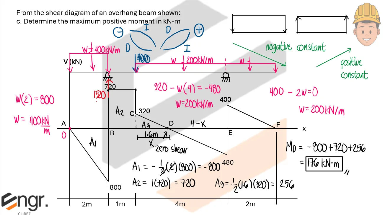
c. Determine the maximum positive moment
d. Determine the maximum negative moment
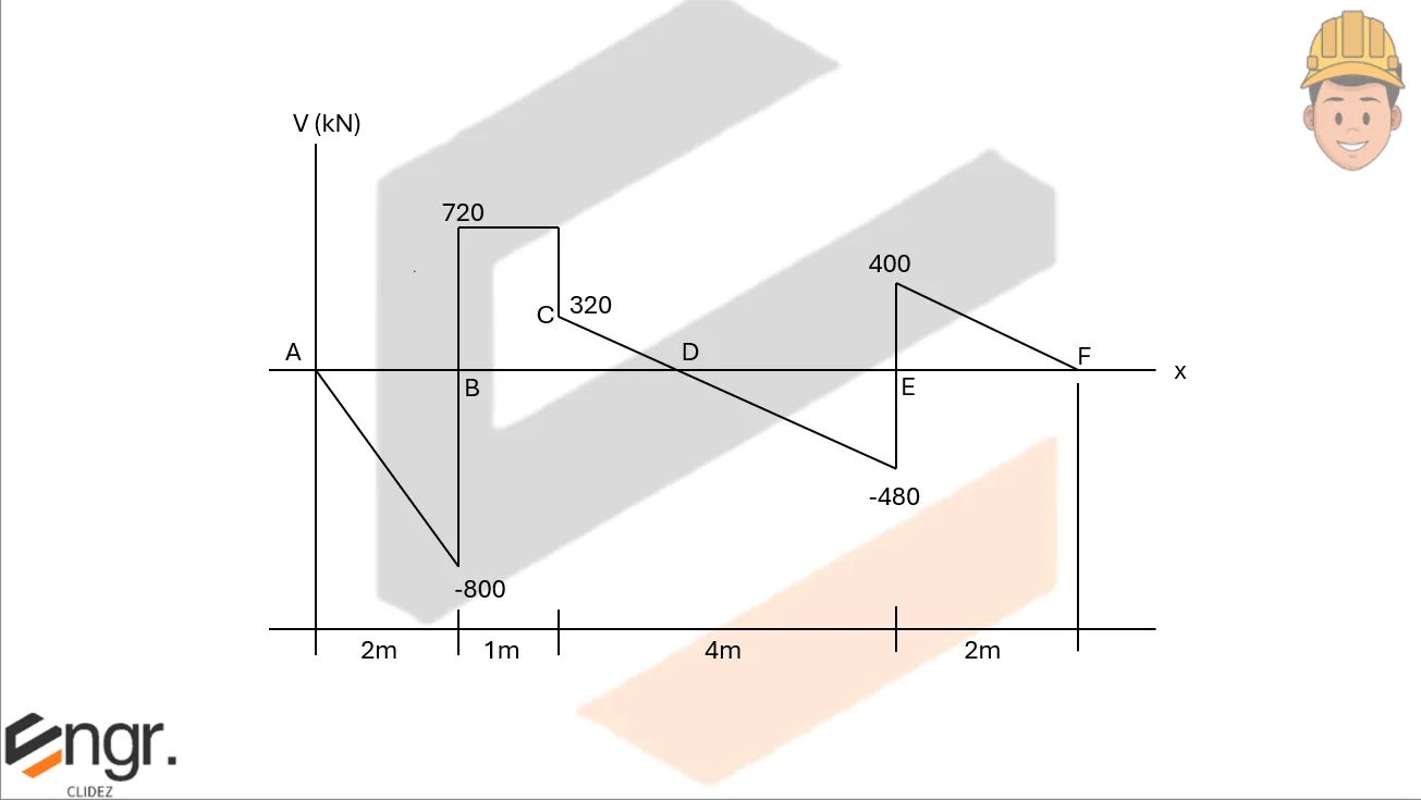
Analysis of Beams | Structural Theory – Problem 1: Load and Moment Diagram when Given the Shear Diagram (Overhanging Beam) – Diagram Analysis of Beams | Structural Theory – Problem 1: Load and Moment Diagram when Given the Shear Diagram (Overhanging Beam) – Diagram Analysis of Beams | Structural Theory – Problem 1: Load and Moment Diagram when Given the Shear Diagram (Overhanging Beam) – Diagram

See images:

Analysis of Beams | Structural Theory – Problem 1: Load and Moment Diagram when Given the Shear Diagram (Overhanging Beam) – Diagram Analysis of Beams | Structural Theory – Problem 1: Load and Moment Diagram when Given the Shear Diagram (Overhanging Beam) – Diagram Analysis of Beams | Structural Theory – Problem 1: Load and Moment Diagram when Given the Shear Diagram (Overhanging Beam) – Diagram Analysis of Beams | Structural Theory – Problem 1: Load and Moment Diagram when Given the Shear Diagram (Overhanging Beam) – Diagram

Problem: Load and Moment Diagram when Given the Shear Diagram (Beam with Couple)

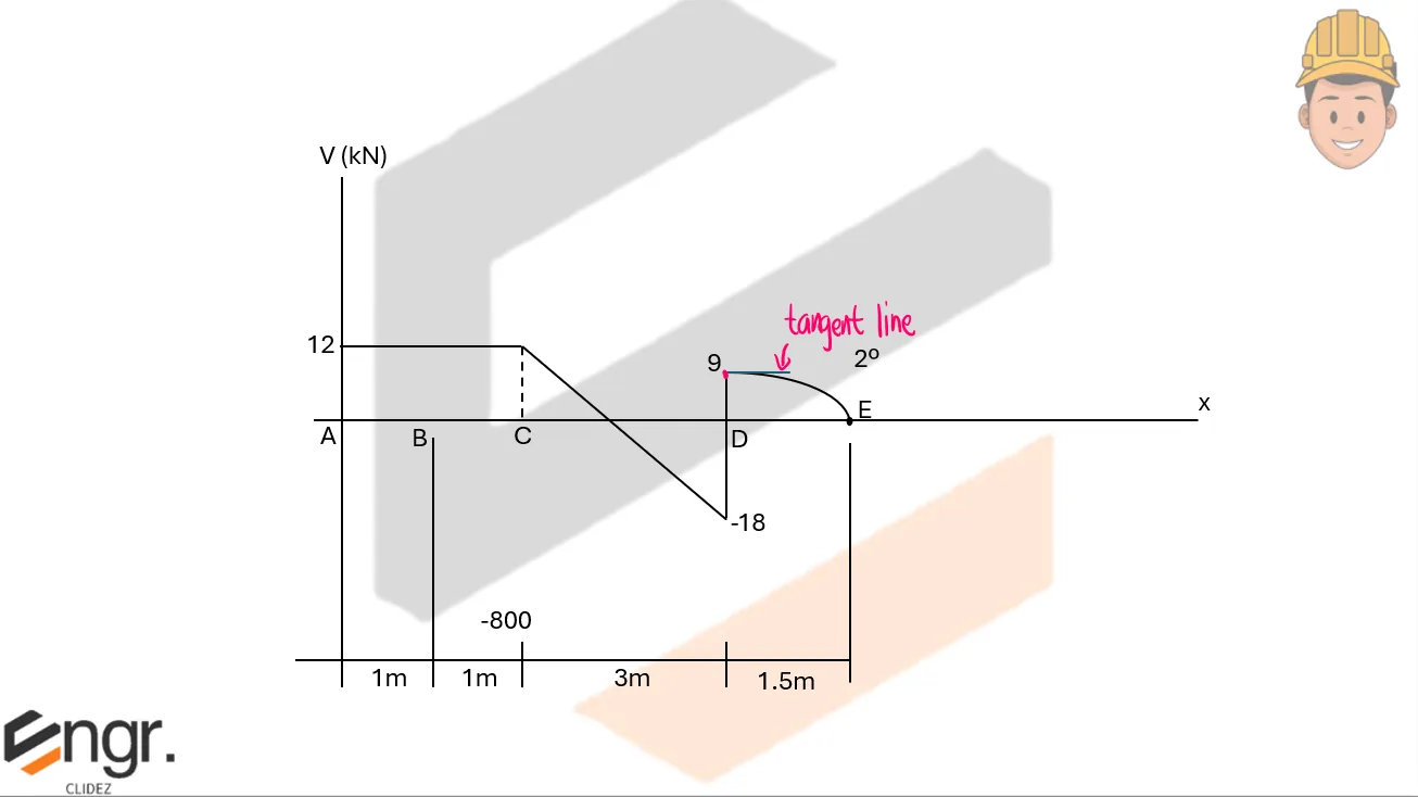
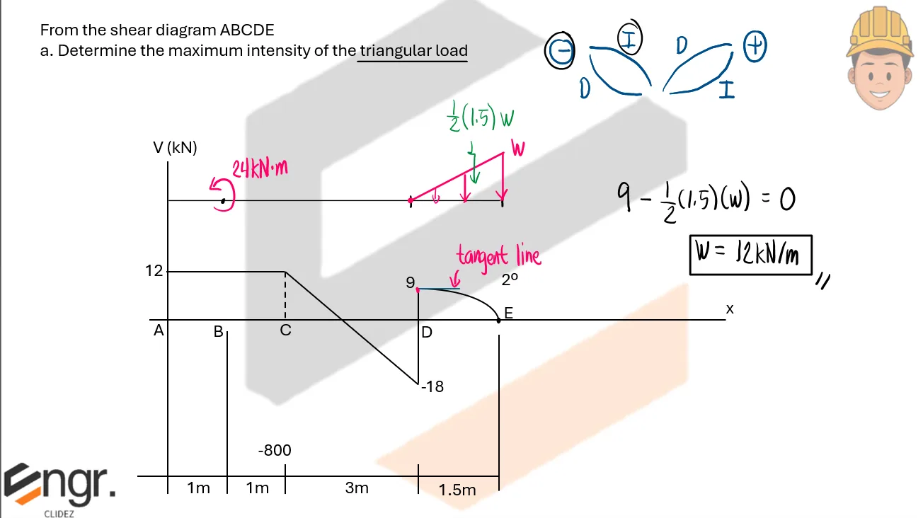
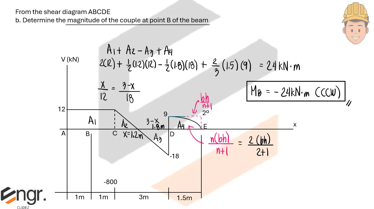
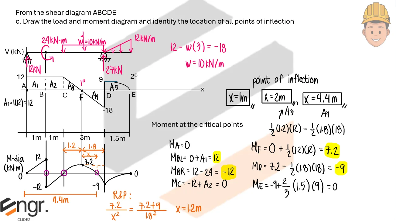
From the shear diagram ABCDE
a. Determine the maximum intensity of the triangular load.
b. Determine the magnitude of the couple at point B of the beam.
c. Draw the load and moment diagram and identify the location of all points of inflection.

Analysis of Beams | Structural Theory – Problem 2: Load and Moment Diagram when Given the Shear Diagram (Beam with Couple) – Diagram Analysis of Beams | Structural Theory – Problem 2: Load and Moment Diagram when Given the Shear Diagram (Beam with Couple) – Diagram Analysis of Beams | Structural Theory – Problem 2: Load and Moment Diagram when Given the Shear Diagram (Beam with Couple) – Diagram

See images:

Analysis of Beams | Structural Theory – Problem 2: Load and Moment Diagram when Given the Shear Diagram (Beam with Couple) – Diagram Analysis of Beams | Structural Theory – Problem 2: Load and Moment Diagram when Given the Shear Diagram (Beam with Couple) – Diagram Analysis of Beams | Structural Theory – Problem 2: Load and Moment Diagram when Given the Shear Diagram (Beam with Couple) – Diagram Analysis of Beams | Structural Theory – Problem 2: Load and Moment Diagram when Given the Shear Diagram (Beam with Couple) – Diagram

Problem: Overhanging Beam with Uniform Load over the whole span

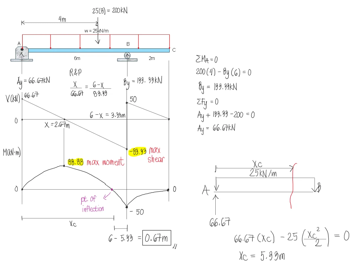
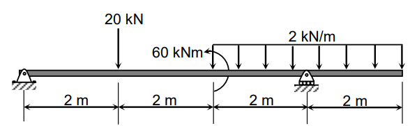
For the beam shown, determine the following:
a. Absolute Maximum Shear
b. Maximum Positive Moment
c. Location of the point of inflection from the right support

Analysis of Beams | Structural Theory – Problem 3: Overhanging Beam with Uniform Load over the whole span – Diagram Analysis of Beams | Structural Theory – Problem 3: Overhanging Beam with Uniform Load over the whole span – Diagram Analysis of Beams | Structural Theory – Problem 3: Overhanging Beam with Uniform Load over the whole span – Diagram

a. 83.33kN
b. 88.88kN-m
c. 0.67m (Note that the question states from the "right" support

Analysis of Beams | Structural Theory – Problem 3: Overhanging Beam with Uniform Load over the whole span – Diagram Analysis of Beams | Structural Theory – Problem 3: Overhanging Beam with Uniform Load over the whole span – Diagram Analysis of Beams | Structural Theory – Problem 3: Overhanging Beam with Uniform Load over the whole span – Diagram Analysis of Beams | Structural Theory – Problem 3: Overhanging Beam with Uniform Load over the whole span – Diagram

Problem: Cantilever beam with triangular load and upward load at the free end

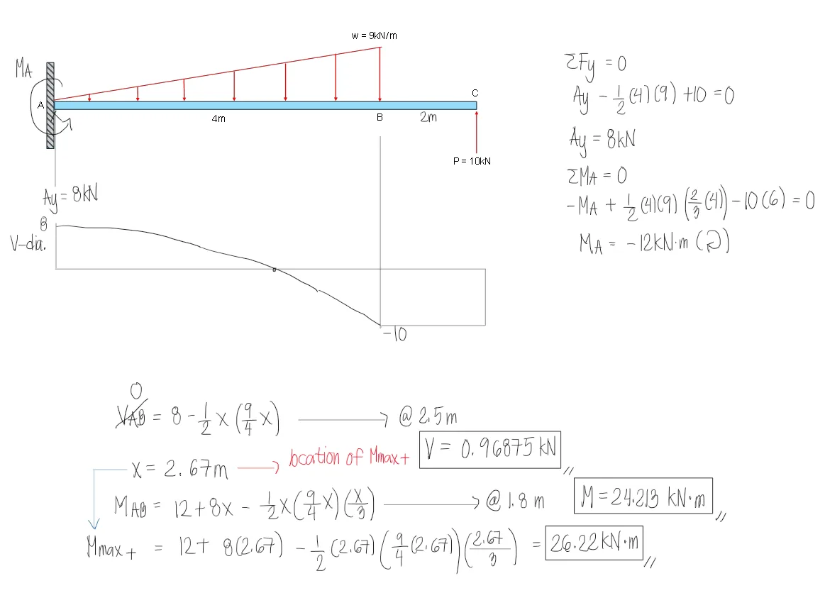
For the beam shown below, determine the following:
a. Maximum moment in kN-m
b. Shear value at 2.5m from the support
c. Moment value at 1.8m from the support

Analysis of Beams | Structural Theory – Problem 4: Cantilever beam with triangular load and upward load at the free end – Diagram Analysis of Beams | Structural Theory – Problem 4: Cantilever beam with triangular load and upward load at the free end – Diagram Analysis of Beams | Structural Theory – Problem 4: Cantilever beam with triangular load and upward load at the free end – Diagram

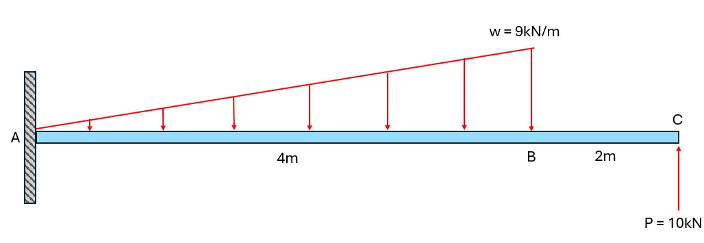
The shear diagram is shown below to demonstrate how tedious the solutions would be if we use the area method. Hence, the shear and moment equation is more ideal for this type of problem where the shear and moment at a point is to be determined.
a. 26.2kN-m
b. 0.96875kN
c. 24.2kN-m

Analysis of Beams | Structural Theory – Problem 4: Cantilever beam with triangular load and upward load at the free end – Diagram Analysis of Beams | Structural Theory – Problem 4: Cantilever beam with triangular load and upward load at the free end – Diagram Analysis of Beams | Structural Theory – Problem 4: Cantilever beam with triangular load and upward load at the free end – Diagram Analysis of Beams | Structural Theory – Problem 4: Cantilever beam with triangular load and upward load at the free end – Diagram

Problem:

Refer to the image shown:

Analysis of Beams | Structural Theory – Problem 5: – Diagram Analysis of Beams | Structural Theory – Problem 5: – Diagram Analysis of Beams | Structural Theory – Problem 5: – Diagram

See images:

Analysis of Beams | Structural Theory – Problem 5: – Diagram Analysis of Beams | Structural Theory – Problem 5: – Diagram Analysis of Beams | Structural Theory – Problem 5: – Diagram Analysis of Beams | Structural Theory – Problem 5: – Diagram

Problem:

Refer to the image shown:

Analysis of Beams | Structural Theory – Problem 6: – Diagram Analysis of Beams | Structural Theory – Problem 6: – Diagram Analysis of Beams | Structural Theory – Problem 6: – Diagram

See images:

Analysis of Beams | Structural Theory – Problem 6: – Diagram Analysis of Beams | Structural Theory – Problem 6: – Diagram Analysis of Beams | Structural Theory – Problem 6: – Diagram Analysis of Beams | Structural Theory – Problem 6: – Diagram

Problem:

Refer to the image shown:

Analysis of Beams | Structural Theory – Problem 7: – Diagram Analysis of Beams | Structural Theory – Problem 7: – Diagram Analysis of Beams | Structural Theory – Problem 7: – Diagram

See images:

Analysis of Beams | Structural Theory – Problem 7: – Diagram Analysis of Beams | Structural Theory – Problem 7: – Diagram Analysis of Beams | Structural Theory – Problem 7: – Diagram Analysis of Beams | Structural Theory – Problem 7: – Diagram

Problem:

Refer to the image shown:

Analysis of Beams | Structural Theory – Problem 8: – Diagram Analysis of Beams | Structural Theory – Problem 8: – Diagram Analysis of Beams | Structural Theory – Problem 8: – Diagram

See images:

Analysis of Beams | Structural Theory – Problem 8: – Diagram Analysis of Beams | Structural Theory – Problem 8: – Diagram Analysis of Beams | Structural Theory – Problem 8: – Diagram Analysis of Beams | Structural Theory – Problem 8: – Diagram
-->
Scroll to zoom

Exam Generator Problems

Additional board-style practice items for this topic.

Question Bank: q315

PSAD - Structural Theory / Shear and Moment in Beams / Engr. Janclyde Espinosa (Clidez)

Draw the shear and moment diagram of the beam shown.

q315

Determine the reaction at A.

  1. 23.33
  2. 4.67
  3. 43.33
  4. 24.67

Determine the absolute maximum shear.

  1. 23.33
  2. 4.67
  3. 24.67
  4. 43.33

Determine the maximum positive moment.

  1. 53.32
  2. 46.66
  3. 52.33
  4. 48.67

Determine the maximum negative moment.

  1. 6.66
  2. 3.91
  3. 4.00
  4. 6.92

Solution pending in psadquestions/q315.json.

Question Bank: q553

PSAD - Structural Theory / Combined Topics in Structural Theory and Strength of Materials / Engr. Deguma

For the beam shown, if w=30kN/m and L=6m:

q553

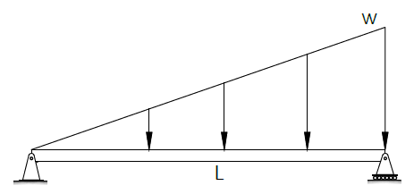
Determine the location of the maximum moment from the left support in meters.

  1. 3.46m
  2. 2.67m
  3. 3.33m
  4. 2.54m

If the beam has dimensions, 50 mm width and 150 mm depth, compute the maximum bending stress of the beam.

  1. 370
  2. 360
  3. 340
  4. 320

If EI is constant, which if the following most nearly gives the maximum deflection of the beam.

  1. 253.50/EI
  2. 265.50/EI
  3. 290.10/EI
  4. 275.20/EI

Part 1.

For a simply supported beam with triangular load increasing from zero at the left to $w$ at the right, the shear is zero at:
$x=\frac{L}{\sqrt{3}}$
With $L=6$ m:
$x=\frac{6}{\sqrt{3}}=3.46\text{ m}$
$\boxed{x=3.46\text{ m from the left support}}$

Part 2.

The maximum moment for this triangular load case is:
$M_{max}=\frac{wL^2}{9\sqrt{3}}$
$M_{max}=\frac{30(6^2)}{9\sqrt{3}}=69.28\text{ kN-m}$
For the rectangular section, $I=\frac{bd^3}{12}=\frac{50(150^3)}{12}=14.0625\times10^6\text{ mm}^4$ and $c=75$ mm.
$f_b=\frac{Mc}{I}=\frac{69.28\times10^6(75)}{14.0625\times10^6}$
$\boxed{f_b\approx370\text{ MPa}}$

Part 3.

For a simply supported beam with triangular load increasing to $w$ at the right, the maximum deflection coefficient is:
$\Delta_{max}=0.006522\frac{wL^4}{EI}$
$\Delta_{max}=0.006522\frac{30(6^4)}{EI}$
$\boxed{\Delta_{max}=\frac{253.50}{EI}}$

Question Bank: q601

PSAD - Structural Theory / Combined Topics in Structural Theory and Strength of Materials / Mastermatician

A 6-m long simply supported timber beam is subjected to a uniform load of 20 kN/m. Given: b = 200 mm, h = 500 mm, E = 8.33 GPa, Specific Gravity = 0.72.

Calculate the maximum moment, in kN-m.

  1. 93.18
  2. 86.82
  3. 94.41
  4. 90.00

What is the maximum flexural stress developed in the beam, in MPa?

  1. 11.18
  2. 10.80
  3. 11.33
  4. 10.42

Calculate the maximum deflection of the beam, in mm.

  1. 20.13
  2. 20.40
  3. 19.45
  4. 18.76

If the uniform load is to be replaced by a concentrated load acting at the midspan such that the deflection of the beam produced by the loads are equal, find the magnitude of the concentrated load, in kN.

  1. 75.00
  2. 78.68
  3. 77.65
  4. 72.35

Solution pending in psadquestions/q601.json.

Question Bank: q619

PSAD - Structural Theory / Combined Topics in Structural Theory and Strength of Materials / Mastermatician

A 6m long beam is supported by a roller at the right end and a fixed support at the left end. It carries a uniform load of ‘w’ kN/m throughout the beam.

Compute the safe value of ‘w’ so that it will not exceed the flexural capacity of the beam of 270 kN-m, in kN/m.

  1. 60
  2. 90
  3. 180
  4. 30

Compute the safe value of ‘w’ so that it will not exceed the shear capacity of the beam of 180 kN, in kN/m.

  1. 48
  2. 80
  3. 72
  4. 64

Compute the safe value of ‘w’ so that it will not exceed the deflection of 30 mm at the right end when the roller support is removed. Flexural rigidity of the beam is 432x1012 N-mm2, in kN/m.

  1. 80
  2. 70
  3. 90
  4. 100

Solution pending in psadquestions/q619.json.

Question Bank: q620

PSAD - Structural Theory / Combined Topics in Structural Theory and Strength of Materials / Mastermatician

A cantilever beam 4 m long deflects by 16 mm at its free end due to a uniformly distributed load of 25 kN/m throughout its length.

To prevent beam deflection at the free end, what force P (kN) is needed at that point?

  1. 37.5
  2. 18.8
  3. 75.0
  4. 56.3

What force P (kN) should be applied at the mid length of the beam for zero displacement at the free end?

  1. 120.0
  2. 51.2
  3. 60.0
  4. 37.5

To reduce the deflection at the free end to 10 mm, how much force is needed to be applied at that point?

  1. 14.1
  2. 23.4
  3. 10.5
  4. 28.1

Solution pending in psadquestions/q620.json.