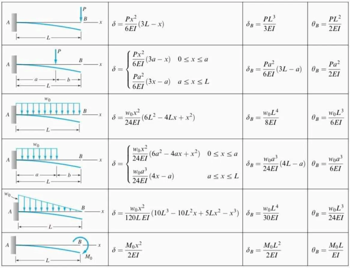
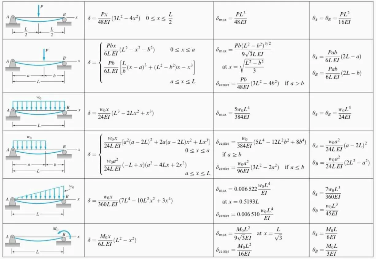
The Superposition Theorem states that the total moment or deflection in a linear structure under multiple loads can be found by summing the effects of individual loads applied separately. This is valid as long as the structure behaves elastically --> follows Hooke's Law. Below is a complete list of the formulas we can use for any beam, but we will later discuss how we only need to memorize at least five formulas in total if we combine the concept of integration in formulas with point loads.
Image excerpted from Pytel, F., & Kiusalaas, J. (2012). Engineering Mechanics: Statics and Dynamics 4th ed. Cengage Learning. Used under fair use for educational and illustrative purposes.
Problem: Cantilever Beam with Uniform Load and Concentrated Load at the Free End
A 4-m long cantilever beam carries a concentrated load of 50kN at the free end and a uniformly distributed load of 20kN/m throughout the entire span. The beam is made of steel where E=200GPa and I=200x106mm4
See images:
Problem: Cantilever Beam Resting on a Simply Supported Beam | Consistent Deformation with Superposition
Beam BD is fixed at D and is supported by girder AC at B with P=14kN applied at the free end.
L1=4m, L2=2m, L3=4m.
The Section Modulus of both members about the plane of bending is:
S=6.18x105mm3
See images:
Problem: Application of Formulas for Fixed-Ended Beam
Refer to the load diagrams shown:
a. If MA = -10 kN-m, L = 6 m, calculate P in kN based on Figure A. a. 7.5
b. 10
c. 5
d. 12.5
b. If MA = -40 kN-m, L = 10 m, calculate w in kN/m based on Figure B.
a. 6.78
b. 8.76
c. 8.67 d. 7.68
c. If MA = -60 kN-m, MB = -90 kN-m, L = 10 m, calculate w in kN/m based on Figure C.
a. 15 b. 18
c. 21
d. 24
See images:
Problem: Cantilever Beam with Uniform Load Resting on a Simply Supported Beam | Consistent Deformation
Refer to the figure shown. A cantilever beam rests on B of beam ABC. THe cantilever beam carries a uniform load W=24.6kN/m throughout its length. Prior to loading, the cantilever beam is only touching beam ABC at B. Both beams have identical cross-sectional properties. Given the following data:
L1=4m
L2=2m
E=30GPa
I=1333x106mm4
See images:
Problem: Force to Apply at Mid-Length to Eliminate Deflection at Free-End
A 5-meter cantilever beam, 300mm x 400mm in cross-section carries a total uniformly distributed load of 5.20kN/m. E=25GPa. What force (in kN) should be applied at the mid-length of the beam to eliminate the deflection at the free end?
Additional board-style practice items for this topic.
Question Bank: q21
PSAD - Structural Theory / Slope and Deflection / Engr. Janclyde Espinosa (Clidez)
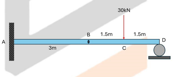
For the beam shown, E=200GPa and I=19,430,000mm4 Note: Point B has an internal hinge.
Determine the deflection at B in mm.
37.74
32.65
33.67
39.82
Determine the left and right slope values at B in radians.
-0.01737, 0.0072375
-0.01373, 0.0075372
-0.01773, 0.0077325
-0.013377, 0.0073325
Determine the deflection at C in mm.
21.713
23.714
25.628
26.825
The internal hinge at B has zero bending moment. Analyze span BD as a simply supported span, then apply its hinge shear to cantilever AB. Integrate $EIy''=M$ for each segment and enforce zero deflection at A and D plus equal vertical deflection at B.
Part 1. The compatibility solution gives $v_B=\boxed{37.74\text{ mm downward}}$.
Part 2. The rotations on the two sides of the hinge are independent: $\theta_{B,\left}=\boxed{-0.01737\text{ rad}}$ and $\theta_{B,\right}=\boxed{0.0072375\text{ rad}}$.
Part 3. Substitution of the integration constants at C gives $v_C=\boxed{21.713\text{ mm downward}}$.
Question Bank: q28
PSAD - Structural Theory / Slope and Deflection / Engr. Janclyde Espinosa (Clidez)
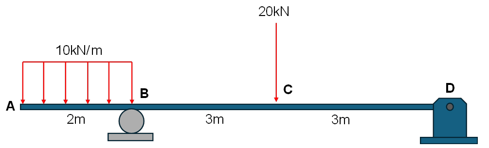
For the beam shown, use E=100GPa and I=10x10⁷mm⁴.
Determine the deflection at A in mm.
1
2.4
2.8
1.6
Determine the deflection at C in mm.
4.5
6.3
5.2
3.7
Take B and D as the supports. From statics, $R_B+R_D=10(2)+20=40\text{ kN}$ and $\sum M_B=0$, which gives $R_B=33.333\text{ kN}$ and $R_D=6.667\text{ kN}$. Use the bending-moment functions on AB, BC, and CD and integrate $EIy''=M$.
Apply $v_B=v_D=0$ and continuity of deflection and slope at C.
Part 1. $v_A=\boxed{1.0\text{ mm}}$.
Part 2. $v_C=\boxed{4.5\text{ mm}}$.
The reported values are downward deflections.
Question Bank: q144
PSAD - Structural Theory / Slope and Deflection / Engr. Janclyde Espinosa (Clidez)
A 12m simple beam is loaded with a uniform load w = 40kN/m over the entire span and a concentrated load P = 200kN at the midspan. EI is constant.
Which of the following most nearly gives the slope at the support due to the concentrated load only?
1800/EI
4800/EI
7200/EI
3600/EI
Which of the following most nearly gives the maximum slope due to the uniform load only?
2880/EI
9600/EI
6400/EI
10800/EI
Which of the following most nearly gives the maximum deflection due to the given loads?
18000/EI
14400/EI
10000/EI
10800/EI
### Slope and deflection by superposition
For a simply supported beam of span $L=12 \text{m}$:
$$\theta_{\text{support},P}=\frac{PL^2}{16EI},\qquad \theta_{\text{support},w}=\frac{wL^3}{24EI},$$
and the midspan deflections are
$$\delta_{\max,P}=\frac{PL^3}{48EI},\qquad \delta_{\max,w}=\frac{5wL^4}{384EI}.$$
For the centered point load,
$$\theta_{\text{support},P}=\frac{200(12)^2}{16EI}=\boxed{\frac{1800}{EI}}.$$
For the UDL, the maximum slope occurs at either support:
$$\theta_{\max,w}=\frac{40(12)^3}{24EI}=\boxed{\frac{2880}{EI}}.$$
Both loads cause their maximum deflection at midspan, so superposition gives
$$\delta_{\max}=\frac{200(12)^3}{48EI}+\frac{5(40)(12)^4}{384EI}$$
$$=\frac{7200+10800}{EI}=\boxed{\frac{18000}{EI}}.$$
The original third key, $4680/EI$, does not follow from the stated loads and has been corrected.
Question Bank: q152
PSAD - Structural Theory / Slope and Deflection / Engr. Janclyde Espinosa (Clidez)
A 12 m-simply supported beam is loaded
with a concentrated load P = 12 kN at 3 meters from the right support. E = 200
GPa and I = 60 000 000 mm4
Compute the rotation at the left support in radians.
0.005625
0.00673
0.00265
0.00375
Compute the rotation at the right support in radians.
0.00788
0.00375
0.00265
0.00525
Part 1.
$L=12$ m; $P=12$ kN at $a=9$ m from left ($b=3$ m from right) $EI = 200{,}000 \text{ MPa} \times 60{\times}10^6 \text{ mm}^4 = 12{\times}10^{12} \text{ N·mm}^2 = 12{,}000 \text{ kN·m}^2$ $\theta_A = \frac{Pb(L^2-b^2)}{6EIL} = \frac{12 \times 3 \times (144-9)}{6 \times 12{,}000 \times 12}$ $= \frac{12 \times 3 \times 135}{864{,}000} = \frac{4{,}860}{864{,}000}$ $\boxed{= 0.005625 \text{ rad}}$
A beam having a span of 6 meters is supported at the left end by a spring which has a spring constant of 50
kN/m. E = 10000 MPa and I = 60x 106 mm4.
Which of the following nearly gives the
reaction at point A in Newtons?
1157
1258
1125
1185
Which of the following nearly gives the
moment at the fixed support in Newton-meter?
-3858
-4050
-3252
-3690
Which of the following nearly gives the
deflection of the spring in mm.
23.14
23.70
25.16
22.50
Cantilever Beam with Trapezoidal Load
PSAD - Structural Theory / Slope and Deflection / Engr. Janclyde Espinosa (Clidez)
For the beam shown, assume EI is constant.
Determine the slope at the free end.
288/EI
144/EI
264/EI
132/EI
Determine the deflection at the free end.
1274.4/EI
1374.6/EI
1349.2/EI
1138.8/EI
Determine the slope at the midspan.
247.5/EI
240.6/EI
270.9/EI
250.5/EI
Determine the deflection at the midspan.
441.45/EI
508.95/EI
430/EI
540/EI
Question Bank: q310
PSAD - Structural Theory / Slope and Deflection / Engr. Janclyde Espinosa (Clidez)
For the beam shown, assume EI is constant.
Determine the slope at the free end.
1800/EI
1600/EI
1700/EI
1500/EI
Determine the deflection at the free end.
7200/EI
3600/EI
6800/EI
3400/EI
Determine the slope at the midspan.
1350/EI
1250/EI
1400/EI
1375/EI
Determine the deflection at the midspan.
2250/EI
2500/EI
2480/EI
2360/EI
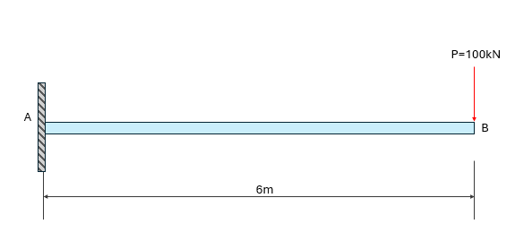
### Cantilever with end load
For $P=100 \text{kN}$ and $L=6 \text{m}$,
$$\theta_B=\frac{PL^2}{2EI}=\boxed{\frac{1800}{EI}},\qquad y_B=\frac{PL^3}{3EI}=\boxed{\frac{7200}{EI}}.$$
At $x=3 \text{m}$ from the fixed end,
$$\theta_x=\frac{Px(2L-x)}{2EI}=\boxed{\frac{1350}{EI}},$$
$$y_x=\frac{Px^2(3L-x)}{6EI}=\boxed{\frac{2250}{EI}}.$$
Question Bank: q311
PSAD - Structural Theory / Slope and Deflection / Engr. Janclyde Espinosa (Clidez)
For the beam shown, assume EI is constant.
Determine the deflection at the midspan.
4258.8/EI
4285.8/EI
4288.5/EI
4528.8/EI
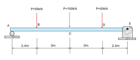
### Deflection at the middle load
Determine the two support reactions from global equilibrium, write the piecewise bending-moment functions between the three point loads, and integrate $EIy''=M(x)$. Apply zero deflection at the two supports and continuity of slope and deflection at the load points. At midspan $C$, the result is
$$\boxed{y_C=\frac{4258.8}{EI}}.$$
The direction is downward under the loading.
Question Bank: q312
PSAD - Structural Theory / Slope and Deflection / Engr. Janclyde Espinosa (Clidez)
For the beam shown, assume EI is constant.
Determine the deflection at 5.5m from the left support.
964.4625/EI
835.3125/EI
129.15/EI
1093.6125/EI
Determine the deflection at point C.
834.6/EI
735/EI
99.6/EI
934.2/EI
Determine the slope at D.
334.3/EI
297.5/EI
36.8/EI
371.1/EI
Determine the deflection at E.
802.32/EI
807.5/EI
714/EI
890.64/EI
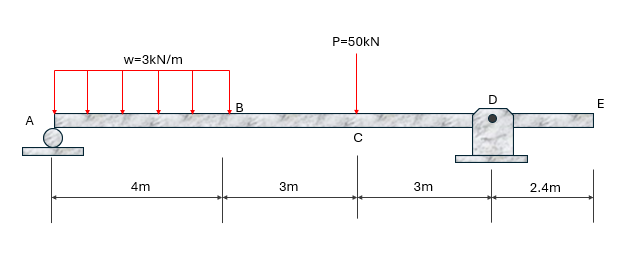
### Beam deflections and slope
Obtain the reactions from the three point loads, then use the moment-area relations
$$\theta_{PQ}=\int_P^Q\frac{M}{EI},dx,$$
$$t_{Q/P}=\int_P^Q\frac{Mx_Q}{EI},dx.$$
Applying the support-deflection conditions produces
$$y_{x=5.5}=\boxed{\frac{964.4625}{EI}},\qquad y_C=\boxed{\frac{834.6}{EI}},$$
$$\theta_D=\boxed{\frac{334.3}{EI}},\qquad y_E=\boxed{\frac{802.32}{EI}}.$$
Overhanging Beam with Uniform Load at Simple Span and Concentrated Load at Free End
PSAD - Structural Theory / Slope and Deflection / Engr. Janclyde Espinosa (Clidez)
Determine the deflection at the free end using Superposition Method.
Determine the deflection at C caused by the concentrated load alone. Remove the uniformly distributed load.
466.66/EI
333.33/EI
133.33/EI
366.66/EI
Determine the slope at B caused by the uniformly distributed load.
208.33/EI
133.33/EI
236.66/EI
254.58/EI
Determine the deflection at C
50/EI (downward)
50/EI (upward)
60/EI (upward)
60/EI (downward)
Question Bank: q544
PSAD - Structural Theory / Slope and Deflection / Engr. Deguma
A 6-meter-cantilever-beam (fixed at left) is loaded with 3 concentrated loads
P1, P2 and P3 applied at 2 m, 4 m, and 6 m from the fixed support,
respectively. If P1 = P2 = P3 = 30 kN and EI is constant, compute the
following:
The moment at 1m from the fixed support in kN-m.
270
180
210
360
The slope at the free end.
840/EI
480/EI
720/EI
540/EI
The deflection at the free end.
3600/E I
2400/EI
1800/EI
4800/EI
At the section $1\text{ m}$ from the fixed end, all three $30\text{-kN}$ loads lie to the right. Their moment about the section is: $$M=30[(2-1)+(4-1)+(6-1)]=270\text{ kN}\cdot\text{m}$$ The free-end slope due to a point load $P$ at distance $a$ from the fixed end is $Pa^2/(2EI)$. Therefore: $$\theta_{free}=\frac{30(2)^2}{2EI}+\frac{30(4)^2}{2EI}+\frac{30(6)^2}{2EI}=\frac{840}{EI}$$ The free-end deflection due to a load at $a$ is $Pa^2(3L-a)/(6EI)$, with $L=6\text{ m}$: $$\delta_{free}=\sum\frac{30a^2(18-a)}{6EI}=\frac{3600}{EI}$$
Therefore, the answers are 270 kN·m, $840/EI$, and $3600/EI$.
Timber Beam with Self-Weight
PSAD - Structural Theory / Combined Topics in Structural Theory and Strength of Materials / Mastermatician
A 6-m long simply supported timber beam is
subjected to a uniform load of 20 kN/m. Given: b = 200 mm,
h = 500 mm, E = 8.33 GPa, Specific Gravity = 0.72.
Calculate the maximum moment, in kN-m.
93.18
86.82
94.41
90.00
What is the maximum flexural stress developed in the beam,
in MPa?
11.18
10.80
11.33
10.42
Calculate the maximum deflection of the beam, in mm.
20.13
20.40
19.45
18.76
If the uniform load is to be replaced by a concentrated load
acting at the midspan such that the deflection of the beam
produced by the loads are equal, find the magnitude of the
concentrated load, in kN.