CE Board Exam Randomizer

⬅ Back to Subject Topics

Frames

Concept Concept

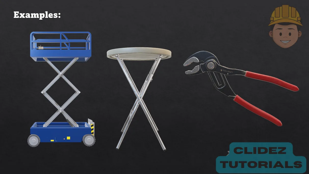
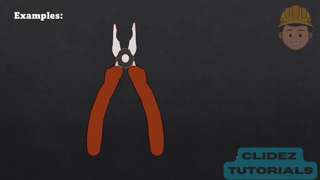
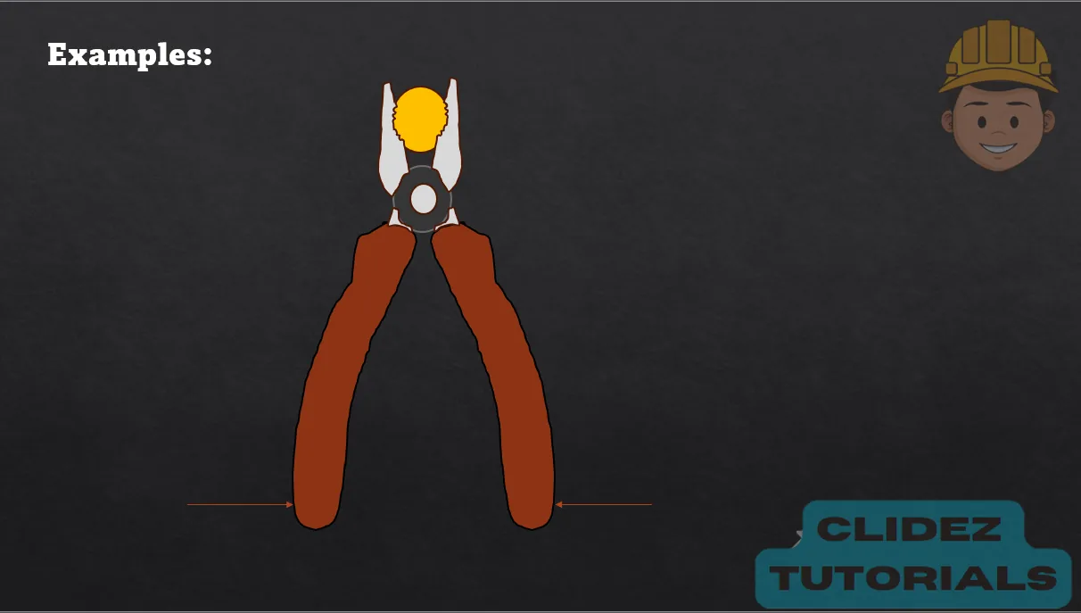
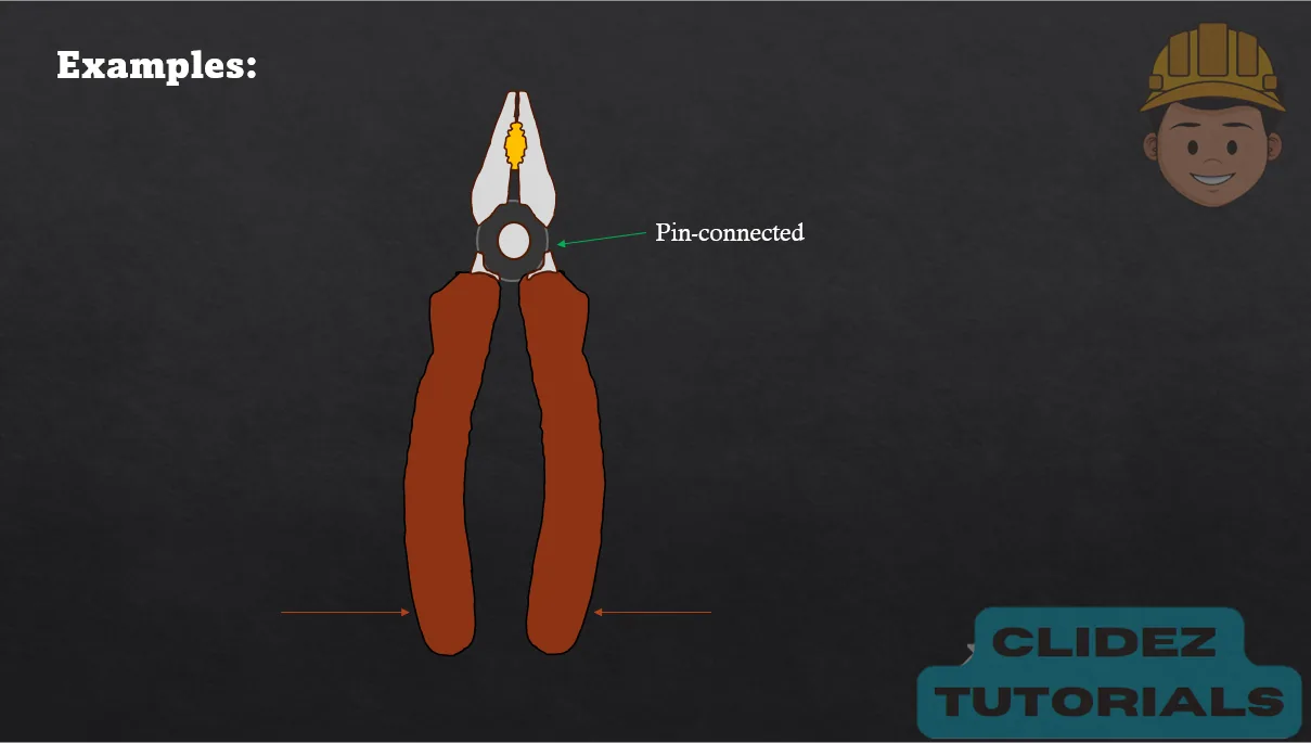
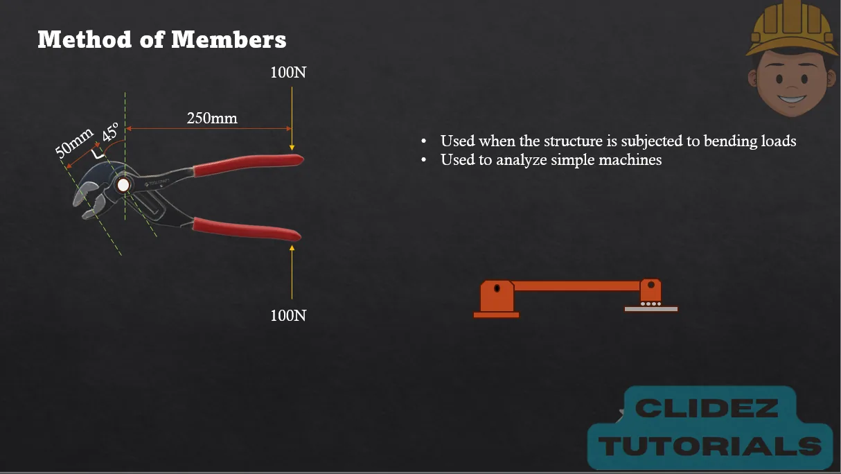
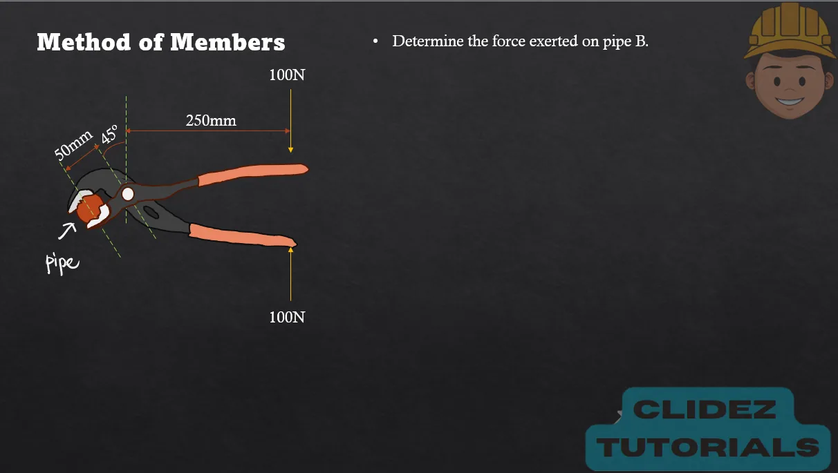
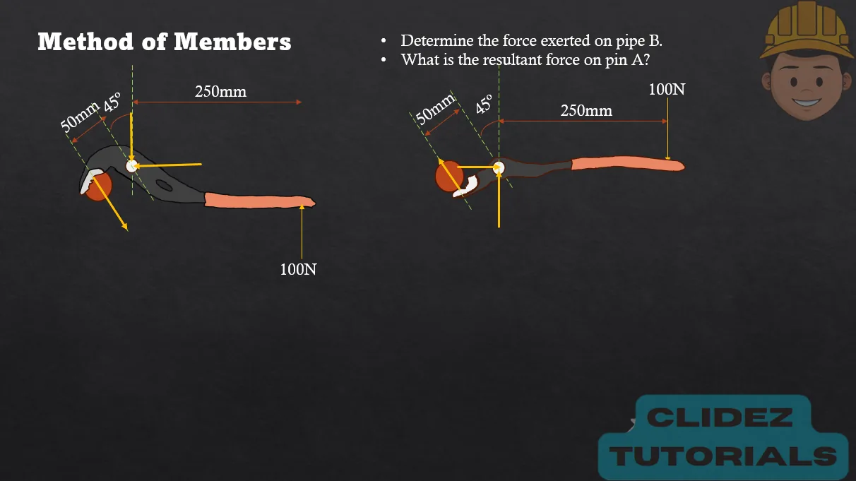
Frames and machines like pliers and wrenches use pin connections to create mechanical advantage—they allow a small applied force at one point to produce a much larger force at another. This is especially helpful when we need to exert forces that would be difficult or impossible with our bare hands, such as tightening bolts or gripping pipes. The pin joints act as pivots, allowing different members of the frame to rotate and transfer forces efficiently.

As in the case of the pliers, the input force (from our hand) travels through rigid links and pivots, generating a greater output force at the jaws due to the geometry and relative lengths of the members—shorter output arms and longer input arms multiply the applied force.

This principle is the same behind levers and is fundamental to machines like wrenches, clamps, scissors, and even robotic arms.

Concept Concept Concept Concept Concept Concept Concept Concept Concept Concept Concept

Problem: Frame with Pulley by Method of Members

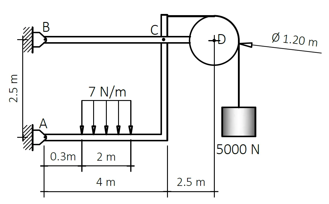
For the frame shown, the pulley has a mass of 200kg and is frictionless. Neglect the weight of the bars and determine the following:
a. Determine the resultant reaction at D. (8571.432N)
b. Determine the resultant reaction at C. (26812.158N)
c. Determine the resultant reaction at A. (22385.8N)
d. Determine the resultant reaction at B. (19792.695N)

Analysis of Pin-connected Frames | Statics of Rigid Bodies – Problem 1: – Diagram Analysis of Pin-connected Frames | Statics of Rigid Bodies – Problem 1: – Diagram Analysis of Pin-connected Frames | Statics of Rigid Bodies – Problem 1: – Diagram

See images:

Analysis of Pin-connected Frames | Statics of Rigid Bodies – Problem 1: – Diagram Analysis of Pin-connected Frames | Statics of Rigid Bodies – Problem 1: – Diagram Analysis of Pin-connected Frames | Statics of Rigid Bodies – Problem 1: – Diagram Analysis of Pin-connected Frames | Statics of Rigid Bodies – Problem 1: – Diagram

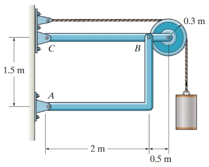
Problem: Frame with Pulley

Determine the resultant reaction at A if the mass of the block is 75kg. (1532.8N)

Analysis of Pin-connected Frames | Statics of Rigid Bodies – Problem 2: – Diagram Analysis of Pin-connected Frames | Statics of Rigid Bodies – Problem 2: – Diagram Analysis of Pin-connected Frames | Statics of Rigid Bodies – Problem 2: – Diagram

See images:

Analysis of Pin-connected Frames | Statics of Rigid Bodies – Problem 2: – Diagram Analysis of Pin-connected Frames | Statics of Rigid Bodies – Problem 2: – Diagram Analysis of Pin-connected Frames | Statics of Rigid Bodies – Problem 2: – Diagram Analysis of Pin-connected Frames | Statics of Rigid Bodies – Problem 2: – Diagram

Problem: Frame with Internal Hinge | CE Past Board Exam

The frame shown in the figure is acted on by wind load pressure of p=1.44kPa. These frames are spaced 6m apart.
a. Determine the vertical component of the reaction at A. (27.756kN)
b. Determine the vertical component of the reaction at B. (16.092kN)
c. Determine the total horizontal force acting on the frame. (64.8kN)

Analysis of Pin-connected Frames | Statics of Rigid Bodies – Problem 3: – Diagram Analysis of Pin-connected Frames | Statics of Rigid Bodies – Problem 3: – Diagram Analysis of Pin-connected Frames | Statics of Rigid Bodies – Problem 3: – Diagram

See images:

Analysis of Pin-connected Frames | Statics of Rigid Bodies – Problem 3: – Diagram Analysis of Pin-connected Frames | Statics of Rigid Bodies – Problem 3: – Diagram Analysis of Pin-connected Frames | Statics of Rigid Bodies – Problem 3: – Diagram Analysis of Pin-connected Frames | Statics of Rigid Bodies – Problem 3: – Diagram

Problem: Beam with Internal Hinge by Method of Members

For the continuous beam shown, P=356kN and w=43.80kN/m.
a. Determine the vertical reaction of the support at A in kN.
b. Determine the reaction of the support at F in kN.
c. Determine the reaction of the support at E in kN.

Analysis of Pin-connected Frames | Statics of Rigid Bodies – Problem 4: – Diagram Analysis of Pin-connected Frames | Statics of Rigid Bodies – Problem 4: – Diagram Analysis of Pin-connected Frames | Statics of Rigid Bodies – Problem 4: – Diagram

See images:

Analysis of Pin-connected Frames | Statics of Rigid Bodies – Problem 4: – Diagram Analysis of Pin-connected Frames | Statics of Rigid Bodies – Problem 4: – Diagram Analysis of Pin-connected Frames | Statics of Rigid Bodies – Problem 4: – Diagram Analysis of Pin-connected Frames | Statics of Rigid Bodies – Problem 4: – Diagram

Problem:

Refer to the image shown:

Analysis of Pin-connected Frames | Statics of Rigid Bodies – Problem 5: – Diagram Analysis of Pin-connected Frames | Statics of Rigid Bodies – Problem 5: – Diagram Analysis of Pin-connected Frames | Statics of Rigid Bodies – Problem 5: – Diagram

See images:

Analysis of Pin-connected Frames | Statics of Rigid Bodies – Problem 5: – Diagram Analysis of Pin-connected Frames | Statics of Rigid Bodies – Problem 5: – Diagram Analysis of Pin-connected Frames | Statics of Rigid Bodies – Problem 5: – Diagram Analysis of Pin-connected Frames | Statics of Rigid Bodies – Problem 5: – Diagram

Problem:

Refer to the image shown:

Analysis of Pin-connected Frames | Statics of Rigid Bodies – Problem 6: – Diagram Analysis of Pin-connected Frames | Statics of Rigid Bodies – Problem 6: – Diagram Analysis of Pin-connected Frames | Statics of Rigid Bodies – Problem 6: – Diagram

See images:

Analysis of Pin-connected Frames | Statics of Rigid Bodies – Problem 6: – Diagram Analysis of Pin-connected Frames | Statics of Rigid Bodies – Problem 6: – Diagram Analysis of Pin-connected Frames | Statics of Rigid Bodies – Problem 6: – Diagram Analysis of Pin-connected Frames | Statics of Rigid Bodies – Problem 6: – Diagram

Problem:

Refer to the image shown:

Analysis of Pin-connected Frames | Statics of Rigid Bodies – Problem 7: – Diagram Analysis of Pin-connected Frames | Statics of Rigid Bodies – Problem 7: – Diagram Analysis of Pin-connected Frames | Statics of Rigid Bodies – Problem 7: – Diagram

See images:

Analysis of Pin-connected Frames | Statics of Rigid Bodies – Problem 7: – Diagram Analysis of Pin-connected Frames | Statics of Rigid Bodies – Problem 7: – Diagram Analysis of Pin-connected Frames | Statics of Rigid Bodies – Problem 7: – Diagram Analysis of Pin-connected Frames | Statics of Rigid Bodies – Problem 7: – Diagram

Problem: Beam with Internal Hinge by Method of Members

Analysis of Pin-connected Frames | Statics of Rigid Bodies – Problem 8: – Diagram Analysis of Pin-connected Frames | Statics of Rigid Bodies – Problem 8: – Diagram Analysis of Pin-connected Frames | Statics of Rigid Bodies – Problem 8: – Diagram

See images:

Analysis of Pin-connected Frames | Statics of Rigid Bodies – Problem 8: – Diagram Analysis of Pin-connected Frames | Statics of Rigid Bodies – Problem 8: – Diagram Analysis of Pin-connected Frames | Statics of Rigid Bodies – Problem 8: – Diagram Analysis of Pin-connected Frames | Statics of Rigid Bodies – Problem 8: – Diagram

Problem (Frame support reactions):

A rigid frame is supported by a pin at A and a roller at B, 4m apart. A 12kN vertical load acts 1m from A. Determine the vertical reactions.

For the whole frame, use external equilibrium.

\[ \begin{aligned} \sum M_A=0:\quad B_y(4)-12(1)&=0 \\ B_y&=3\ \text{kN} \\ A_y+B_y-12&=0 \\ A_y&=9\ \text{kN} \end{aligned} \] $\boxed{A_y=9\ \text{kN}},\qquad \boxed{B_y=3\ \text{kN}}$

Problem (Frame with horizontal load):

A frame has a pin at A and a roller at B. A 6kN horizontal force acts to the right at a joint 3m above A. The span AB is 4m. Determine Ax, Ay, and By.

The horizontal force creates an overturning moment balanced by the vertical reactions.

\[ \begin{aligned} A_x+6&=0 \Rightarrow A_x=6\ \text{kN left} \\ B_y(4)-6(3)&=0 \Rightarrow B_y=4.5\ \text{kN} \\ A_y+B_y&=0 \Rightarrow A_y=-4.5\ \text{kN} \end{aligned} \] $\boxed{A_x=6\ \text{kN left}},\quad \boxed{A_y=4.5\ \text{kN downward}},\quad \boxed{B_y=4.5\ \text{kN upward}}$

Problem (Internal hinge moment check):

A frame member contains an internal hinge at C. The left segment has an 8kN downward load located 2m from pin A and the hinge C is 4m from A. Determine the vertical force at C on the left segment.

Take moments about A for the left segment. The hinge transmits force but no moment.

\[ \begin{aligned} \sum M_A=0:\quad C_y(4)-8(2)&=0 \\ C_y&=4\ \text{kN} \end{aligned} \] $\boxed{C_y=4\ \text{kN upward on the left segment}}$
Scroll to zoom

Exam Generator Problems

Additional board-style practice items for this topic.

Question Bank: q284

PSAD - Statics / Analysis of Frames / Engr. Janclyde Espinosa (Clidez)

For the frame shown, the pulley has a mass of 200kg and is frictionless. Neglecting the weight of the bars,

q284

Determine the reaction at D in N.

  1. 8571.43
  2. 6962
  3. 5000
  4. 1962

Determine the reaction at C in N.

  1. 26812.158
  2. 19308.48
  3. 11327.25
  4. 24308.48

Determine the reaction at A in N.

  1. 19792.695
  2. 11313.25
  3. 19308.48
  4. 14351.25

Determine the reaction at B in N.

  1. 27306.314
  2. 19308.48
  3. 14351.25
  4. 26812.158
### Reactions in the frame and pulley system The $5000 \text{N}$ hanging load makes the cable tension $5000 \text{N}$ because the pulley is frictionless. The pulley also has weight $$W_p=200(9.81)=1962 \text{N}.$$ Thus the force transmitted at the pulley center has components $$D_x=5000 \text{N},\qquad D_y=5000+1962=6962 \text{N}.$$ Its resultant is $$R_D=\sqrt{5000^2+6962^2}=\boxed{8571.43 \text{N}}.$$ Next, isolate each rigid part of the frame. Replace the distributed load by its resultant, $$W=7(2)=14 \text{N},$$ acting at the center of its $2 \text{m}$ loaded length. Apply $\sum F_x=0$, $\sum F_y=0$, and $\sum M=0$ successively to the frame members and their pin connections. The reaction magnitudes are $$R_C=\boxed{26812.158 \text{N}},$$ $$R_A=\boxed{19792.695 \text{N}},$$ $$R_B=\boxed{27306.314 \text{N}}.$$ The pulley free-body diagram must include both cable forces and the pulley weight; omitting the $1962 \text{N}$ self-weight gives incorrect reactions.

Question Bank: q319

PSAD - Statics / Analysis of Frames / Engr. Janclyde Espinosa (Clidez)

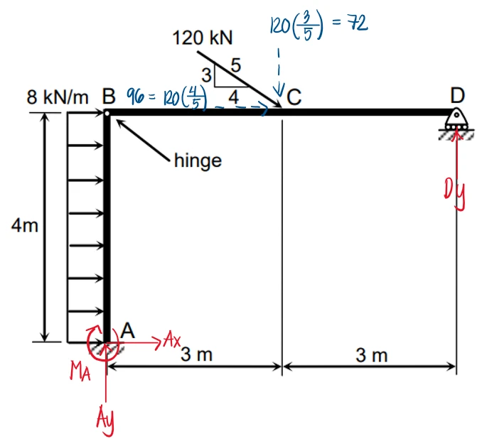
Determine the resultant reactions of the frame shown.

q319

Resultant reaction at D in kN

  1. 36
  2. 50.91
  3. 42
  4. 60.91

Resultant reaction at B in kN

  1. 102.53
  2. 96
  3. 36
  4. 108.66

Resultant reaction at A in kN

  1. 132.97
  2. 128
  3. 160
  4. 167.90

Moment reaction at A in kN-m

  1. 448
  2. 460
  3. 453
  4. 466
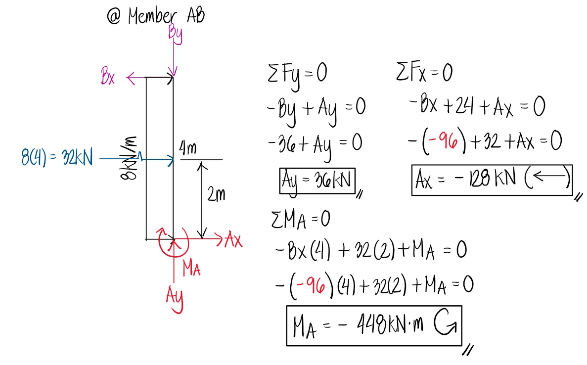
First, we draw the free-body diagram of the structure, considering the external supports. At joint D, we have a roller support, which will have a vertical reaction. At point A, the support is fixed, so there are vertical, horizontal, and moment reactions. In our assumptions of the direction of the external reactions, we use the positive convention (+ for clockwise, upward loads, and rightward loads), so that when the result is negative, we know that the direction would match our conventions for the negative directions. Solution figure We first analyze member BCD. In our free-body diagram, we draw the reactions of the internal hinge at B (pin). We still base our assumptions on our positive convention, so we write Bx going to the right and By going downward. In the solution below, Bx came out as negative. This means that the internal reaction, Bx, is leftward. Next, we compute the resultant reaction at B by using the Pythagorean Theorem. RB is simply the hypotenuse of the force triangle formed by the components of the internal reaction at B. Solution figure Now, in member BCD, we obtained a negative value for Bx, which means that it is actually leftward. However, to avoid redrawing arrows, since this cannot be done conveniently when using a pen, we retain the original direction based on our initial assumptions on member BCD. In member BCD, we wrote Bx as rightward — but it came out to be negative, so it should be leftward; and reversing the sign for member AB, Bx shall act rightward.
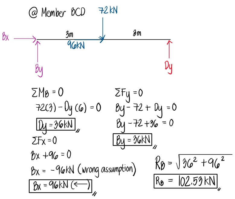
Instead of rewriting the direction of the arrows, we can stick with our first assumption, but to account for the wrong assumption of Bx, we simply use the actual sign obtained in our previous calculation. This is the reason why we use a negative sign for Bx when we substitute it into the equilibrium equations below. Solution figure