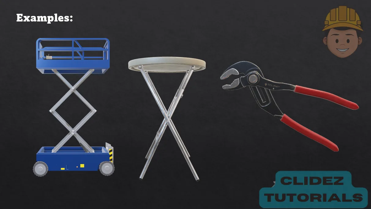
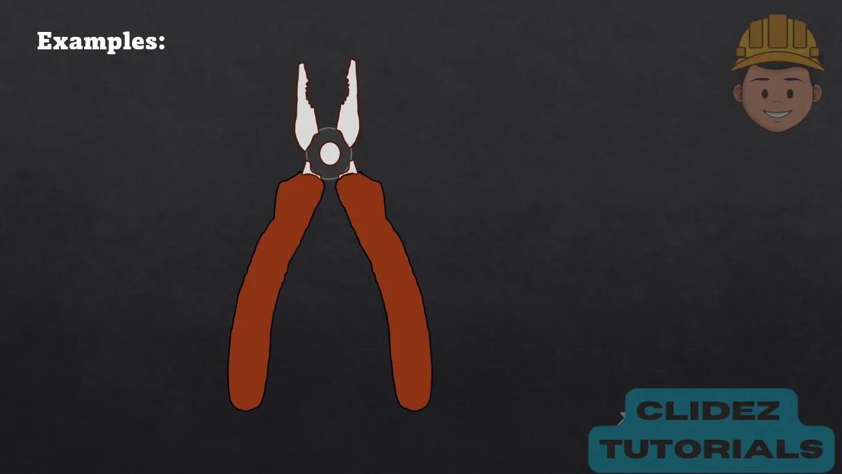
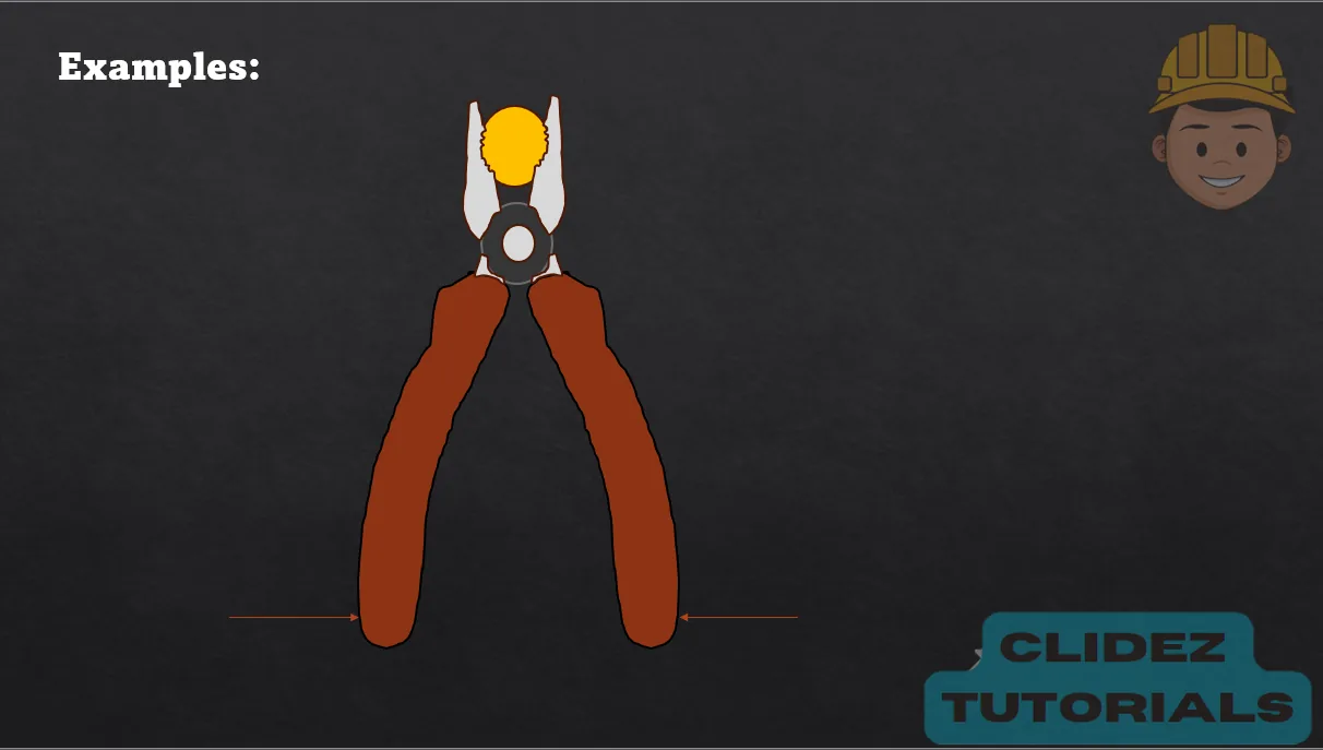
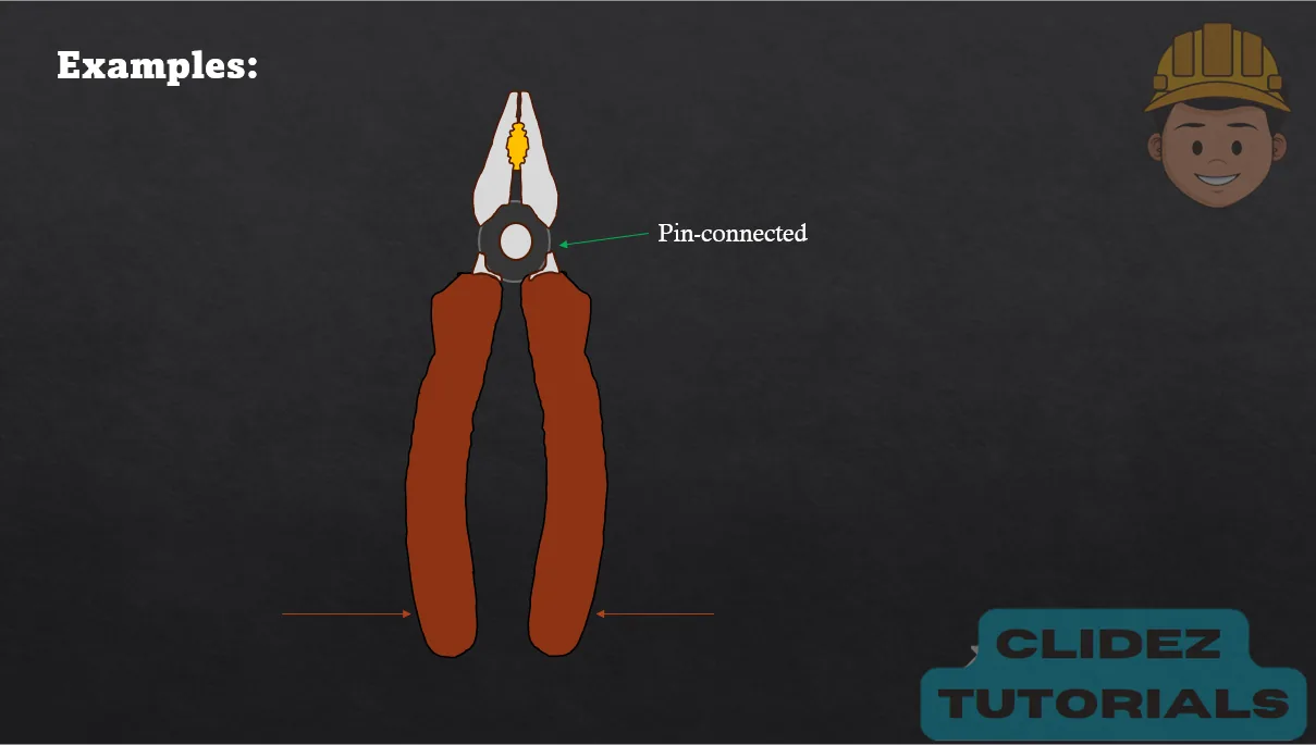
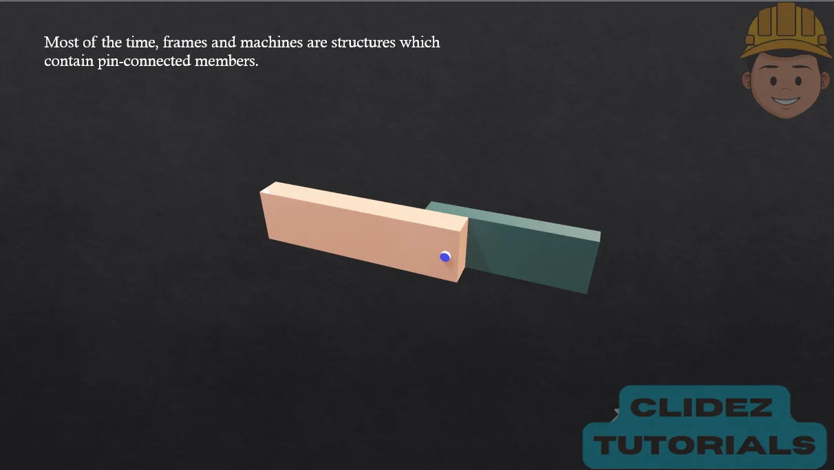
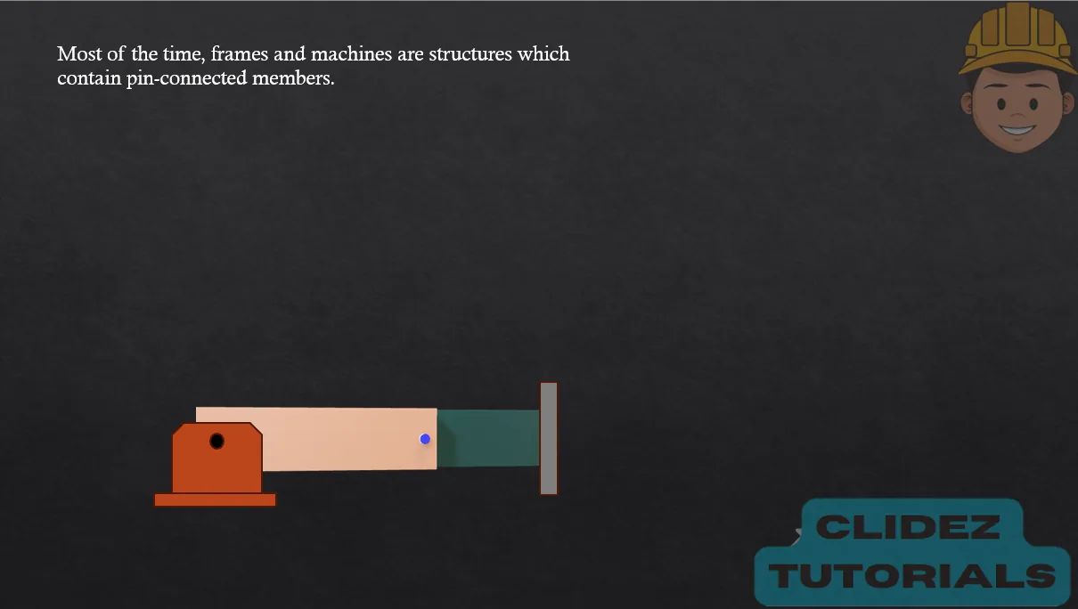
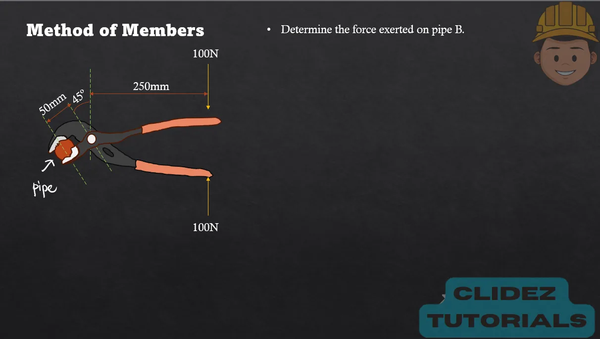
Frames and machines like pliers and wrenches use pin connections to create mechanical advantage—they allow a small applied force at one point to produce a much larger force at another. This is especially helpful when we need to exert forces that would be difficult or impossible with our bare hands, such as tightening bolts or gripping pipes.
The pin joints act as pivots, allowing different members of the frame to rotate and transfer forces efficiently.
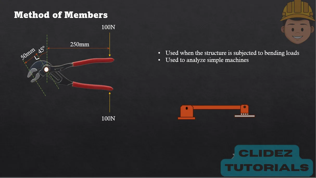
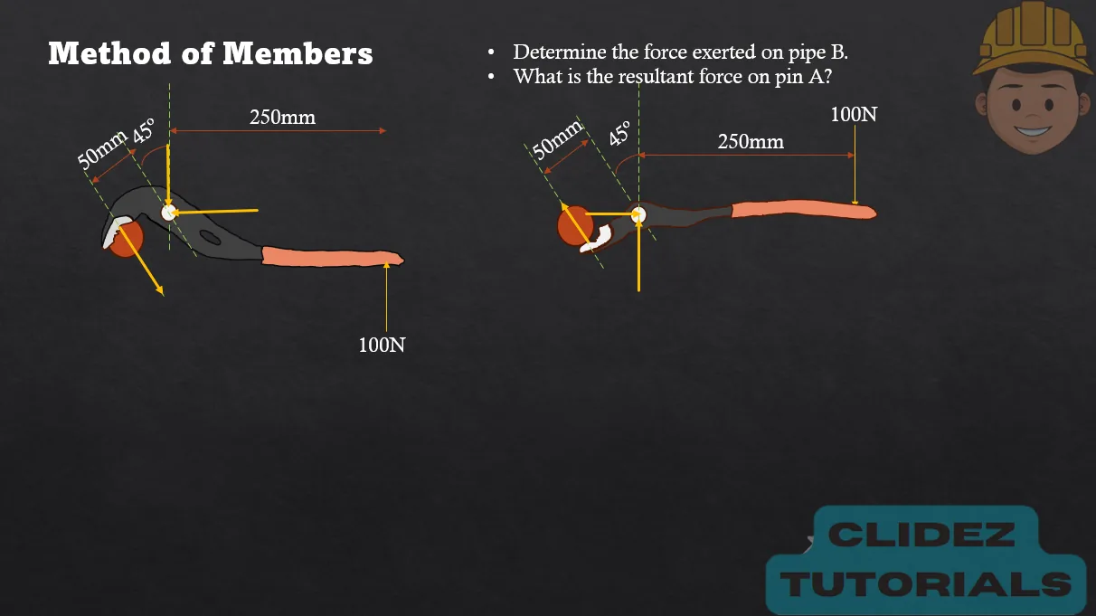
As in the case of the pliers, the input force (from our hand) travels through rigid links and pivots, generating a greater output force at the jaws due to the geometry and relative lengths of the members—shorter output arms and longer input arms multiply the applied force.
This principle is the same behind levers and is fundamental to machines like wrenches, clamps, scissors, and even robotic arms.
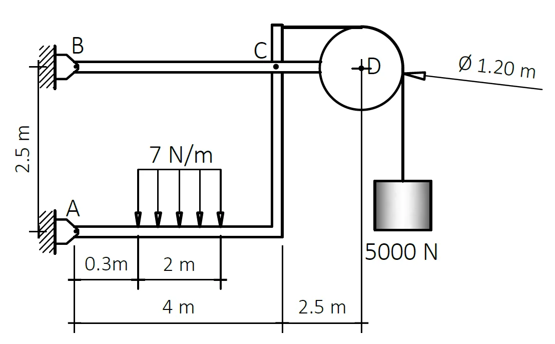
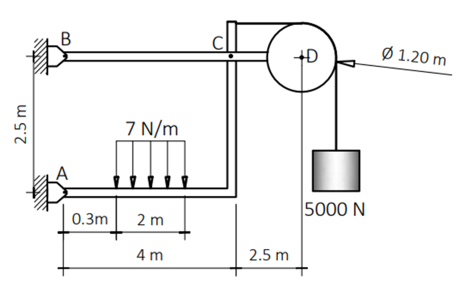
Problem: Frame with Pulley by Method of Members
For the frame shown, the pulley has a mass of 200kg and is frictionless. Neglect the weight of the bars and determine the following:
a. Determine the resultant reaction at D. (8571.432N)
b. Determine the resultant reaction at C. (26812.158N)
c. Determine the resultant reaction at A. (22385.8N)
d. Determine the resultant reaction at B. (19792.695N)
See images:
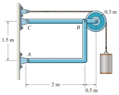
Problem: Frame with Pulley
Determine the resultant reaction at A if the mass of the block is 75kg. (1532.8N)
See images:
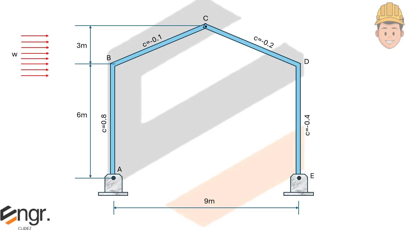
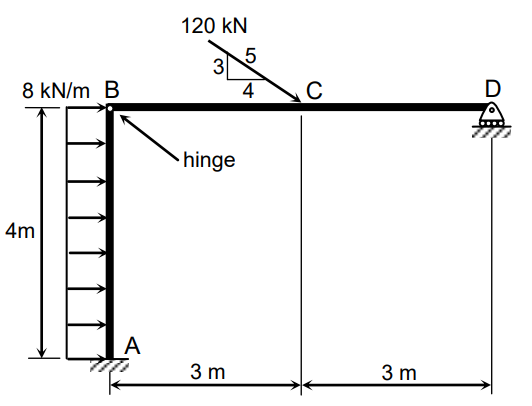
Problem: Frame with Internal Hinge | CE Past Board Exam
The frame shown in the figure is acted on by wind load pressure of p=1.44kPa. These frames are spaced 6m apart.
a. Determine the vertical component of the reaction at A. (27.756kN)
b. Determine the vertical component of the reaction at B. (16.092kN)
c. Determine the total horizontal force acting on the frame. (64.8kN)
See images:
Problem: Beam with Internal Hinge by Method of Members
For the continuous beam shown, P=356kN and w=43.80kN/m.
a. Determine the vertical reaction of the support at A in kN.
b. Determine the reaction of the support at F in kN.
c. Determine the reaction of the support at E in kN.
See images:
Problem:
Refer to the image shown:
See images:
Problem:
Refer to the image shown:
See images:
Problem:
Refer to the image shown:
See images:
Problem: Beam with Internal Hinge by Method of Members
See images:
Problem (Frame support reactions):
A rigid frame is supported by a pin at A and a roller at B, 4m apart. A 12kN vertical load acts 1m from A. Determine the vertical reactions.
A frame member contains an internal hinge at C. The left segment has an 8kN downward load located 2m from pin A and the hinge C is 4m from A. Determine the vertical force at C on the left segment.
Take moments about A for the left segment. The hinge transmits force but no moment.
\[
\begin{aligned}
\sum M_A=0:\quad C_y(4)-8(2)&=0 \\
C_y&=4\ \text{kN}
\end{aligned}
\]
$\boxed{C_y=4\ \text{kN upward on the left segment}}$
🧭 Jump to:
Scroll to zoom
Exam Generator Problems
Additional board-style practice items for this topic.