CE Board Exam Randomizer

⬅ Back to Subject Topics

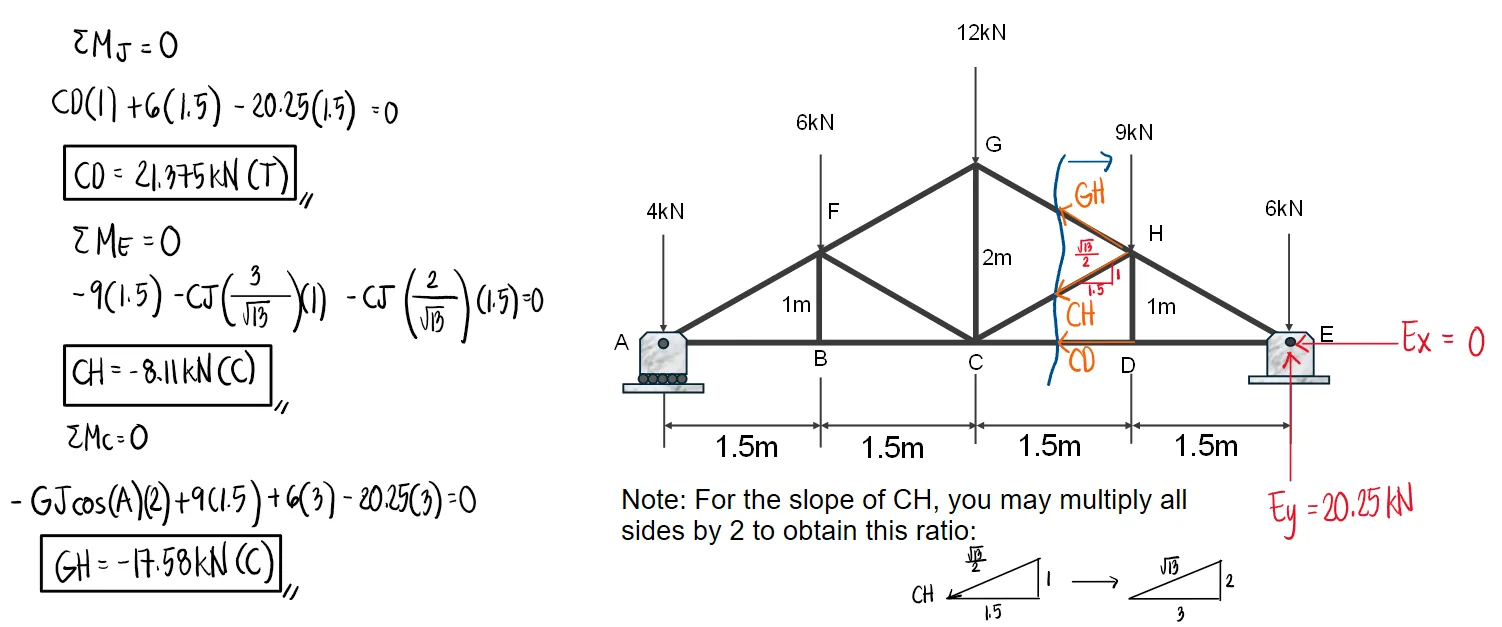
Analysis of Trusses (Method of Sections)

Concept Concept Concept Concept Concept Concept Concept Concept Concept Concept Concept

Problem:

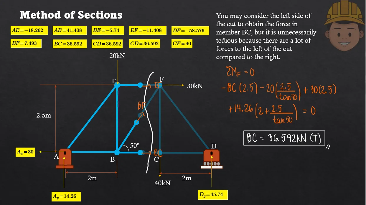
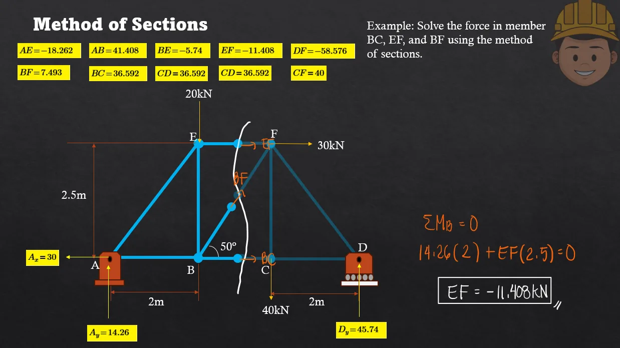
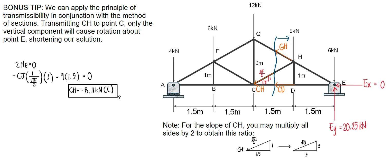
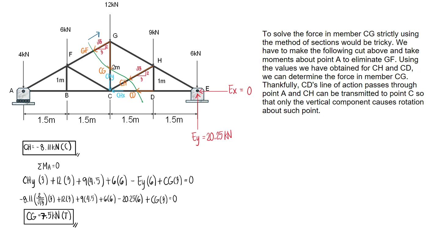
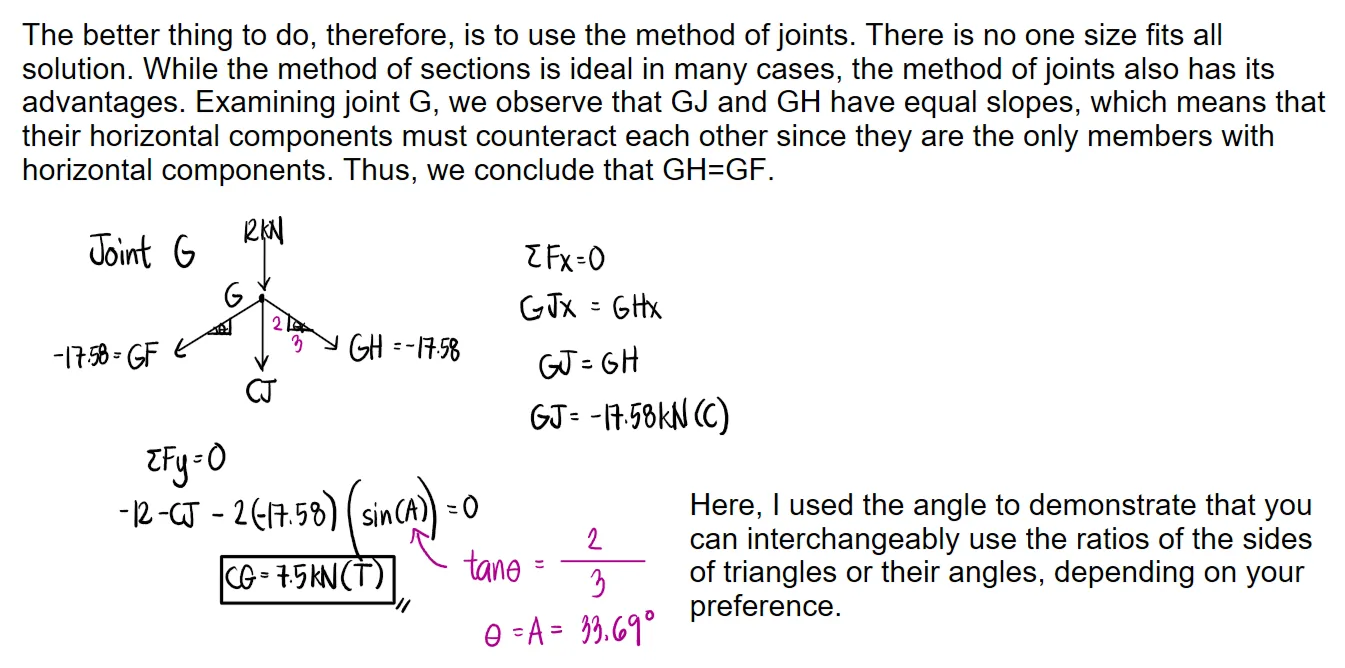
Determine the force in members CD, CH, GH, and CG and state if these members are in tension or compression.
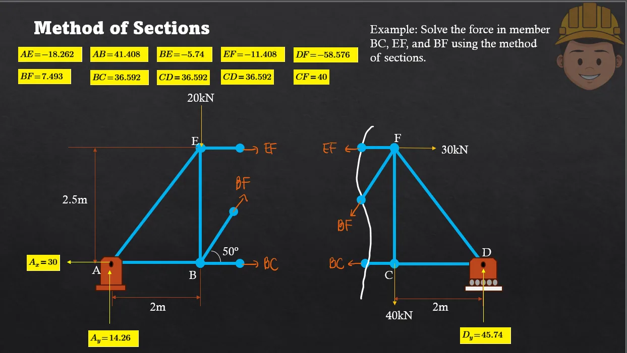
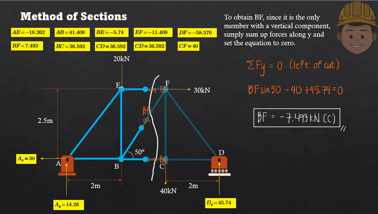
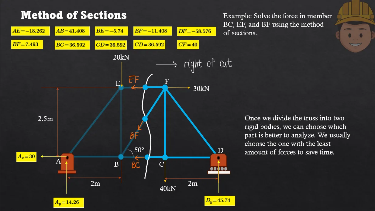
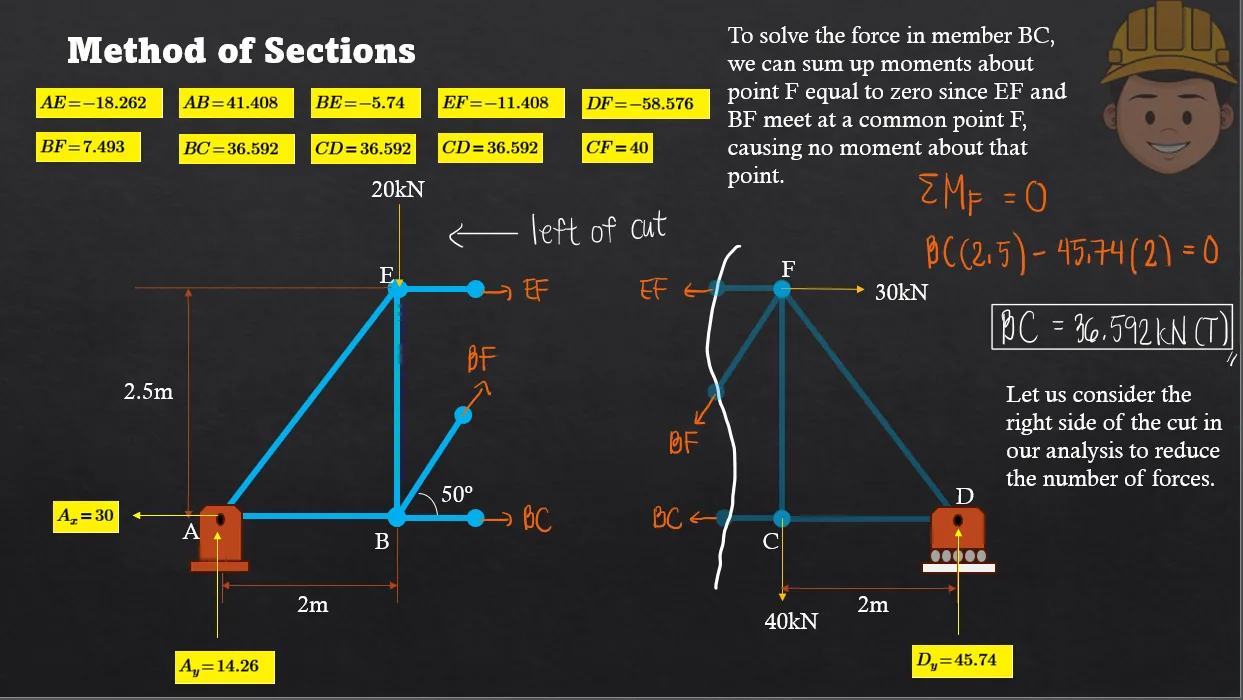
Analysis of Trusses: Method of Sections | Statics of Rigid Bodies – Problem 1: – Diagram Analysis of Trusses: Method of Sections | Statics of Rigid Bodies – Problem 1: – Diagram Analysis of Trusses: Method of Sections | Statics of Rigid Bodies – Problem 1: – Diagram

See images:

Analysis of Trusses: Method of Sections | Statics of Rigid Bodies – Problem 1: – Diagram Analysis of Trusses: Method of Sections | Statics of Rigid Bodies – Problem 1: – Diagram Analysis of Trusses: Method of Sections | Statics of Rigid Bodies – Problem 1: – Diagram Analysis of Trusses: Method of Sections | Statics of Rigid Bodies – Problem 1: – Diagram Analysis of Trusses: Method of Sections | Statics of Rigid Bodies – Problem 1: – Diagram

Problem:

Analysis of Trusses: Method of Sections | Statics of Rigid Bodies – Problem 2: – Diagram Analysis of Trusses: Method of Sections | Statics of Rigid Bodies – Problem 2: – Diagram Analysis of Trusses: Method of Sections | Statics of Rigid Bodies – Problem 2: – Diagram

See images:

Analysis of Trusses: Method of Sections | Statics of Rigid Bodies – Problem 2: – Diagram Analysis of Trusses: Method of Sections | Statics of Rigid Bodies – Problem 2: – Diagram Analysis of Trusses: Method of Sections | Statics of Rigid Bodies – Problem 2: – Diagram Analysis of Trusses: Method of Sections | Statics of Rigid Bodies – Problem 2: – Diagram

Problem:

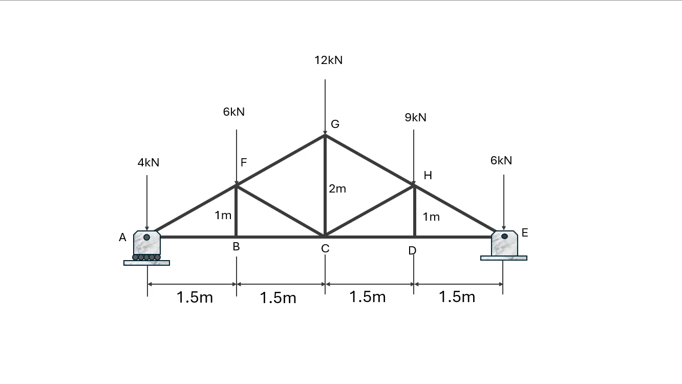
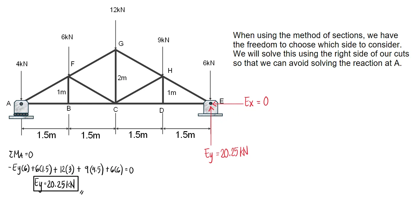
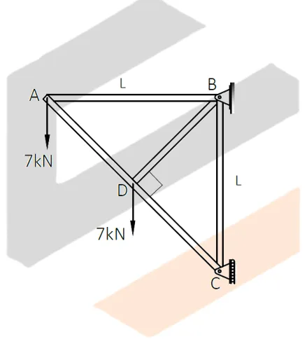
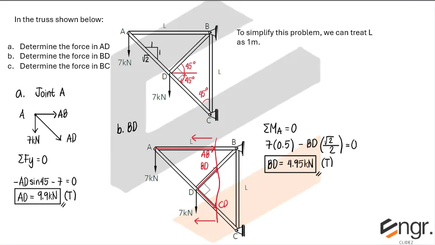
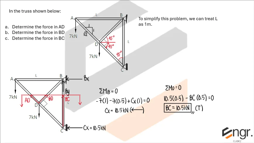
In the truss shown below:
a. Determine the force in AD
b. Determine the force in BD
c. Determine the force in BC.

Analysis of Trusses: Method of Sections | Statics of Rigid Bodies – Problem 3: – Diagram Analysis of Trusses: Method of Sections | Statics of Rigid Bodies – Problem 3: – Diagram Analysis of Trusses: Method of Sections | Statics of Rigid Bodies – Problem 3: – Diagram

See images:

Analysis of Trusses: Method of Sections | Statics of Rigid Bodies – Problem 3: – Diagram Analysis of Trusses: Method of Sections | Statics of Rigid Bodies – Problem 3: – Diagram Analysis of Trusses: Method of Sections | Statics of Rigid Bodies – Problem 3: – Diagram Analysis of Trusses: Method of Sections | Statics of Rigid Bodies – Problem 3: – Diagram

Problem: Maximum Value of the Applied P based on Given Capacities of Members

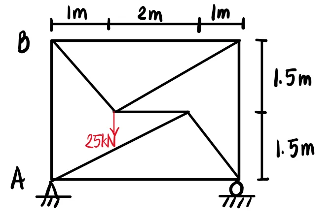
Given the truss shown in the figure,

Analysis of Trusses: Method of Sections | Statics of Rigid Bodies – Problem 4: – Diagram

a. If the strength of the truss is governed by the compressive load of member BD which is 100 kN, compute the maximum value of P in kilonewtons.
a. 25
b. 30
c. 20
d. Not in the list

b. If its strength is governed by the tensile force of member CD of 50 kN, compute the maximum value of P in kilonewtons.
a. 20
b. 50
c. 30
d. 40

c. If its strength is governed by the tensile force of member CF of 75 kN, compute the maximum value of P in kilonewtons.
a. 25
b. 30
c. 20
d. 15

Analysis of Trusses: Method of Sections | Statics of Rigid Bodies – Problem 4: – Diagram Analysis of Trusses: Method of Sections | Statics of Rigid Bodies – Problem 4: – Diagram

See images:

Analysis of Trusses: Method of Sections | Statics of Rigid Bodies – Problem 4: – Diagram Analysis of Trusses: Method of Sections | Statics of Rigid Bodies – Problem 4: – Diagram Analysis of Trusses: Method of Sections | Statics of Rigid Bodies – Problem 4: – Diagram Analysis of Trusses: Method of Sections | Statics of Rigid Bodies – Problem 4: – Diagram

Problem:

Refer to the image shown:

Analysis of Trusses: Method of Sections | Statics of Rigid Bodies – Problem 5: – Diagram Analysis of Trusses: Method of Sections | Statics of Rigid Bodies – Problem 5: – Diagram Analysis of Trusses: Method of Sections | Statics of Rigid Bodies – Problem 5: – Diagram

See images:

Analysis of Trusses: Method of Sections | Statics of Rigid Bodies – Problem 5: – Diagram Analysis of Trusses: Method of Sections | Statics of Rigid Bodies – Problem 5: – Diagram Analysis of Trusses: Method of Sections | Statics of Rigid Bodies – Problem 5: – Diagram Analysis of Trusses: Method of Sections | Statics of Rigid Bodies – Problem 5: – Diagram

Problem:

Refer to the image shown:

Analysis of Trusses: Method of Sections | Statics of Rigid Bodies – Problem 6: – Diagram Analysis of Trusses: Method of Sections | Statics of Rigid Bodies – Problem 6: – Diagram Analysis of Trusses: Method of Sections | Statics of Rigid Bodies – Problem 6: – Diagram

See images:

Analysis of Trusses: Method of Sections | Statics of Rigid Bodies – Problem 6: – Diagram Analysis of Trusses: Method of Sections | Statics of Rigid Bodies – Problem 6: – Diagram Analysis of Trusses: Method of Sections | Statics of Rigid Bodies – Problem 6: – Diagram Analysis of Trusses: Method of Sections | Statics of Rigid Bodies – Problem 6: – Diagram

Problem:

Refer to the image shown:

Analysis of Trusses: Method of Sections | Statics of Rigid Bodies – Problem 7: – Diagram Analysis of Trusses: Method of Sections | Statics of Rigid Bodies – Problem 7: – Diagram Analysis of Trusses: Method of Sections | Statics of Rigid Bodies – Problem 7: – Diagram

See images:

Analysis of Trusses: Method of Sections | Statics of Rigid Bodies – Problem 7: – Diagram Analysis of Trusses: Method of Sections | Statics of Rigid Bodies – Problem 7: – Diagram Analysis of Trusses: Method of Sections | Statics of Rigid Bodies – Problem 7: – Diagram Analysis of Trusses: Method of Sections | Statics of Rigid Bodies – Problem 7: – Diagram

Problem:

Refer to the image shown:

Analysis of Trusses: Method of Sections | Statics of Rigid Bodies – Problem 8: – Diagram Analysis of Trusses: Method of Sections | Statics of Rigid Bodies – Problem 8: – Diagram Analysis of Trusses: Method of Sections | Statics of Rigid Bodies – Problem 8: – Diagram

See images:

Analysis of Trusses: Method of Sections | Statics of Rigid Bodies – Problem 8: – Diagram Analysis of Trusses: Method of Sections | Statics of Rigid Bodies – Problem 8: – Diagram Analysis of Trusses: Method of Sections | Statics of Rigid Bodies – Problem 8: – Diagram Analysis of Trusses: Method of Sections | Statics of Rigid Bodies – Problem 8: – Diagram
-->

Problem (Section member from moment):

A truss section cuts member DE. Taking moments about a joint where the other two cut members intersect gives a perpendicular distance of 3m from DE. If the external moment about that joint is 45kN-m clockwise, determine the force in DE.

Use moment equilibrium of the cut free body.

\[ \begin{aligned} \sum M=0:\quad F_{DE}(3)-45&=0 \\ F_{DE}&=15\ \text{kN} \end{aligned} \] $\boxed{F_{DE}=15\ \text{kN}}$

Problem (Section with inclined member components):

A cut exposes an inclined member with a 3-4-5 slope. The vertical equilibrium of the free body requires an upward component of 24kN from this member. Determine the member force.

The vertical component is four-fifths of the member force.

\[ \begin{aligned} F\left({4\over5}\right)&=24 \\ F&=30\ \text{kN} \end{aligned} \] $\boxed{F=30\ \text{kN}}$

Problem (Solving two cut members by sections):

After cutting a truss, horizontal equilibrium gives F1 + 0.6F2 = 18, and vertical equilibrium gives 0.8F2 = 16. Determine F1 and F2.

Solve the vertical equation first, then substitute into the horizontal equation.

\[ \begin{aligned} 0.8F_2&=16 \\ F_2&=20\ \text{kN} \\ F_1+0.6(20)&=18 \\ F_1&=6\ \text{kN} \end{aligned} \] $\boxed{F_1=6\ \text{kN}},\qquad \boxed{F_2=20\ \text{kN}}$
Scroll to zoom