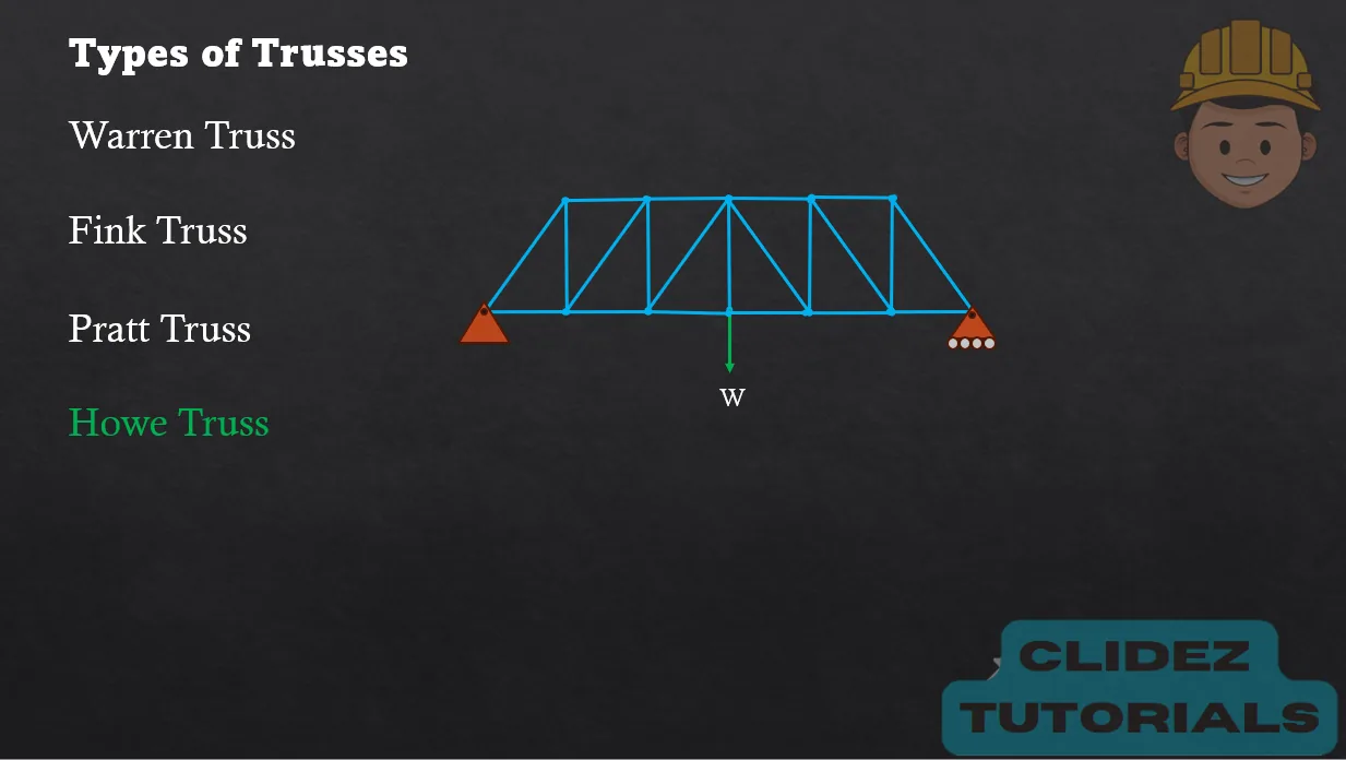
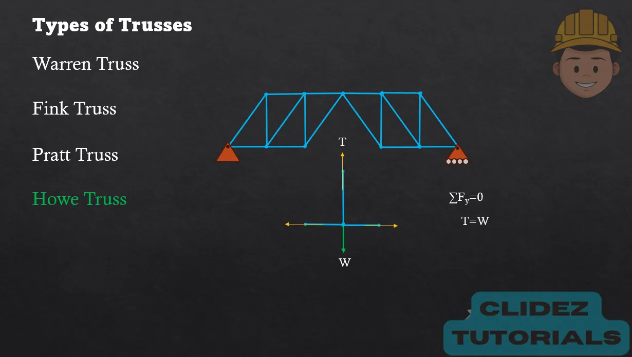
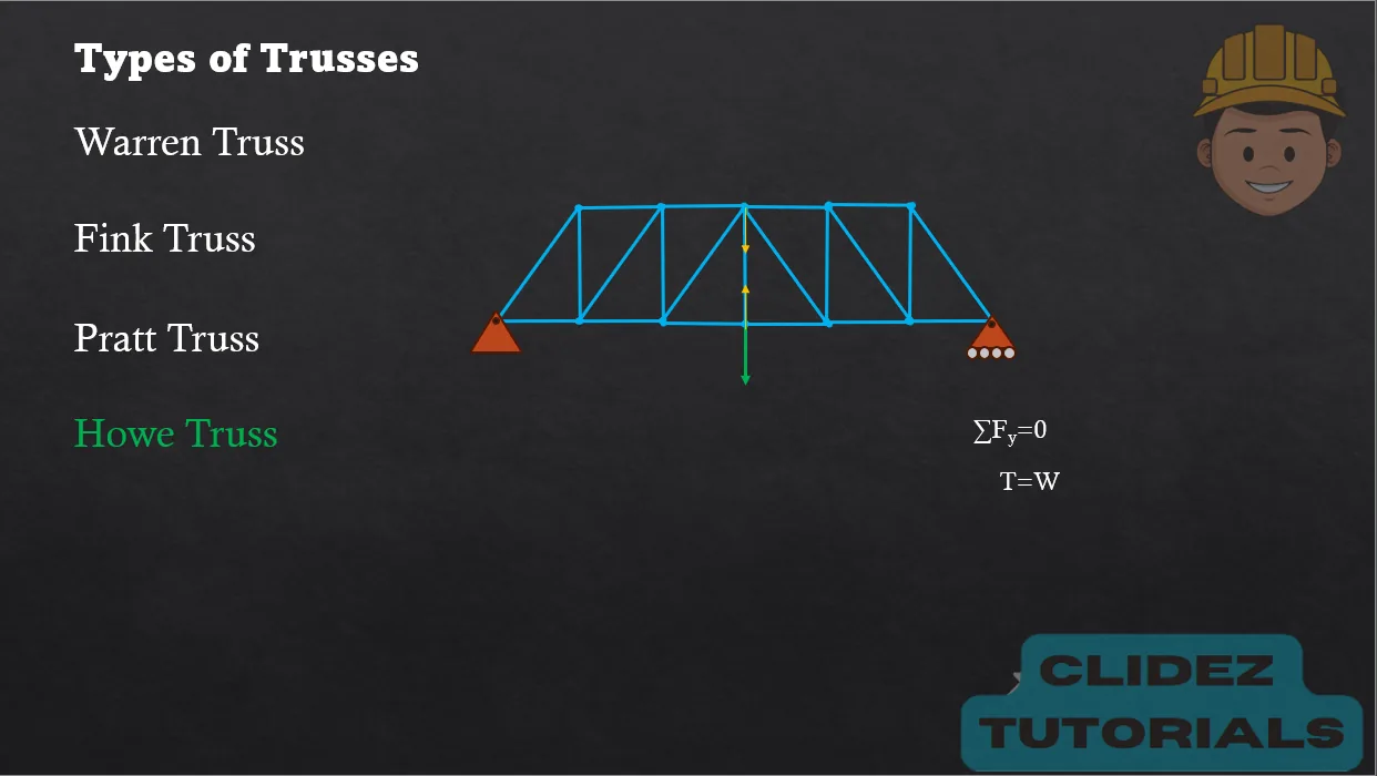
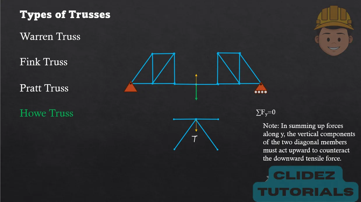
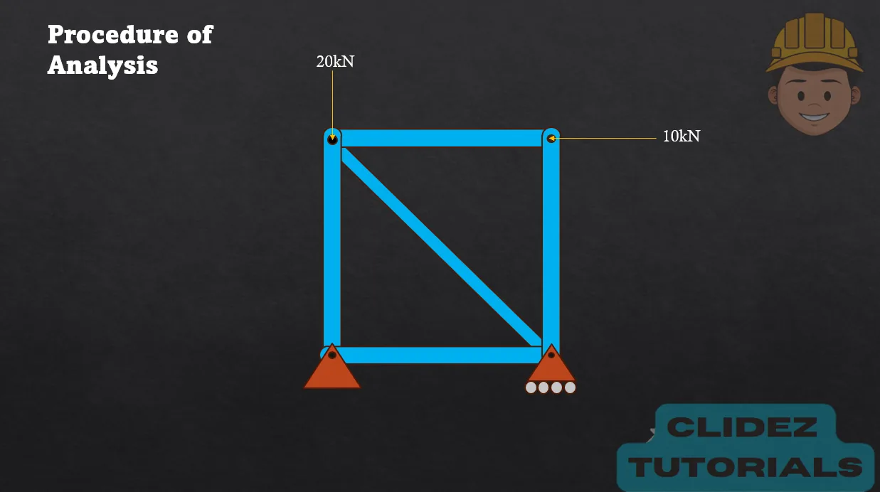
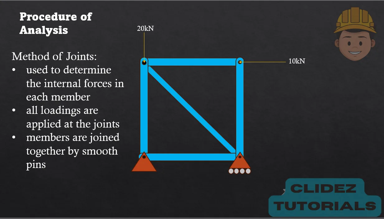
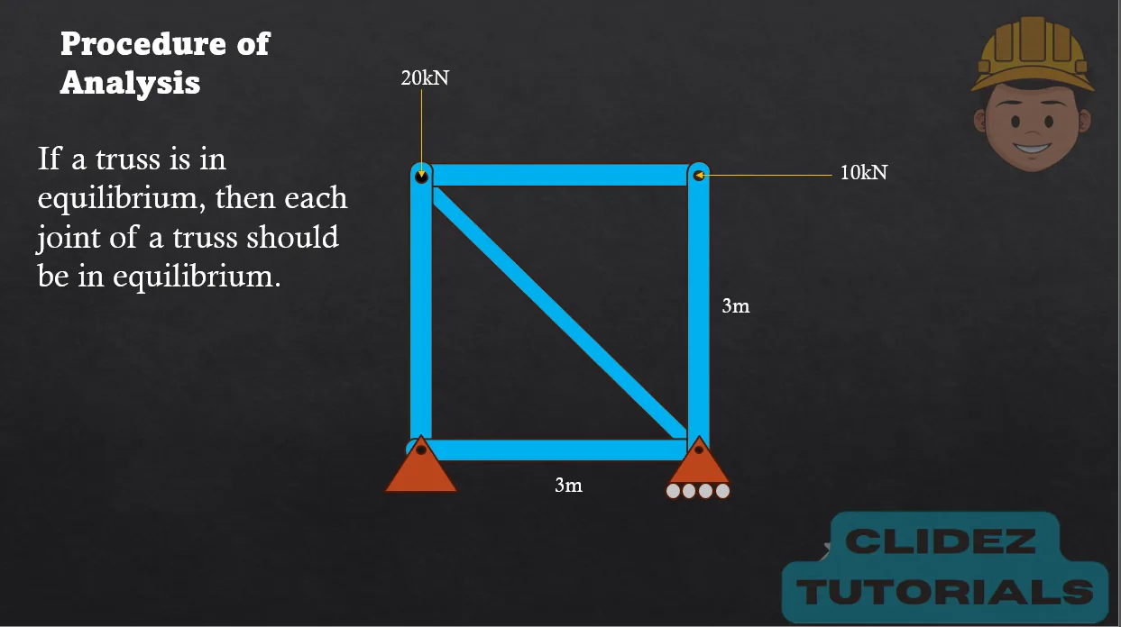
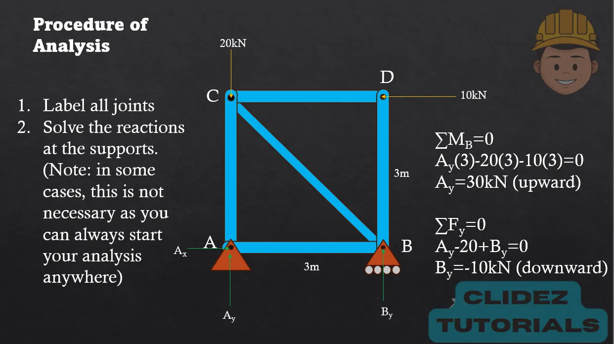
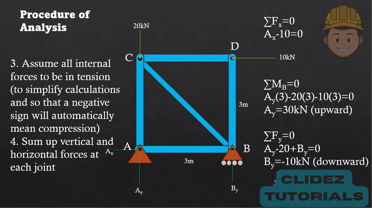
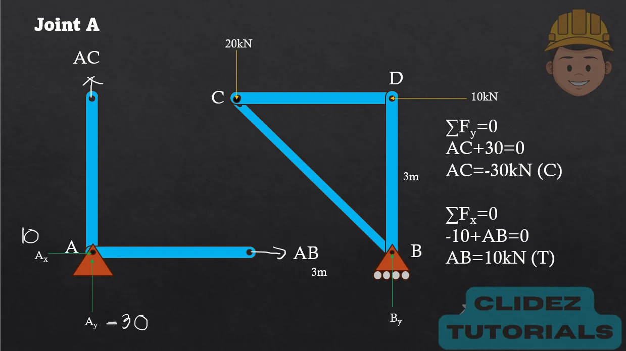
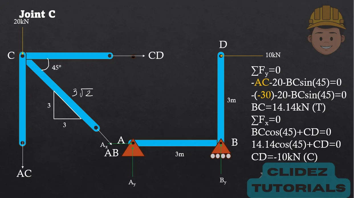
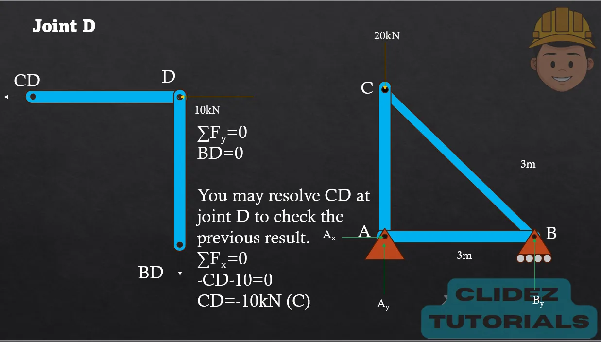
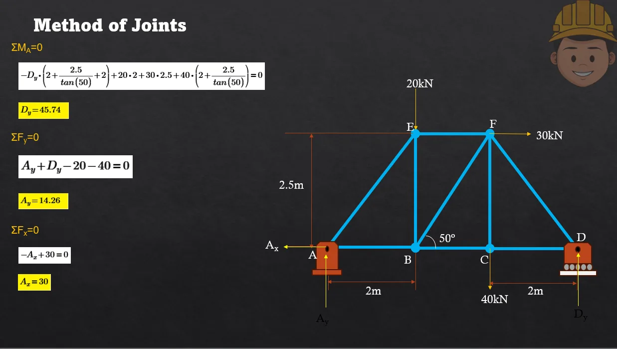
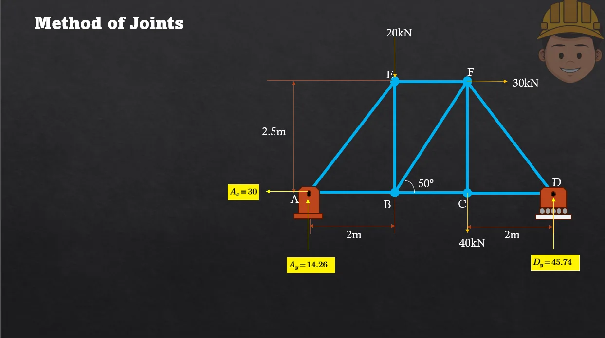
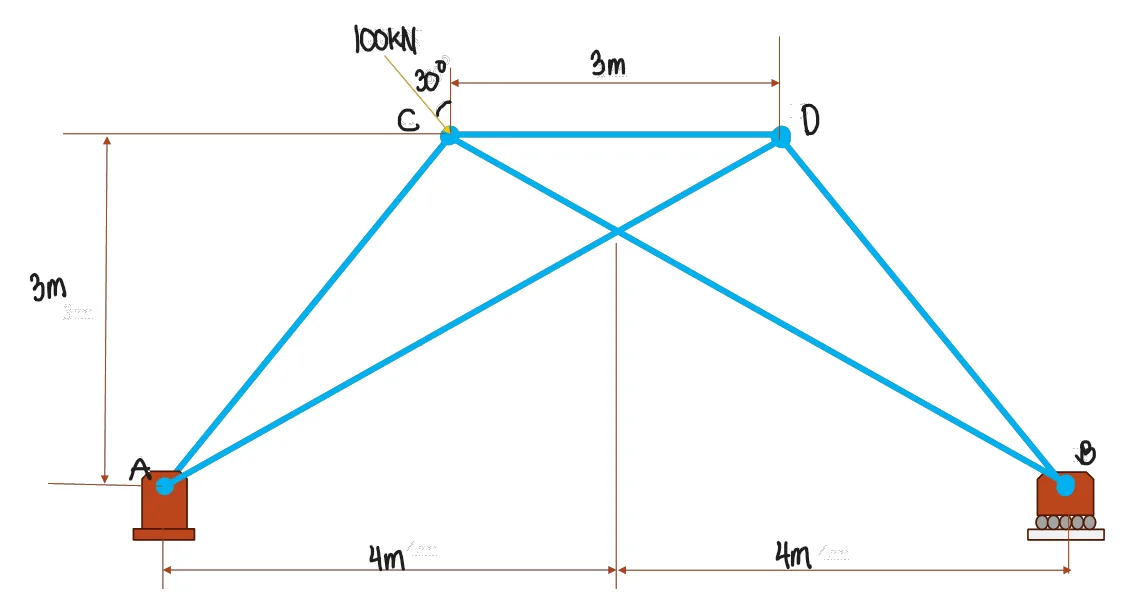
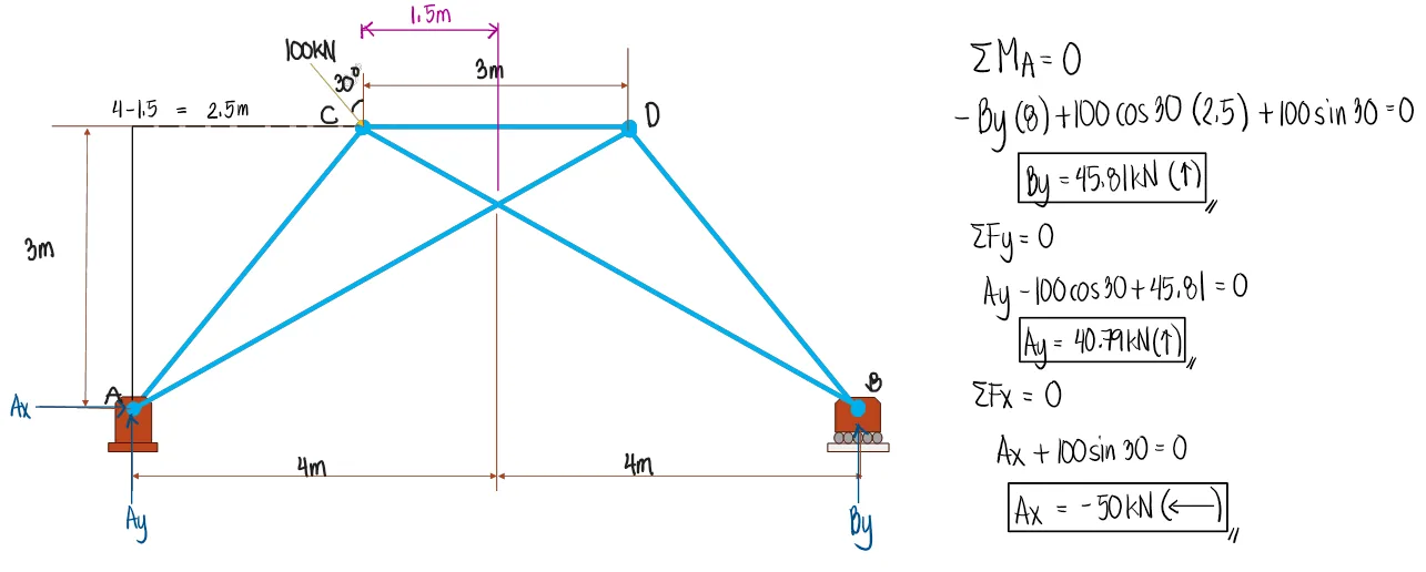
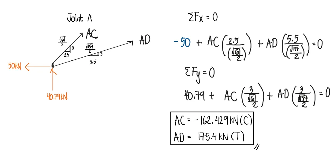
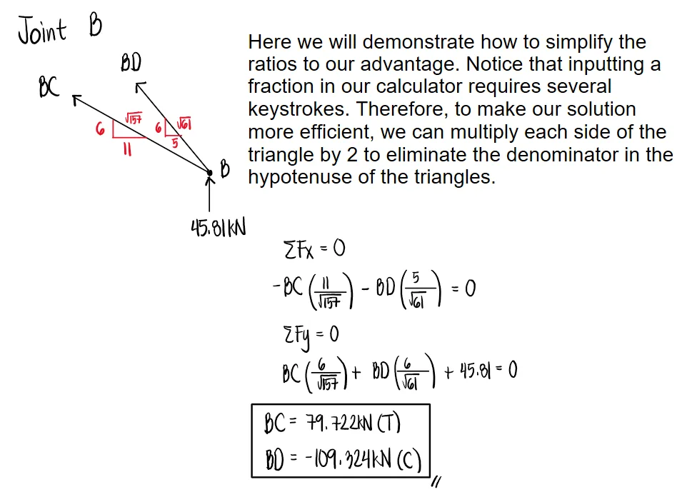
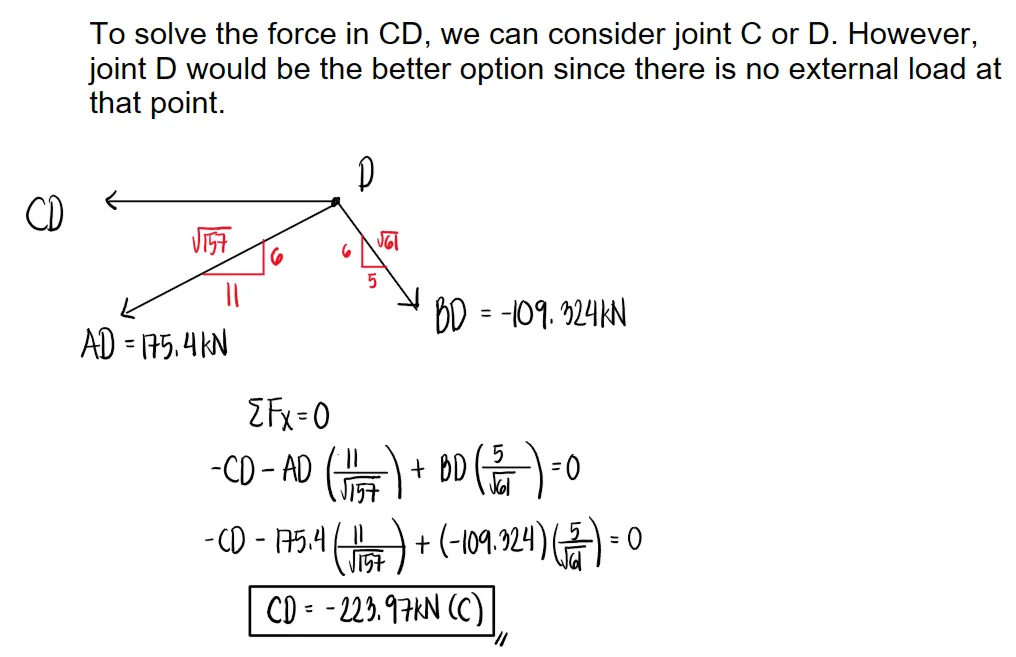
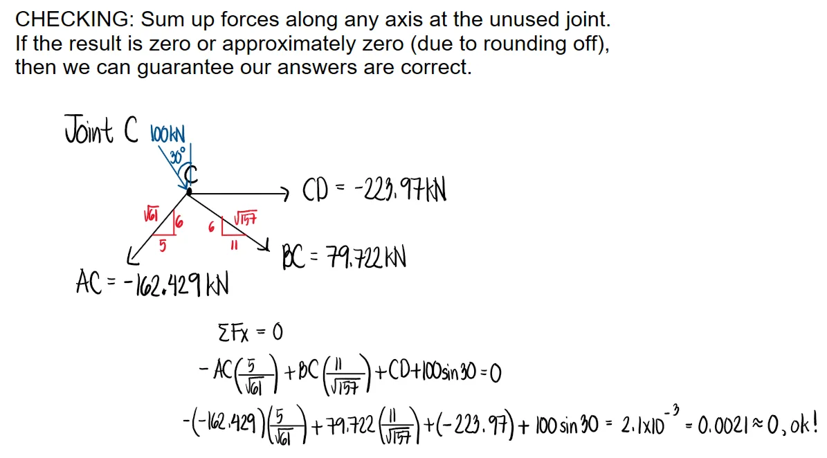
For the given truss, determine the forces in all members.
See images:
Problem:
Refer to the image shown:
See images:
-->
Problem (Symmetric truss by joint method):
A triangular truss has supports at A and C, 6m apart, and joint B located 3m horizontally from A and 4m above AC. A 20kN downward load acts at B. Determine the forces in AB and BC.
The geometry of each inclined member is a 3-4-5 triangle. By symmetry, the vertical reactions are 10kN each.
Problem (Joint with vertical and horizontal loads):
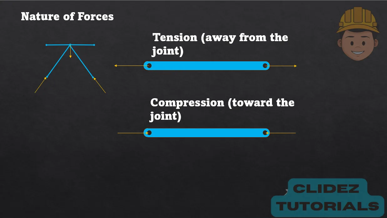
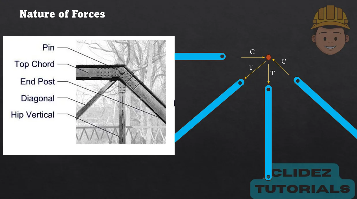
At a truss joint, member AB is horizontal to the left and member AC is inclined 30° above the horizontal to the right. A 6kN downward load and a 4kN horizontal load to the right act at the joint. Determine the member forces, assuming tension pulls away from the joint.
For the truss shown below, the allowable forces for each member are the ff. BC=70kN (T) EC=60kN (C) DE=25kN (C).
Compute the maximum safe value of P (in kN) if the strength of member EC governs.
52
61
43
48
Compute the maximum safe value of P (in kN) if the strength of member BC governs.
61
43
52
48
Compute the maximum safe value of P (in kN) if the strength of member DE governs.
43
52
61
48
Because the truss is linear elastic, every member force is proportional to the applied load P. Joint equilibrium gives $F_{EC}=1.154P$ (compression), $F_{BC}=1.148P$ (tension), and $F_{DE}=0.581P$ (compression).
Part 1. $1.154P\le60$, so $P=\boxed{52\text{ kN}}$ when EC governs.
Part 2. $1.148P\le70$, so $P=\boxed{61\text{ kN}}$ when BC governs.
Part 3. $0.581P\le25$, so $P=\boxed{43\text{ kN}}$ when DE governs.
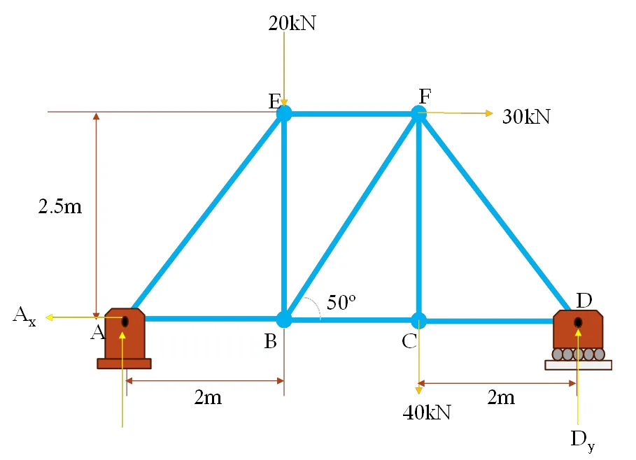
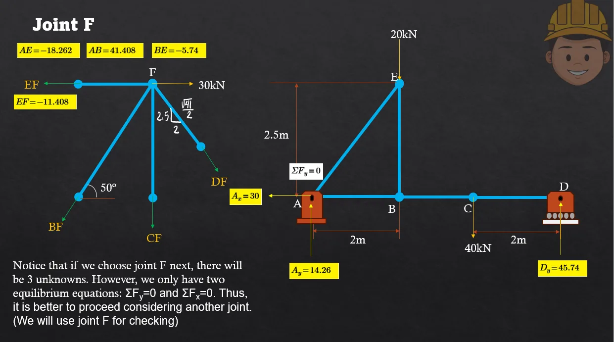
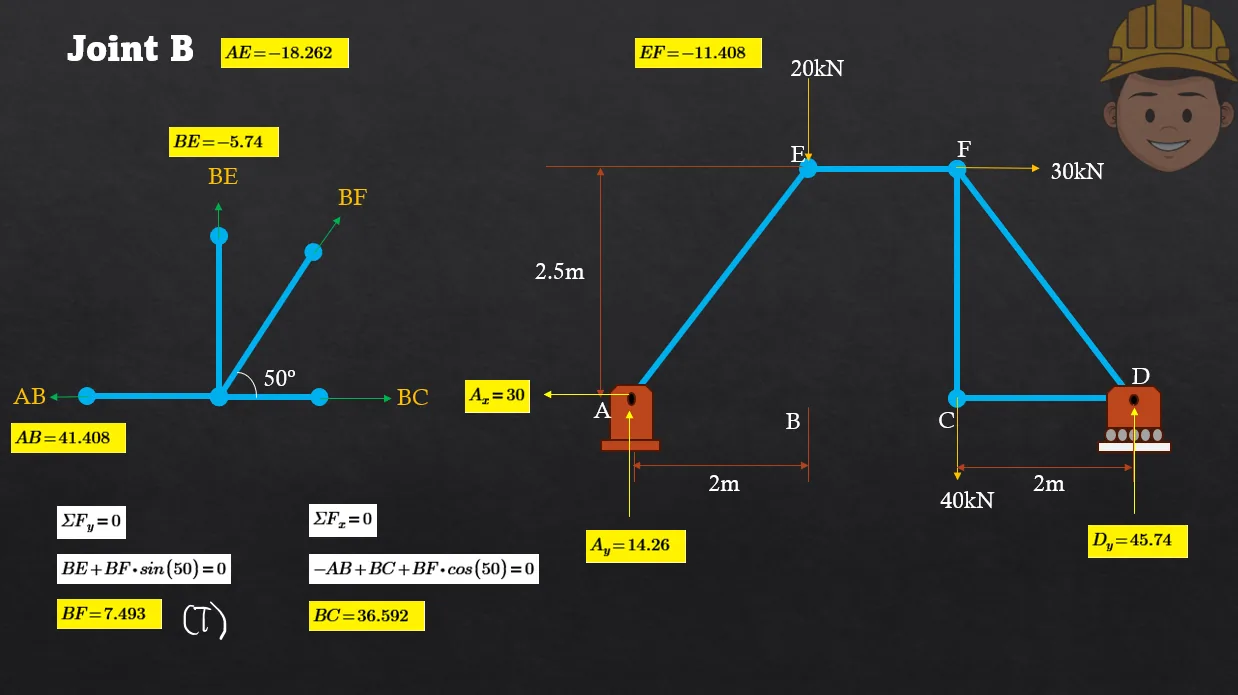
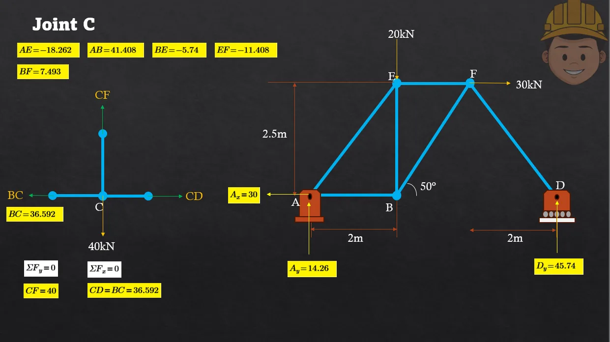
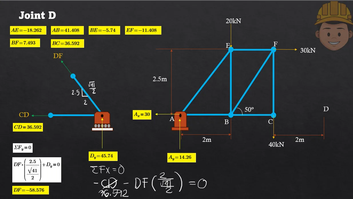
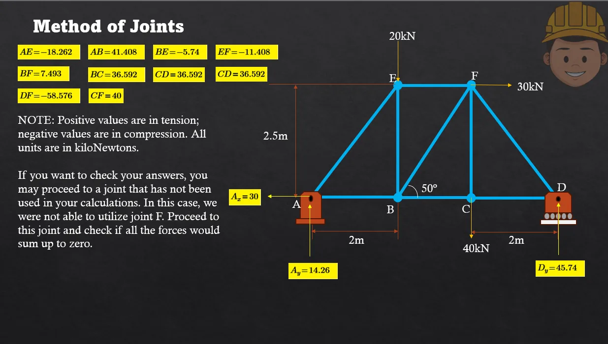
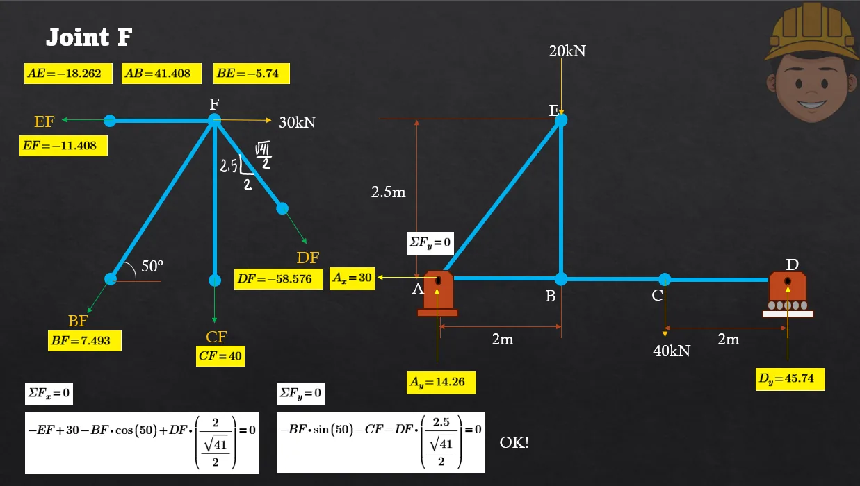
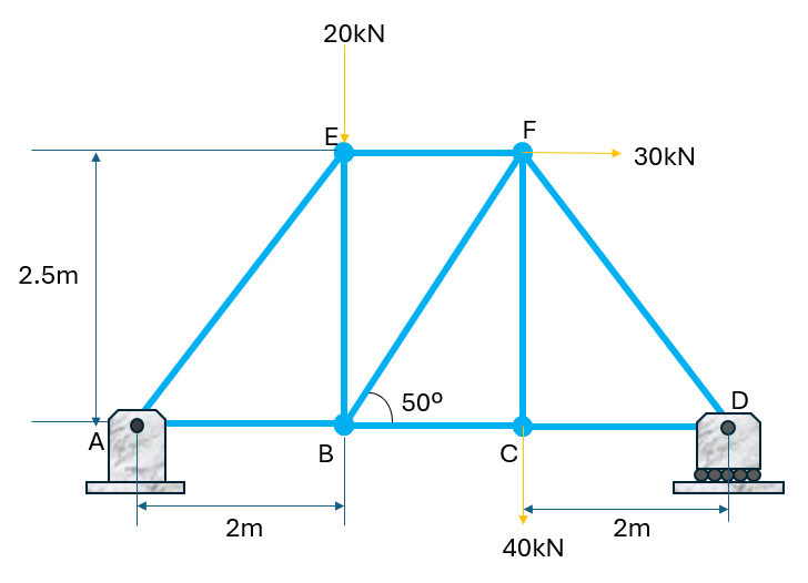
For the truss shown, determine the forces in all members by using the method of joints/sections.
Force in AB
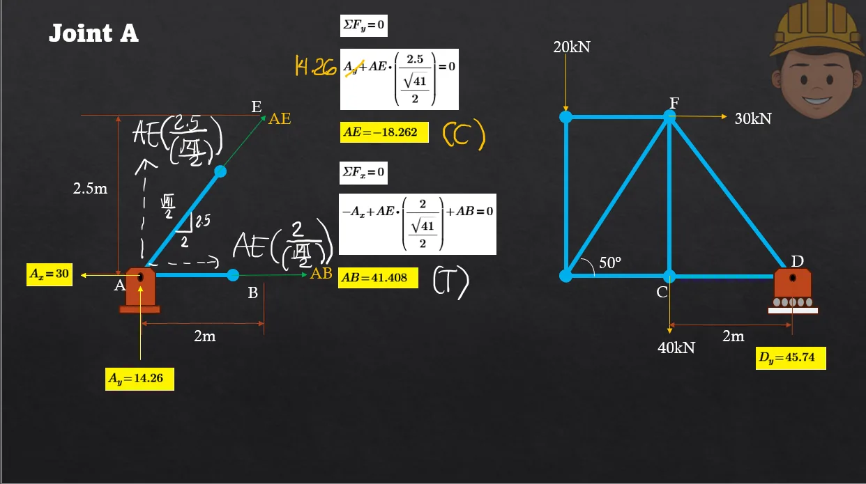
41.408 (T)
41.408 (C)
36.592 (T)
36.592 (C)
Force in AE
18.262 (C)
18.262 (T)
11.408 (C)
11.408 (T)
Force in BE
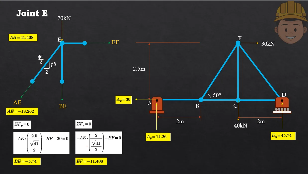
5.74 (C)
5.74 (T)
7.493 (T)
7.493 (C)
Force in EF
11.408 (C)
11.408 (T)
18.262 (C)
18.262 (T)
Force in BF
7.493 (T)
7.493 (C)
5.74 (C)
5.74 (T)
Force in BC
36.592 (T)
36.592 (C)
40 (T)
40 (C)
Force in CD
36.592 (T)
36.592 (C)
40 (T)
40 (C)
Force in DF
58.576 (C)
58.576 (T)
41.408 (T)
41.408 (C)
Force in CF
40 (T)
40 (C)
41.408 (T)
41.408 (C)
### Truss-member forces
First obtain the support reactions from the complete truss. Then apply $\sum F_x=0$ and $\sum F_y=0$ joint by joint, starting at joints $A$ and $D$. A positive result denotes tension; a negative result denotes compression.
$$AB=\boxed{41.408 \text{kN (T)}},\quad AE=\boxed{18.262 \text{kN (C)}},\quad BE=\boxed{5.74 \text{kN (C)}},$$
$$EF=\boxed{11.408 \text{kN (C)}},\quad BF=\boxed{7.493 \text{kN (T)}},$$
$$BC=CD=\boxed{36.592 \text{kN (T)}},\quad DF=\boxed{58.576 \text{kN (C)}},$$
$$CF=\boxed{40 \text{kN (T)}}.$$
The $20\text{-kN}$ load is $20^\circ$ below the horizontal. Resolve it at joint $C$: $$P_x=20\cos20^\circ=18.79\text{ kN},\qquad P_y=20\sin20^\circ=6.84\text{ kN}$$
Member $AC$ At joint $C$, member $AC$ is vertical. Its force balances the vertical component of the load: $$F_{AC}=P_y=6.84\text{ kN}$$ Thus $AC$ is in tension.
Member $AB$ The horizontal member $BC$ carries $P_x=18.79\text{ kN}$. At joint $B$, the horizontal component of member $AB$, which is at $60^\circ$ to the horizontal, balances this force: $$F_{AB}\cos60^\circ=18.79$$ $$F_{AB}=\frac{18.79}{0.5}=37.59\text{ kN}\approx38\text{ kN}$$ The direction required at joint $B$ makes $AB$ a compression member.
Therefore, $F_{AB}=\mathbf{38\text{ kN}}$ (compression) and $F_{AC}=\mathbf{6.84\text{ kN}}$ (tension).
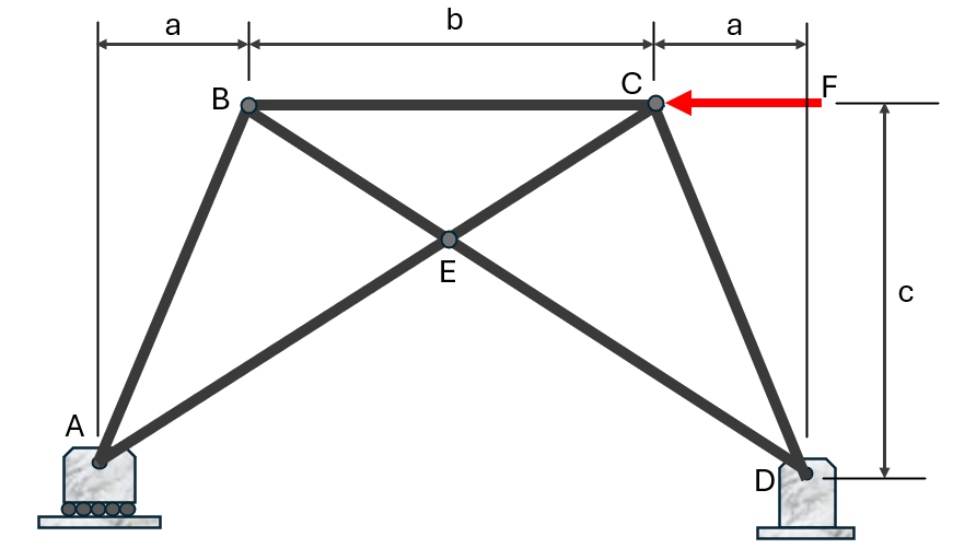
The truss shown is subjected to a lateral load of F=12kN.
a=1.5m
b=4m
c=3.5m
Determine the reaction at A in kN.
6
7
8
9
Determine the force in member AE, in kN.
4.19 (T)
1.91 (T)
14.40 (C)
8.98 (C)
Determine the reaction at D, in kN.
13.4
6.0
12.0
9.1
Resolve the 12-kN lateral load and use $\sum F_x=0$, $\sum F_y=0$, and moments for the truss geometry. The support reactions are $A=6$ kN and $D=13.4$ kN. Joint equilibrium at $A$ gives $F_{AE}=4.19$ kN in tension. Therefore: 6 kN, 4.19 kN (T), and 13.4 kN.
Question Bank: q624
PSAD - Statics / Analysis of Trusses / Mastermatician
Refer to the figure shown. Diagonals BH, CG, HD, and CI are flexible cables and are, therefore, only capable of carrying tensile forces.
P1=2.5kN
P2=1.2kN
P3=1.2kN
L1=3m
L2=2.25m
L3=3m
Determine the force in member HD.
0.000
0.800
0.784
0.792
Determine the force in member CI.
0.800
0.000
0.792
0.784
What is the force in member BH?
0.000
0.800
0.792
0.784
What is the force in member CG?
0.792
0.000
0.800
0.784
Because the diagonals are cables, any negative result means the cable is slack and carries zero force. Solve the panel-joint equilibrium equations with $P_1=2.5$, $P_2=P_3=1.2$ kN. The results are $F_{HD}=0$, $F_{CI}=0.800$ kN, $F_{BH}=0$, and $F_{CG}=0.792$ kN. Thus: 0.000 kN, 0.800 kN, 0.000 kN, and 0.792 kN.
Question Bank: q625
PSAD - Statics / Analysis of Trusses / Mastermatician
Refer to the figure shown. Diagonals BH, CG, HD, and CI are flexible cables and are, therefore, only capable of carrying tensile forces.
P1=2.5kN
P2=0.0kN
P3=1.2kN
L1=3m
L2=2.25m
L3=3m
Determine the force in member CG, in kN.
2.093
1.850
0.445
1.697
Determine the force in member DH, in kN.
1.850
0.445
1.697
2.093
Determine the force in member DI, in kN.
1.48
1.64
1.66
0.784
Use the same cable-truss joint equations, setting $P_2=0$. Retain only positive cable forces because flexible diagonals cannot carry compression. The forces are $F_{CG}=2.093 kN$, $F_{DH}=1.850 kN$, and $F_{DI}=1.48 kN$.
Question Bank: q771
PSAD - Statics / Analysis of Trusses / Engr. Clidez
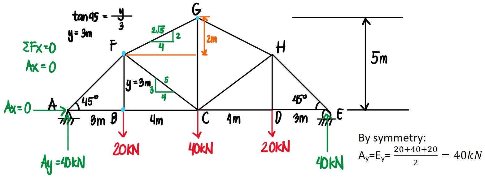
The truss is loaded as shown:
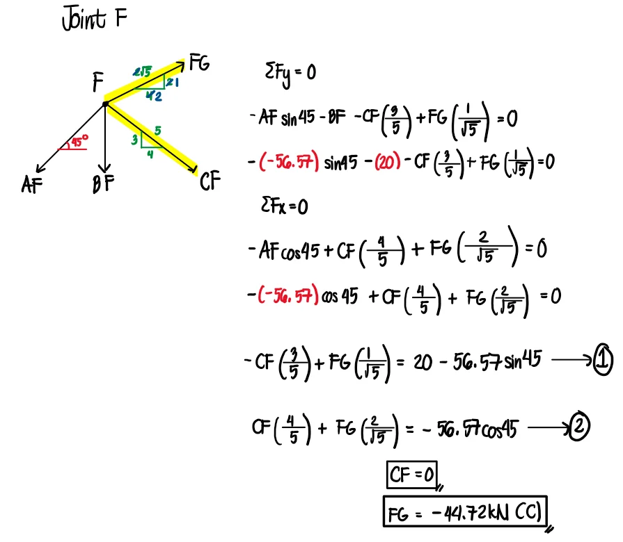
Compute the force in member AF (in kN).
56.57 (C)
56.57 (T)
44.72 (C)
44.72 (T)
Compute the force in member CF.
0
44.72 (T)
44.72 (C)
40 (T)
Compute the force in member FG.
44.72 (C)
44.72 (T)
56.57 (C)
56.57 (T)
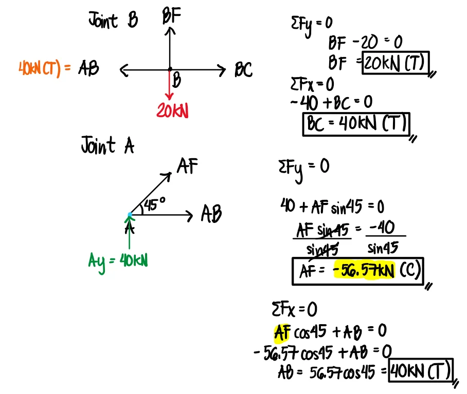
The reactions can be solved by taking advantage of the symmetry of the loading. For the reactions $A_y$ and $E_y$, we take the total vertical force and divide it by 2. We analyze joints A and B and determine the forces in the unknown members. We start at joint B and set the vertical forces equal to zero. Since only BF has a vertical internal force, we can directly equate it to the downward joint load at B. However, we cannot find yet the force in member AB and BC since these are two unknown horizontal internal forces.
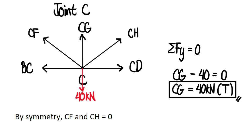
Hence, we proceed to joint A and solve AF and AB. Since there are only two unknowns on this joint, we can use $\Sigma F_x=0$ and $\Sigma F_y=0$ to solve the unknowns. Here, we use $\Sigma F_x=0$ and $\Sigma F_y=0$ to develop two equations with two unknowns. We then solve this using Mode 5-2 in our calculator. By symmetry, CF and CH are zero-force members. Therefore, $\Sigma F_y=0$ will give us the internal force in CG, which is 40kN (T).