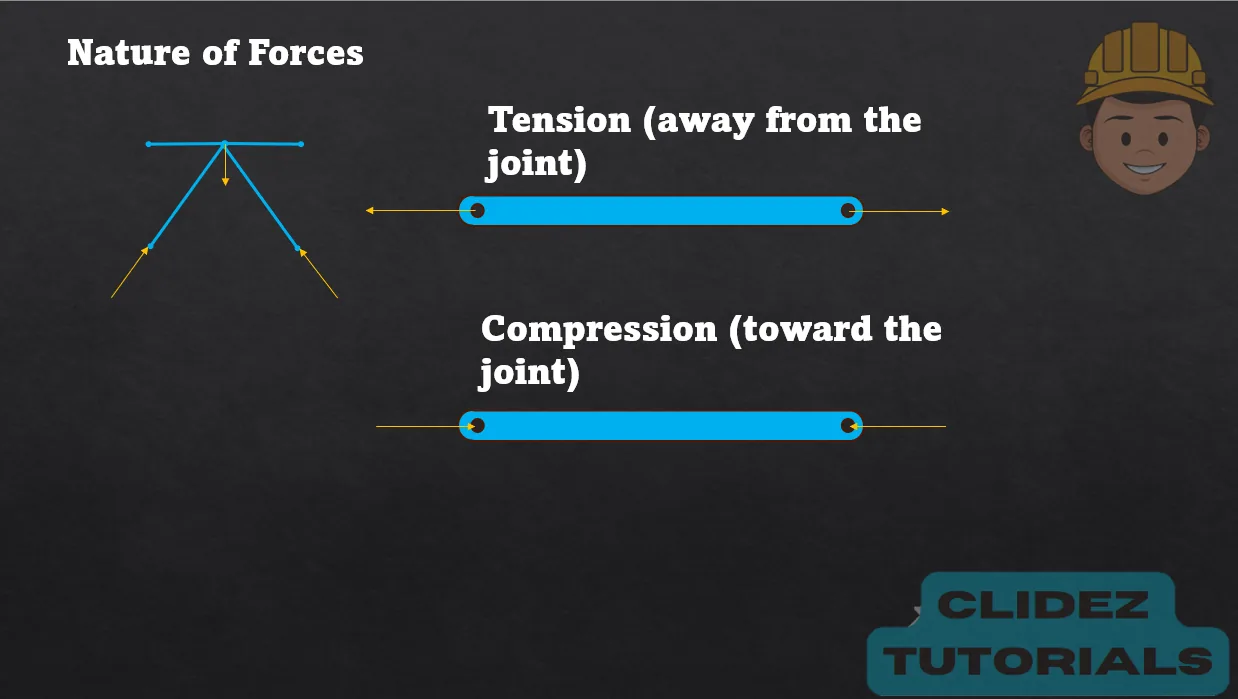
Analysis of Trusses (Joint Method)

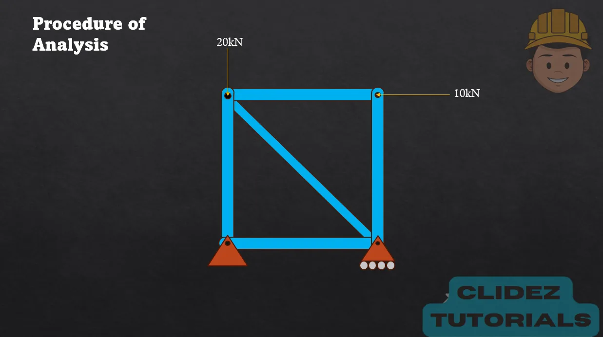
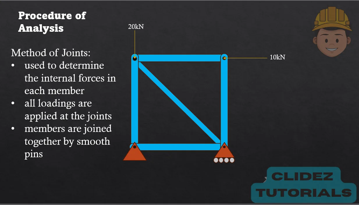
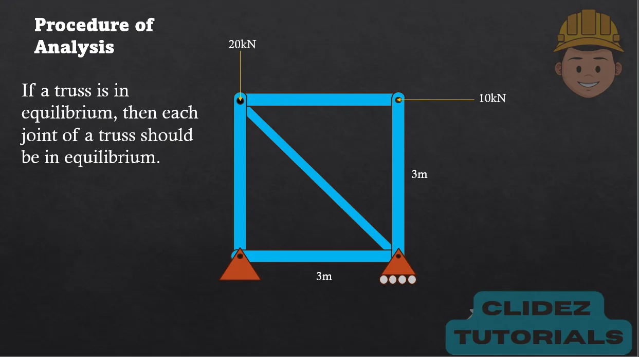
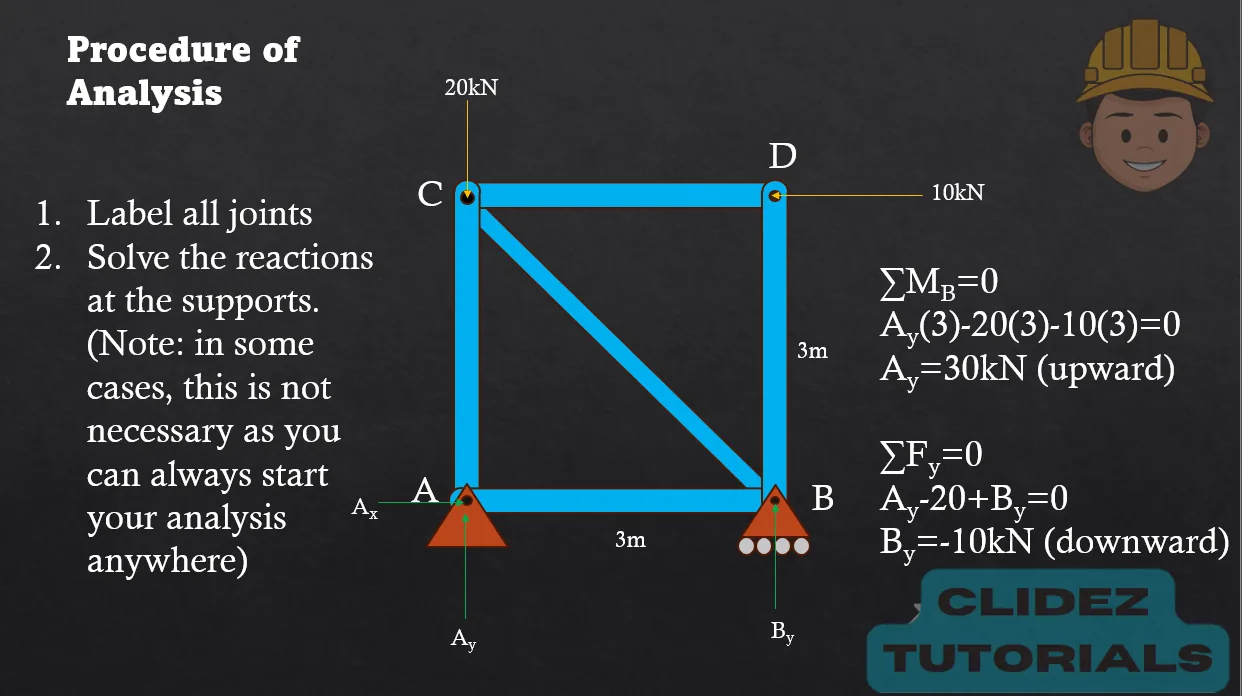
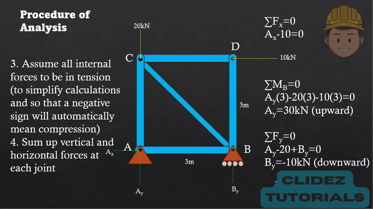

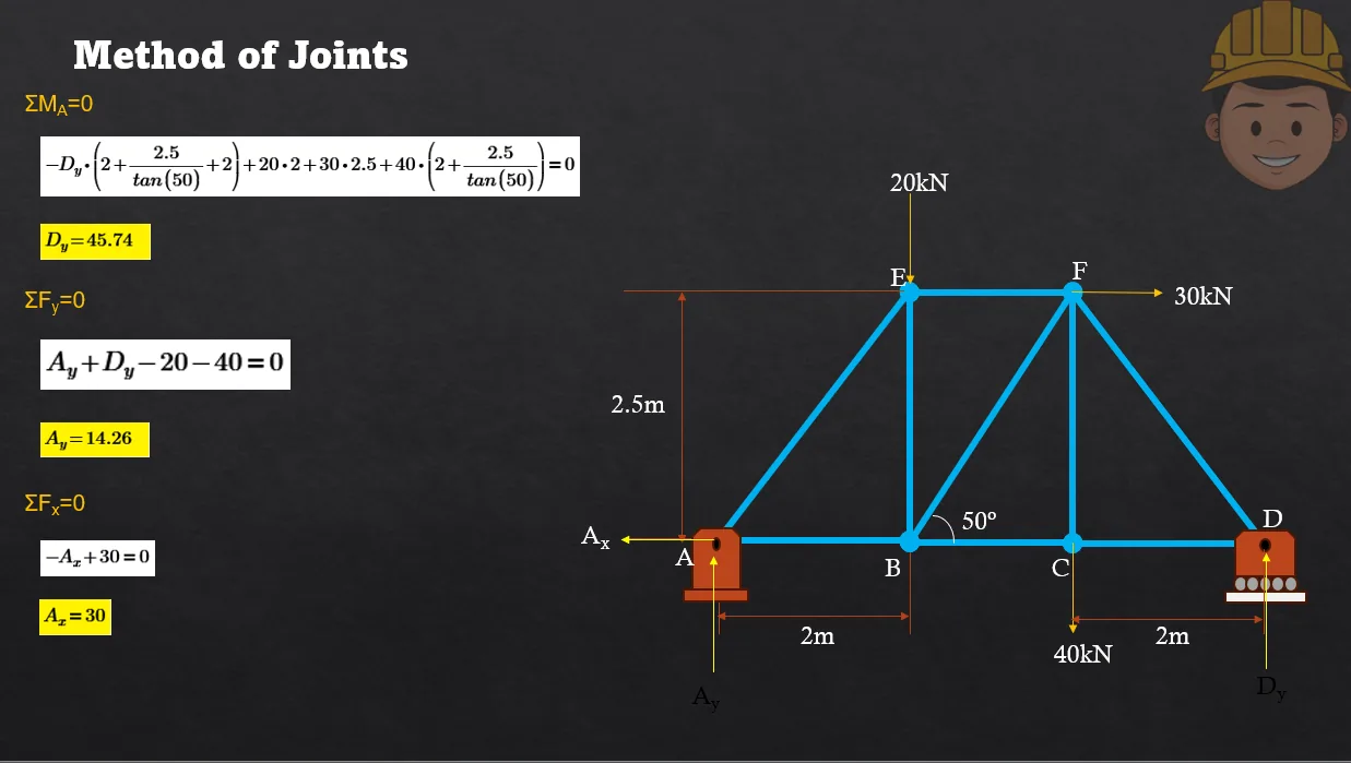
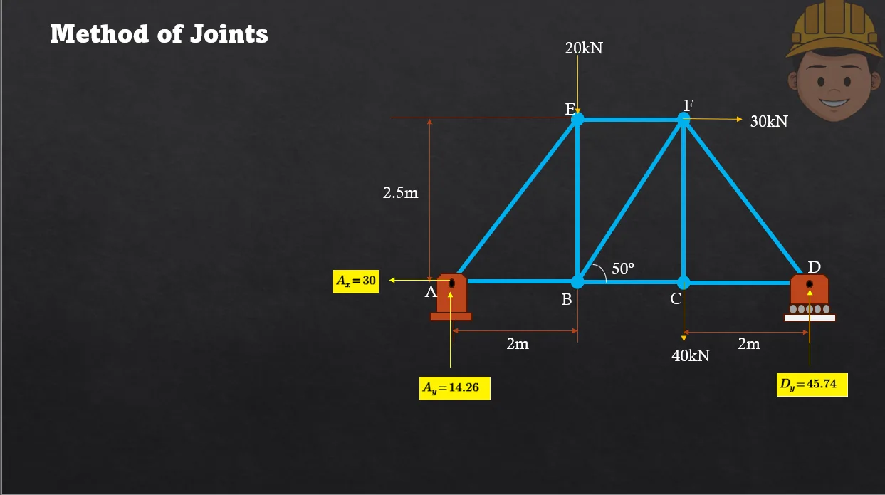
For the given truss, determine the forces in all members.


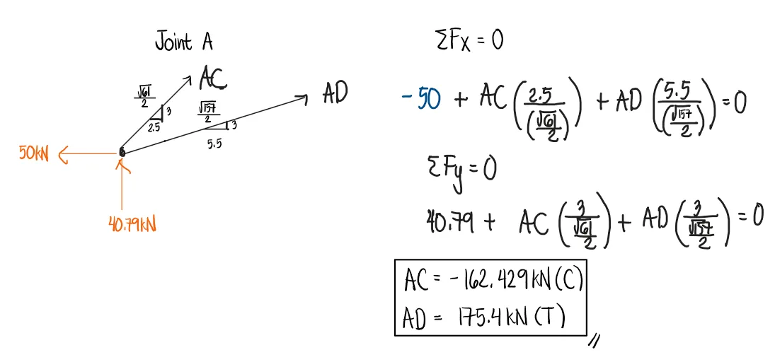
See images:
Refer to the image shown:


See images:
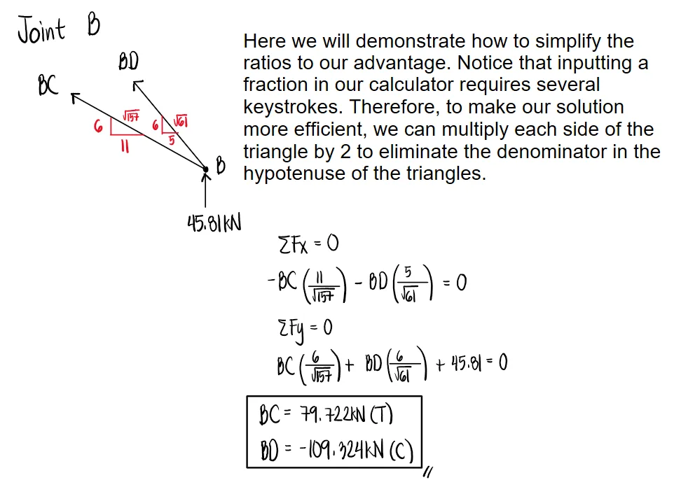
Refer to the image shown:


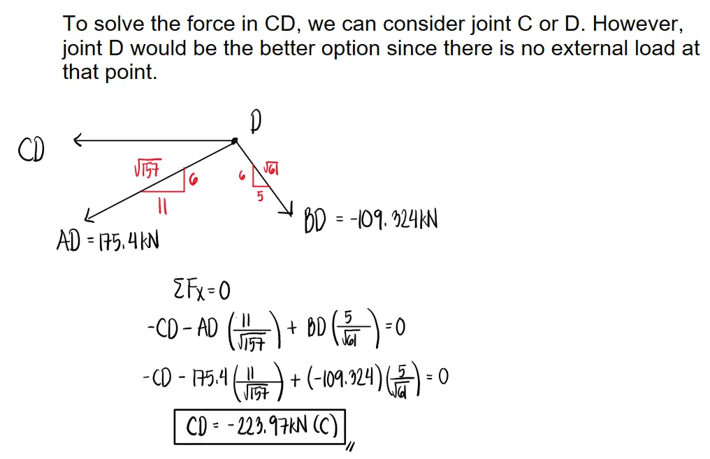
See images:


Refer to the image shown:


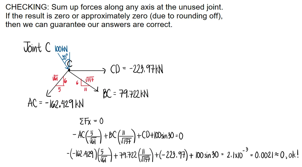
See images:


Refer to the image shown:


See images:


Refer to the image shown:


See images:


Refer to the image shown:


See images:


Refer to the image shown:


See images:


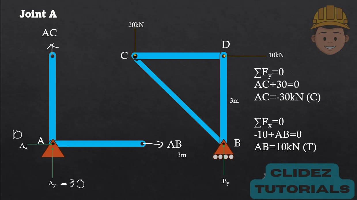
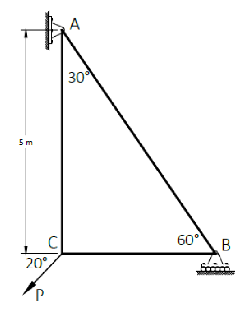
A triangular truss has supports at A and C, 6m apart, and joint B located 3m horizontally from A and 4m above AC. A 20kN downward load acts at B. Determine the forces in AB and BC.
The geometry of each inclined member is a 3-4-5 triangle. By symmetry, the vertical reactions are 10kN each.
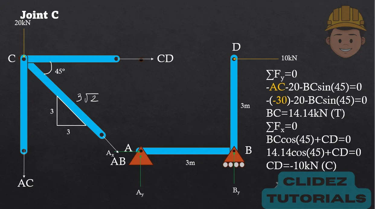
Using the same triangular truss, determine the force in member AC after finding that AB and BC are each 12.5kN in compression.
Use joint A. Member AB pushes joint A down-left because it is in compression.
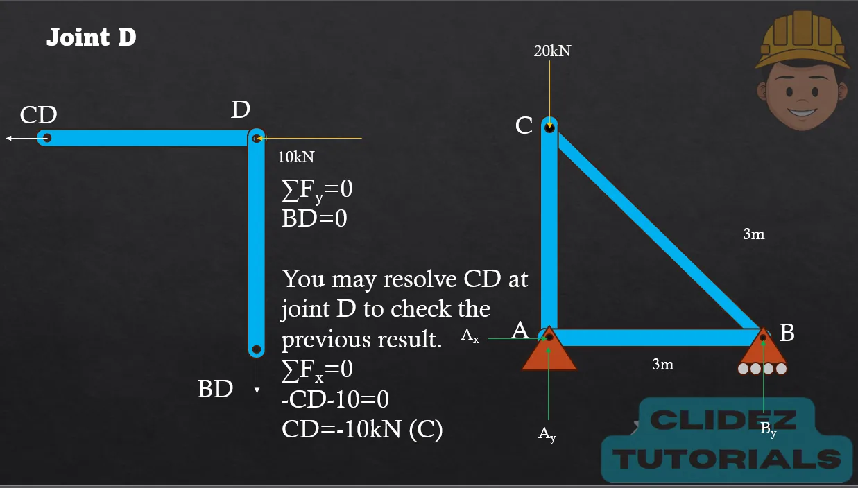
At a truss joint, member AB is horizontal to the left and member AC is inclined 30° above the horizontal to the right. A 6kN downward load and a 4kN horizontal load to the right act at the joint. Determine the member forces, assuming tension pulls away from the joint.
Analyze the loaded joint directly.
Additional board-style practice items for this topic.
For the truss shown below, the allowable forces for each member are the ff.
BC=70kN (T)
EC=60kN (C)
DE=25kN (C).
Compute the maximum safe value of P (in kN) if the strength of member EC governs.
Compute the maximum safe value of P (in kN) if the strength of member BC governs.
Compute the maximum safe value of P (in kN) if the strength of member DE governs.
Solution pending in psadquestions/q27.json.
For the truss shown,
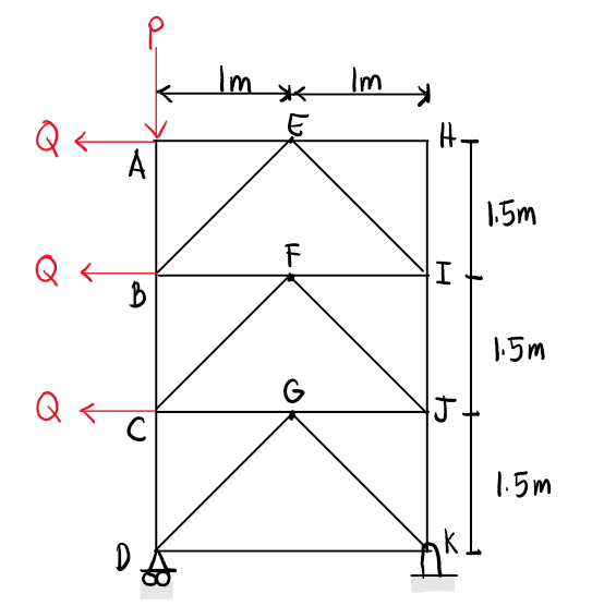
If P=3000N and Q=1000N, determine the force in member CD.
If P=3000N and Q=1000N, determine the force in member JK.
If FCD = 6000N and FGD= 1000N (both under compression), determine the value of P.
Solution pending in psadquestions/q53.json.
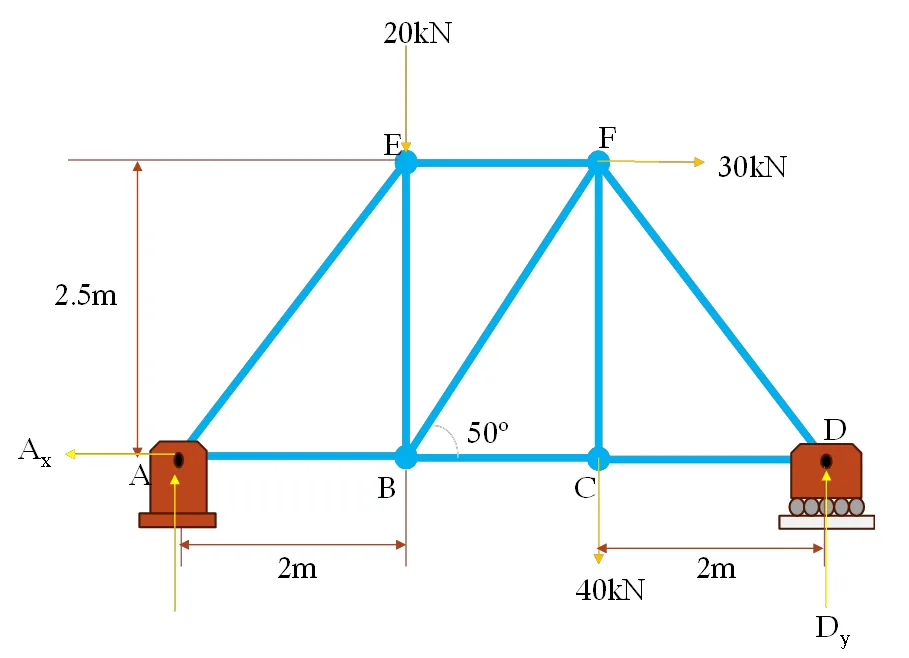
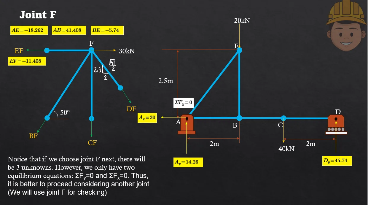
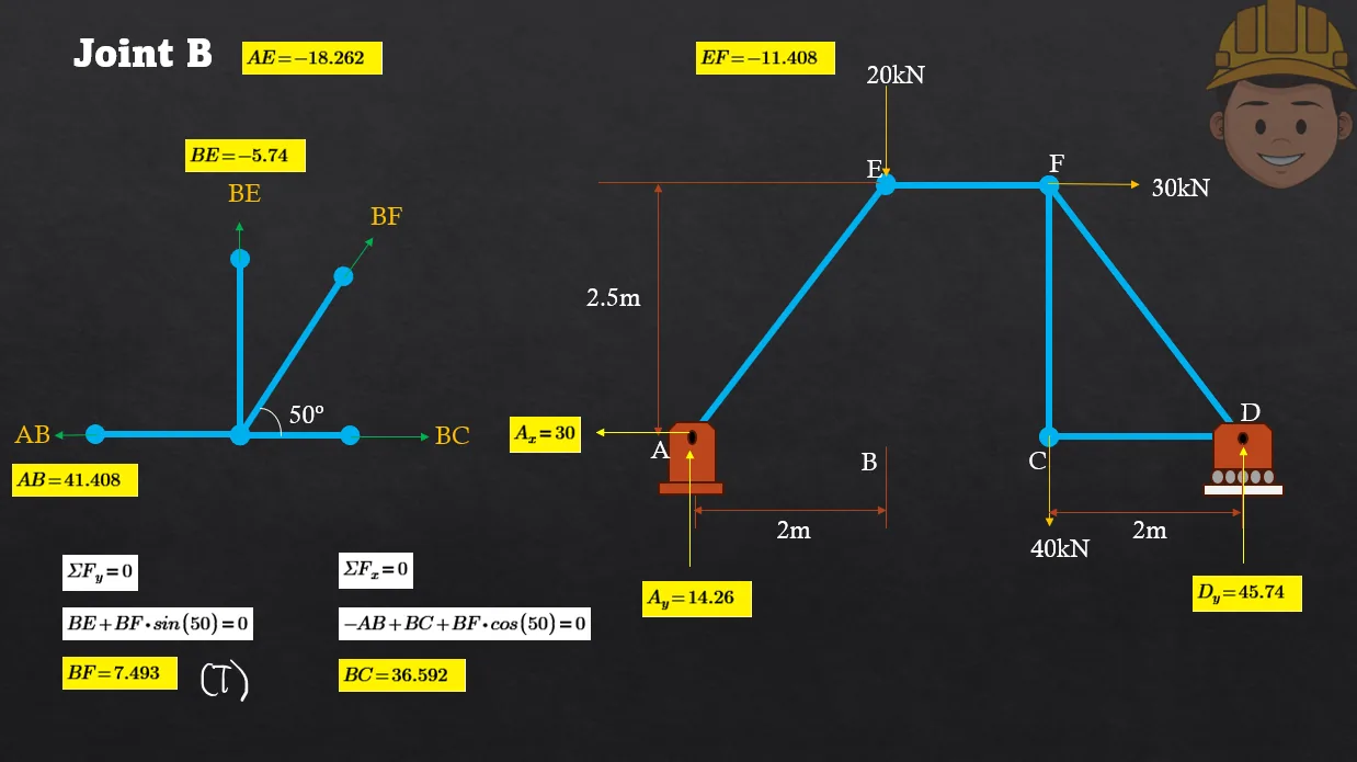
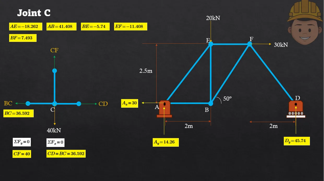
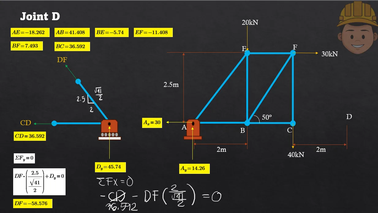
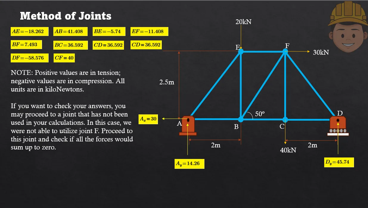
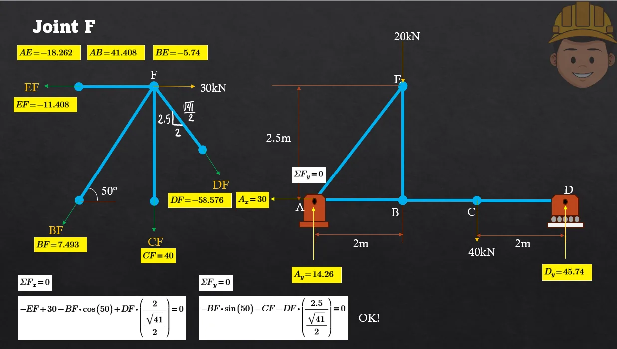
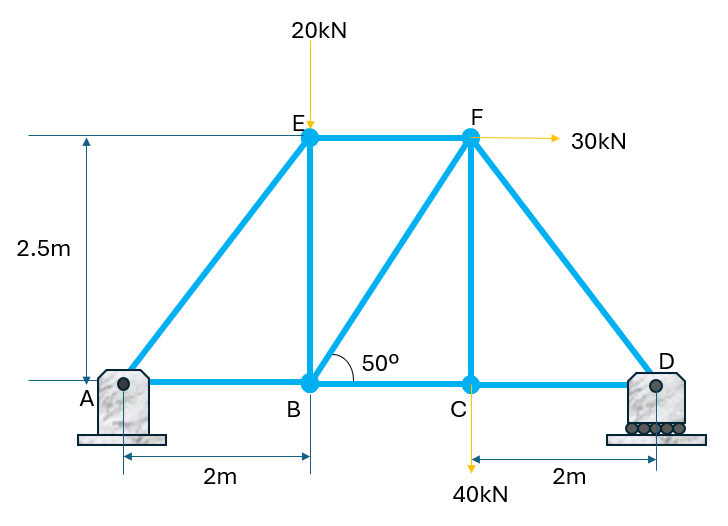
For the truss shown, determine the forces in all members by using the method of joints/sections.
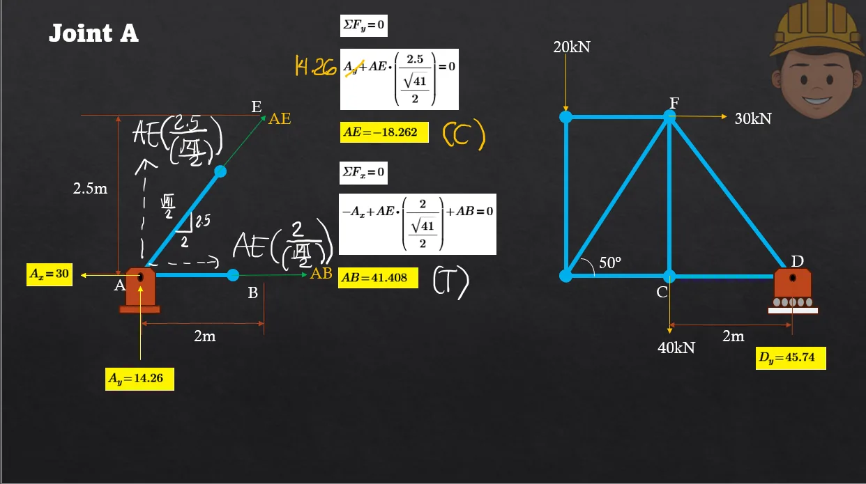
Force in AB
Force in AE
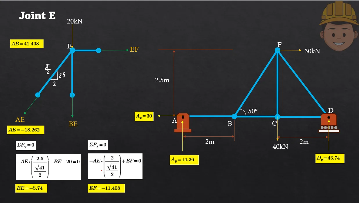
Force in BE
Force in EF
Force in BF
Force in BC
Force in CD
Force in DF
Force in CF
Solution pending in psadquestions/q324.json.
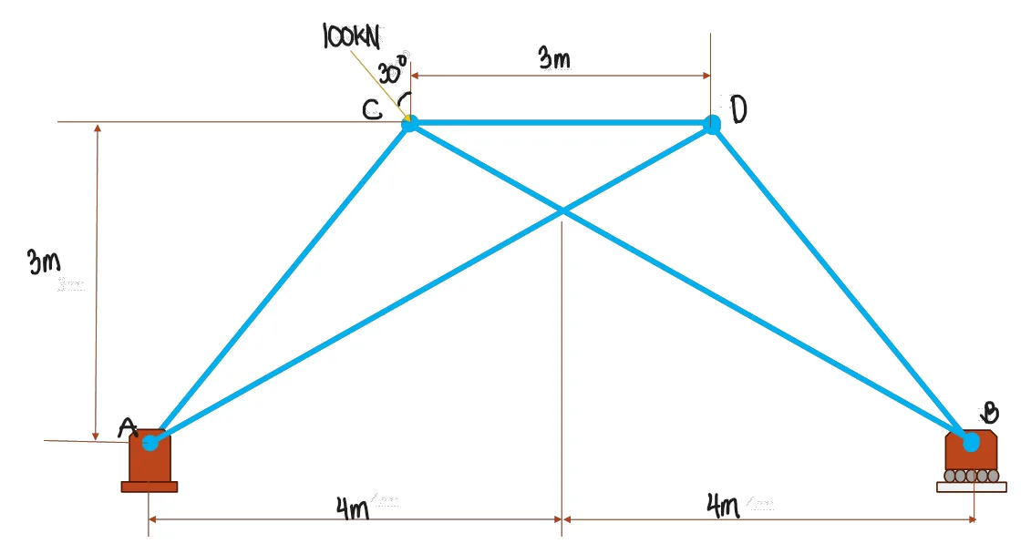
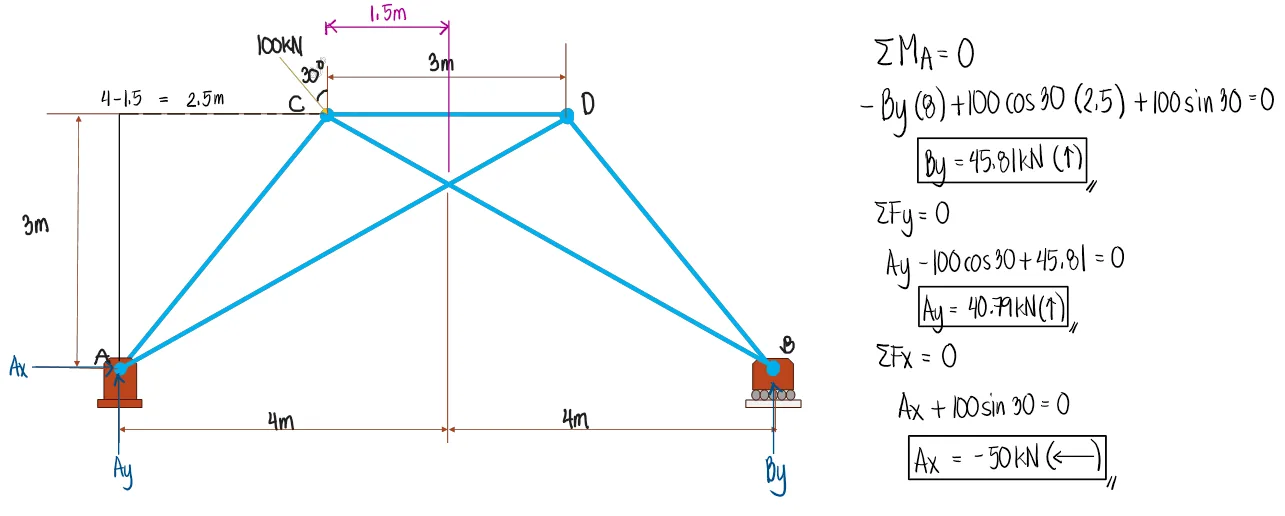
For the truss shown, if P=20kN
Determine the force of member AB in kN
Determine the force of member AC in kN
Solution pending in psadquestions/q423.json.
The truss shown is subjected to a lateral load of F=12kN.
a=1.5m
b=4m
c=3.5m
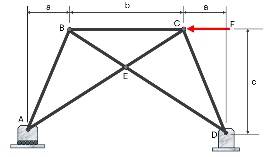
Determine the reaction at A in kN.
Determine the force in member AE, in kN.
Determine the reaction at D, in kN.
Solution pending in psadquestions/q615.json.
A transmission tower is loaded as shown.
P1=10kN
P2=13kN
P3=16kN
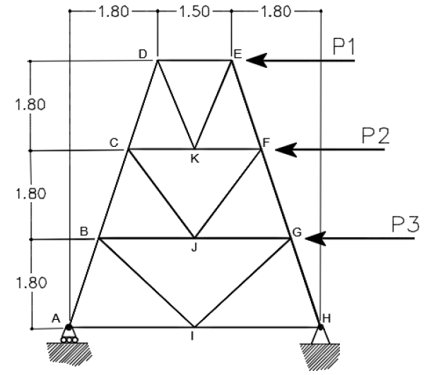
Determine the total reaction at H in kN.
Determine the force in member CJ, in kN.
Solution pending in psadquestions/q616.json.
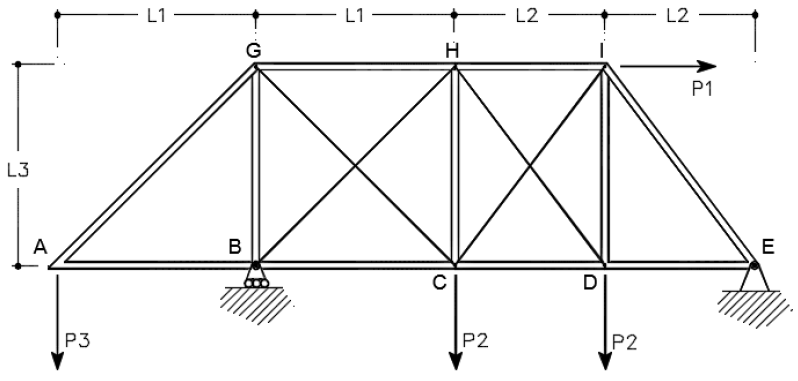
Refer to the figure shown. Diagonals BH, CG, HD, and CI are flexible cables and are, therefore, only capable of carrying tensile forces.
P1=2.5kN
P2=1.2kN
P3=1.2kN
L1=3m
L2=2.25m
L3=3m

Determine the force in member HD.
Determine the force in member CI.
What is the force in member BH?
What is the force in member CG?
Solution pending in psadquestions/q624.json.
Refer to the figure shown. Diagonals BH, CG, HD, and CI are flexible cables and are, therefore, only capable of carrying tensile forces.
P1=2.5kN
P2=0.0kN
P3=1.2kN
L1=3m
L2=2.25m
L3=3m
Determine the force in member CG, in kN.
Determine the force in member DH, in kN.
Determine the force in member DI, in kN.
Solution pending in psadquestions/q625.json.