Rotational Equilibrium: The sum of all moments about any point must also be zero
$$\sum M = 0$$
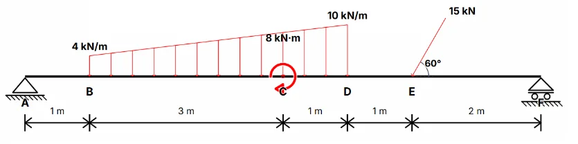
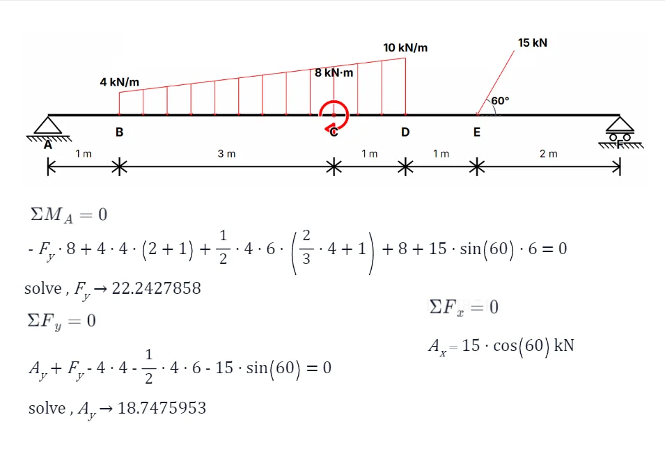
In engineering mechanics, a non-concurrent force system refers to a group of forces whose lines of action do not intersect at a single point. These forces may act on different parts of a rigid body and can include forces and moments (torques). To achieve equilibrium in such systems, a body must satisfy both conditions above.
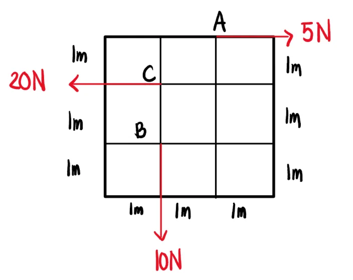
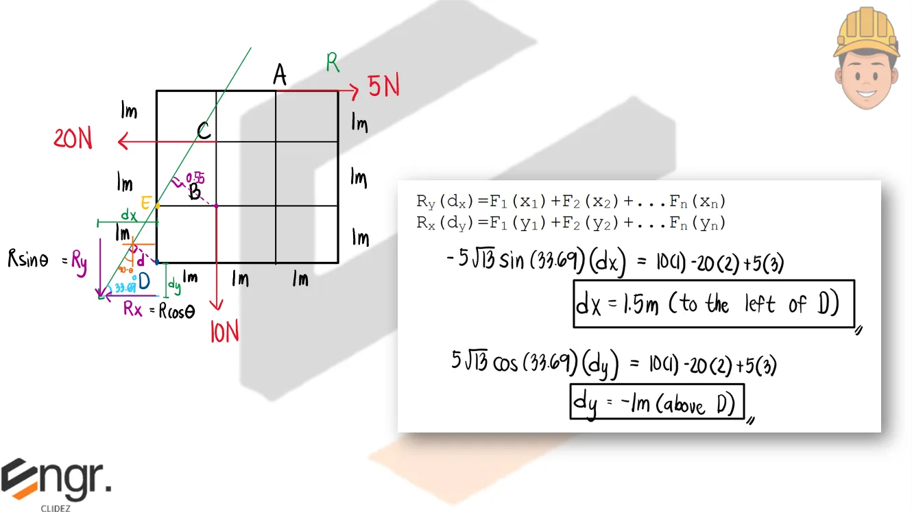
General Resultant of Non-concurrent Force Systems:
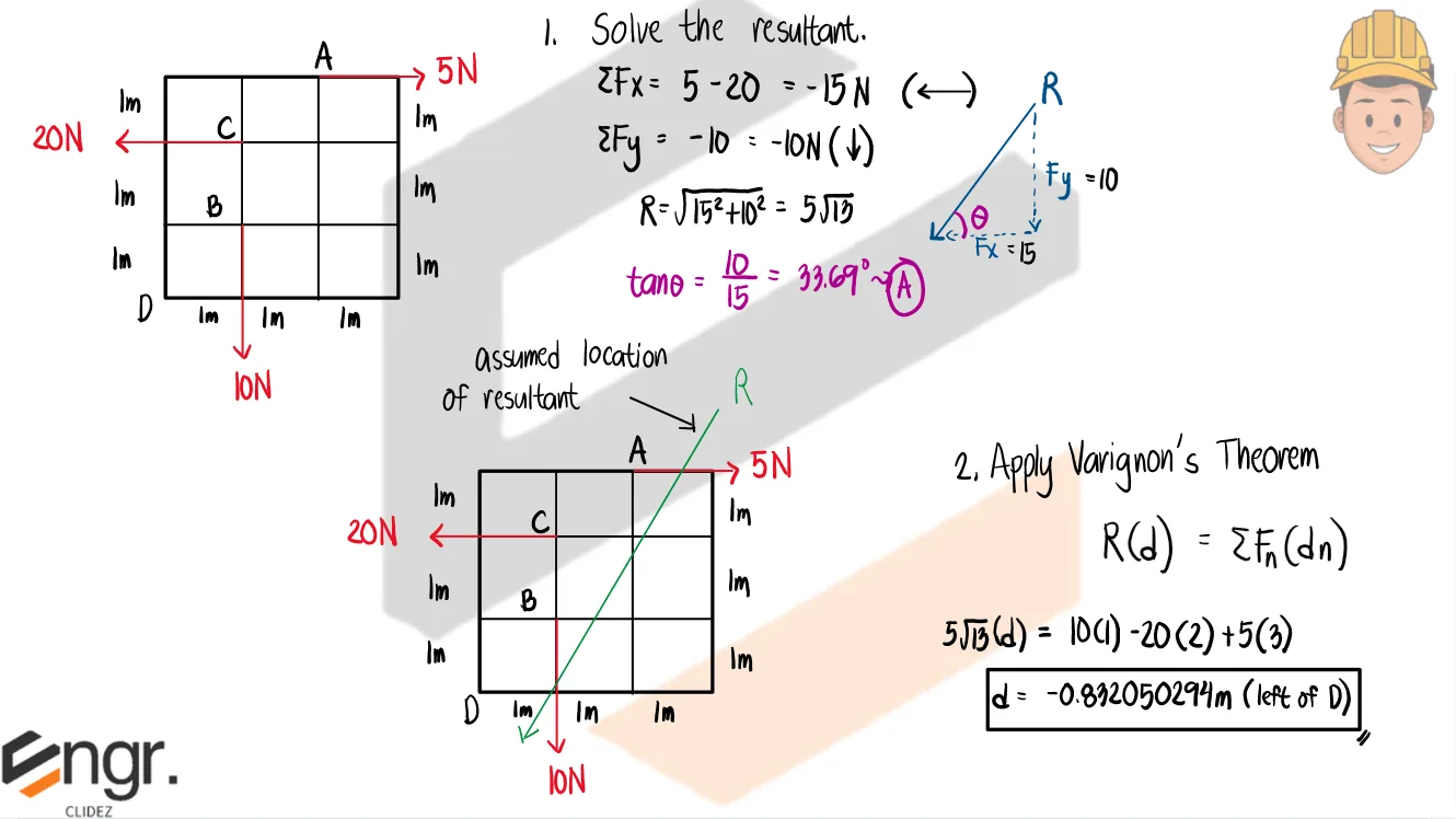
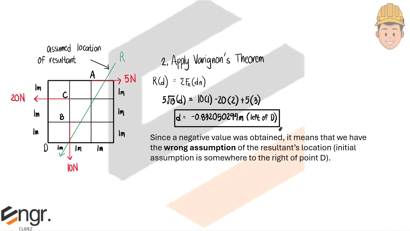
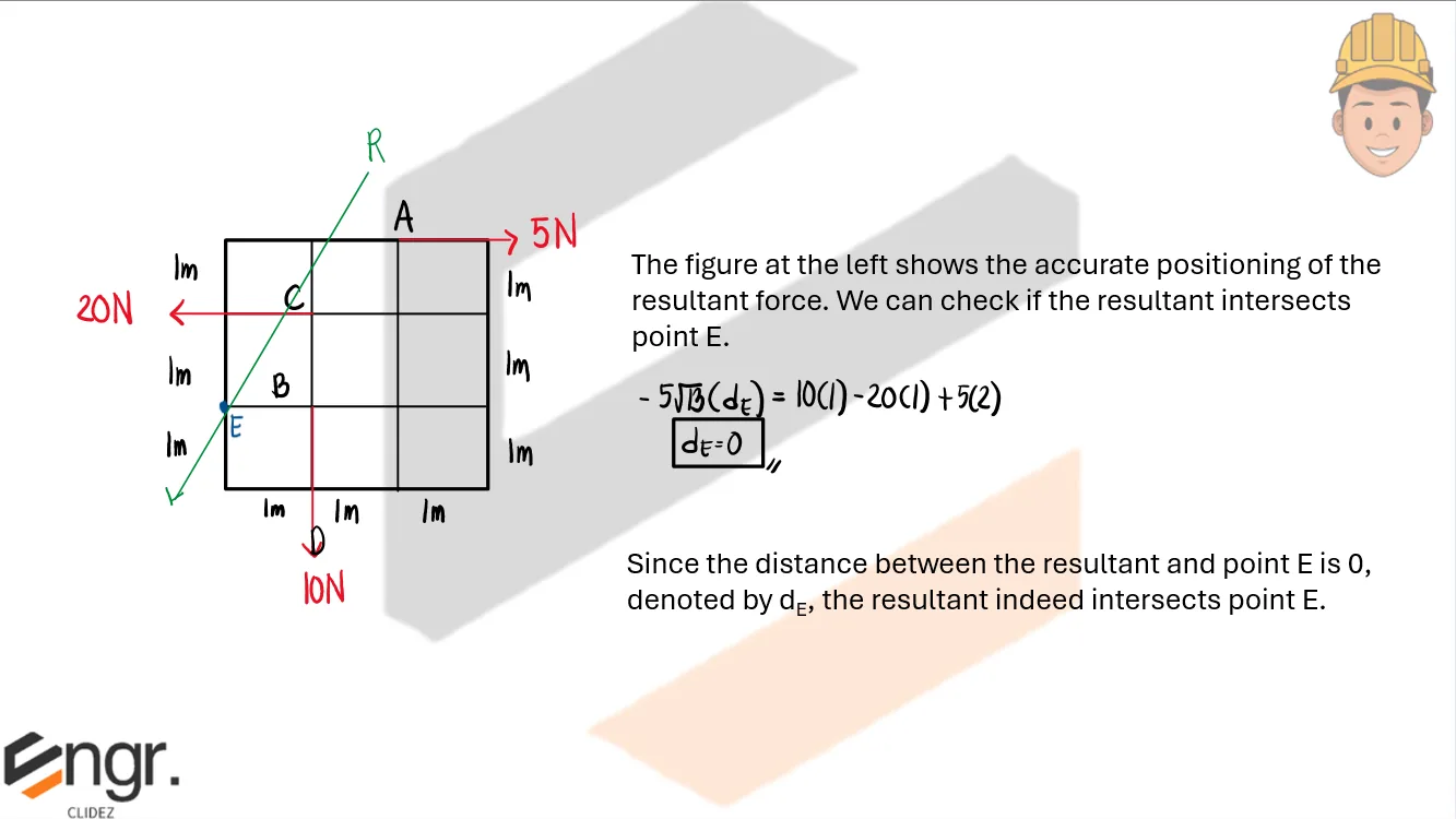
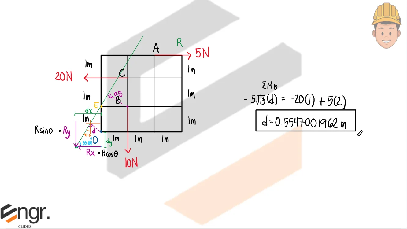
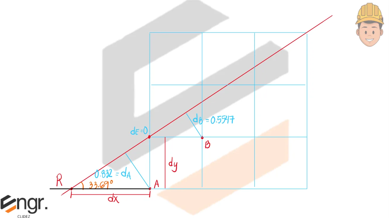
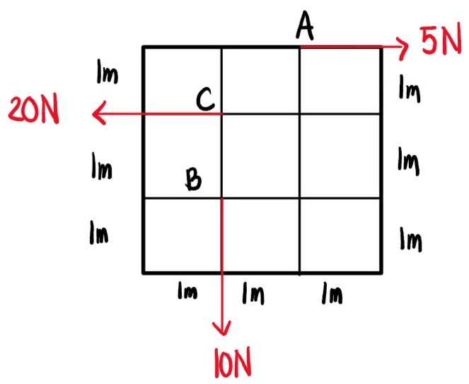
a. Calculate the location of the resultant from point D. b. Prove that the resultant force intersects point E (as indicated below) c. Determine the distance dx and dy from point D to the resultant force and indicate the location relative to D. d. Determine the distance from point B to the resultant force. e. Resolve the system into a resultant-couple system.
See images:
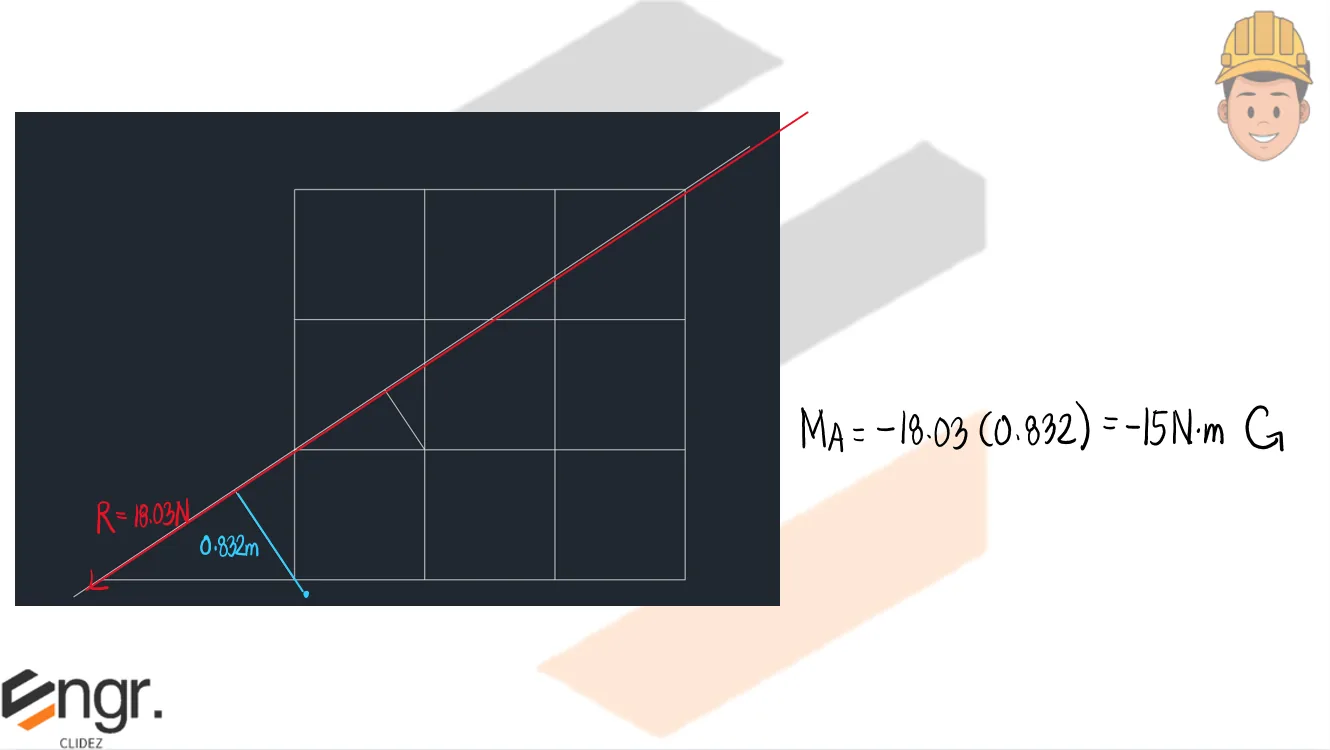
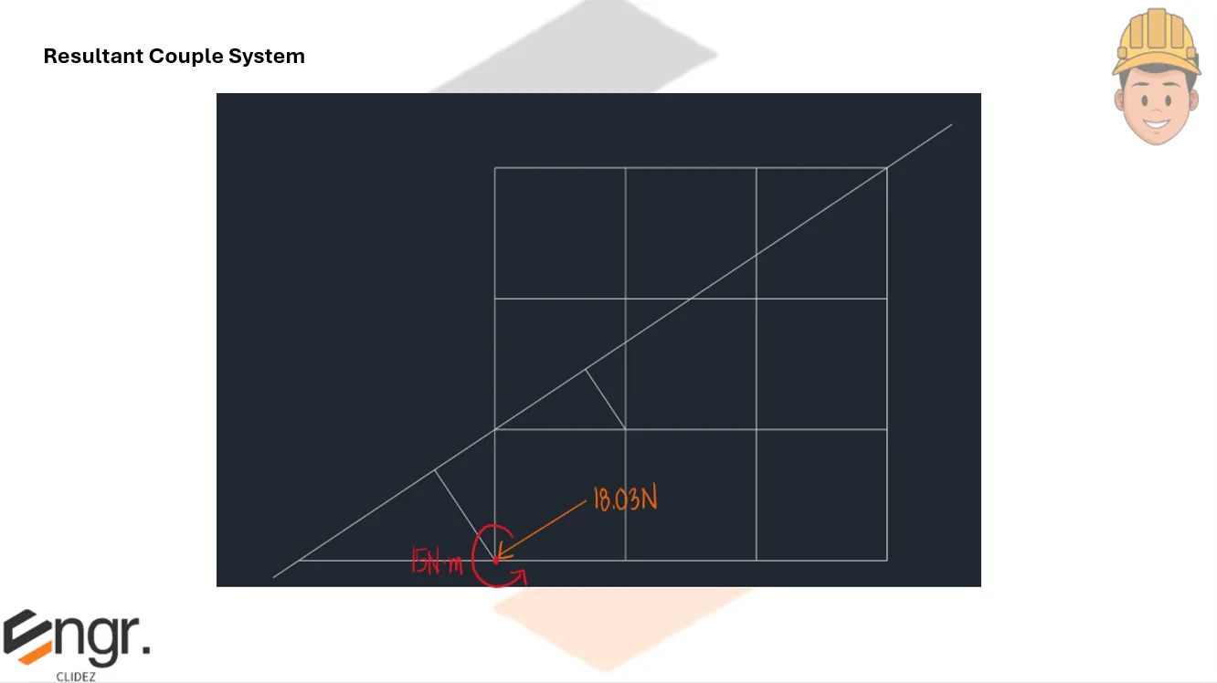
Below is a scaled drawing of the figure (modeled using AutoCad).We can obtain the moment caused by the resultant force about point D so that we can transfer the resultant so that it intersects point D. The moment (couple) will be applied at point D for clarity. Finally, we have this resultant-couple system that replaces the system above.
Problem:
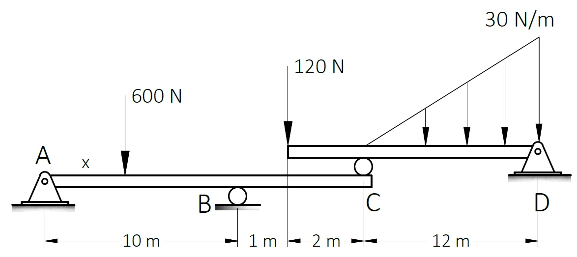
For the beam shown, beam ABC is supporting beam CD.
Which of the following most nearly gives the reaction at C in kN.
A. 250
B. 150
C. 100
D. 200
Which of the following most nearly gives the reaction at D in kN.
A. 250
B. 150
C. 100
D. 200
Which of the following most nearly gives the value of "x" if the reaction at B is 380 N.
A. 1
B. 1.5
C. 2
D. 3
See images:
Problem:
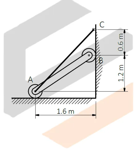
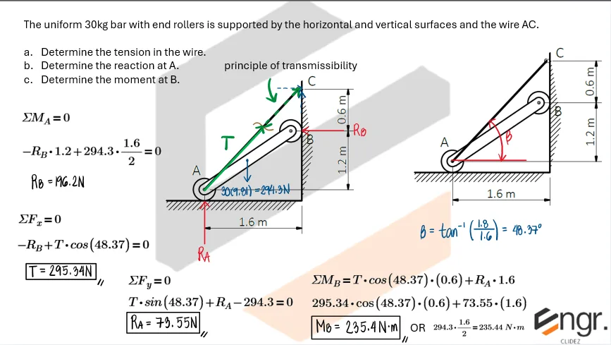
The uniform 30kg bar with end rollers is supported by the horizontal and vertical surfaces and the wire AC.
a. Determine the tension in the wire.
b. Determine the reaction at A.
c. Determine the moment at B.
See images:
Problem:
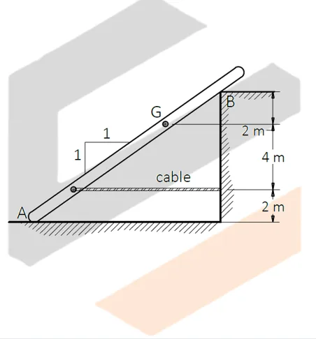
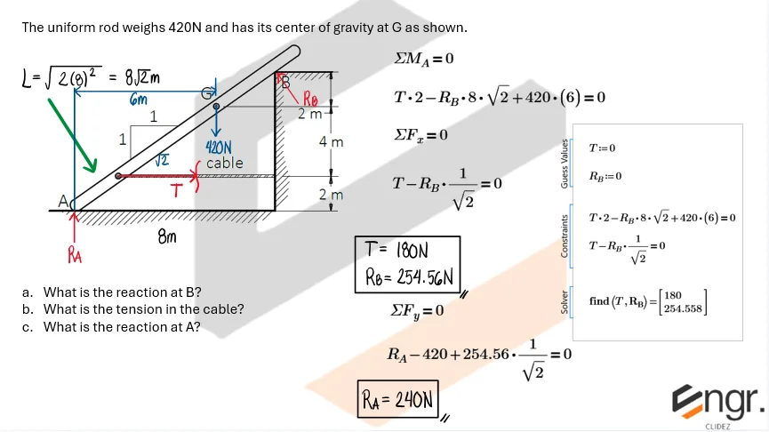
The uniform rod weighs 420N and has its center of gravity at G as shown.
a. What is the reaction at B?
b. What is the tension in the cable?
c. What is the reaction at A?
See images:
Problem:
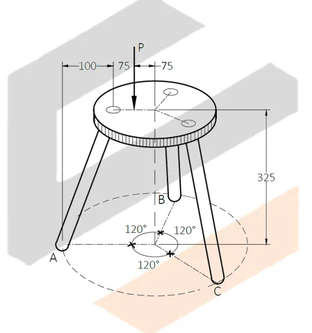
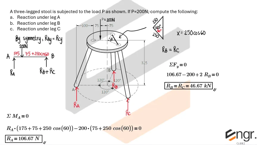
A three-legged stool is subjected to the load P as shown. If P=200N, compute the following:
a. Reaction under leg A
b. Reaction under leg B
c. Reaction under leg C
See images:
Problem:
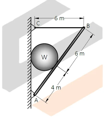
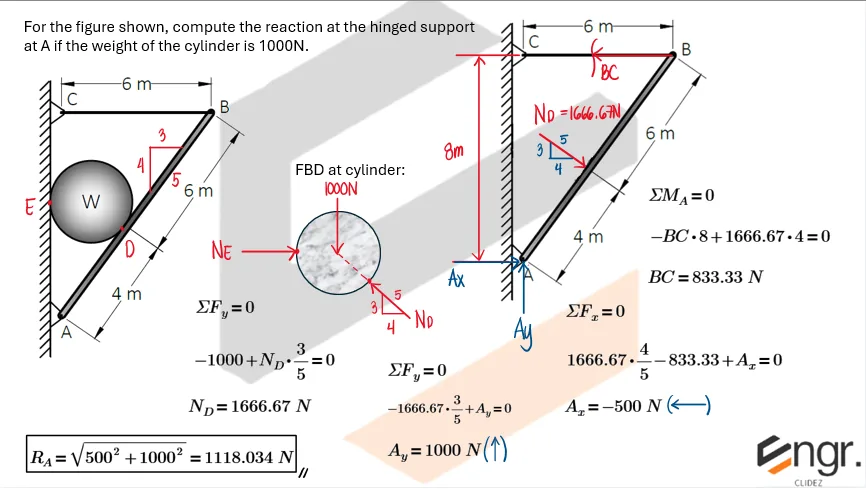
For the figure shown, compute the reaction at the hinged support at A if the weight of the cylinder is 1000N.
See images:
Problem:
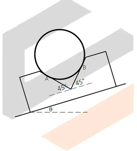
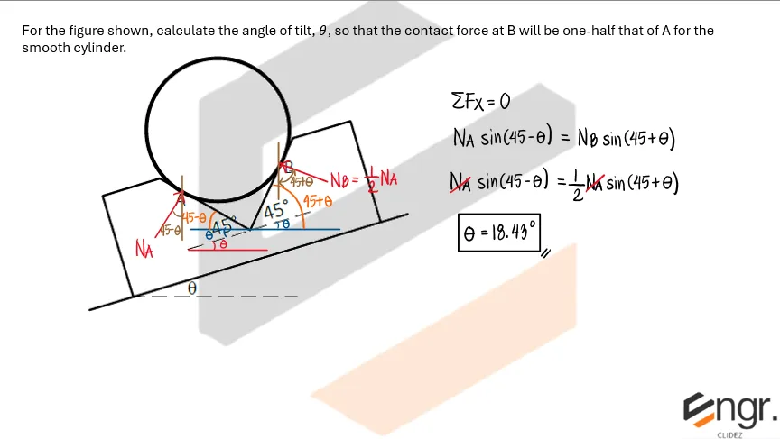
For the figure shown, calculate the angle of tilt, θ, so that the contact force at B will be one-half that of A for the smooth cylinder.
See images:
Problem: Walkway from a Pier to a Float
To accomodate the rise and fall of tide, a walkway from a pier to a float is supported by two rollers as shown. The center of mass of the 300-kg walkway is at G.
a. Calculate the force under the roller at A in Newtons.
b. Calculate the tension T in the horizontal cable which is attached to the cleat in Newtons.
c. Calculate the force in the roller at B in Newtons.
See images:
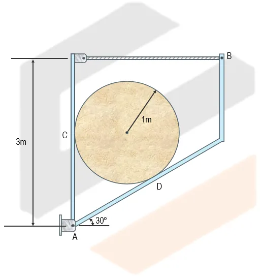
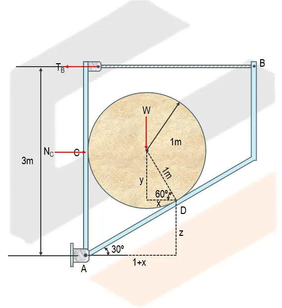
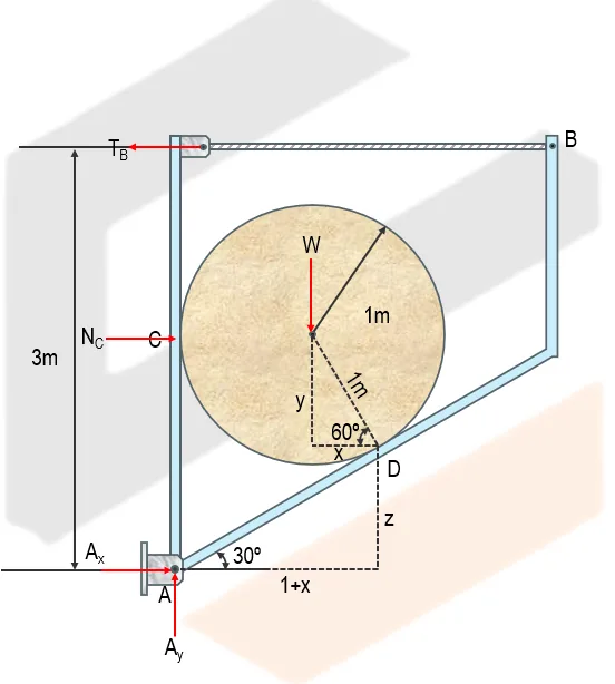
Problem: Cylinder Placed between a Rigid Member
The cylinder below has a mass of 200kg. Determine the following:
a. The normal reaction at D in Newtons.
b. The normal reaction at the wall at C in Newtons.
c. The tension in the cable at D in Newtons.
See images:
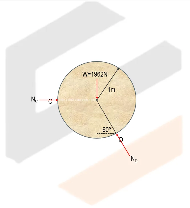
FBD of cylinder
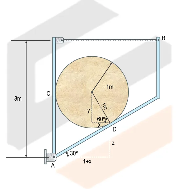
$$
W = 200(9.81) = 1962\ \text{N}, \qquad r = 1\ \text{m}, \qquad h = 3\ \text{m}
$$
$$
\theta = 30^\circ, \qquad a = 90^\circ - 30^\circ = 60^\circ
$$
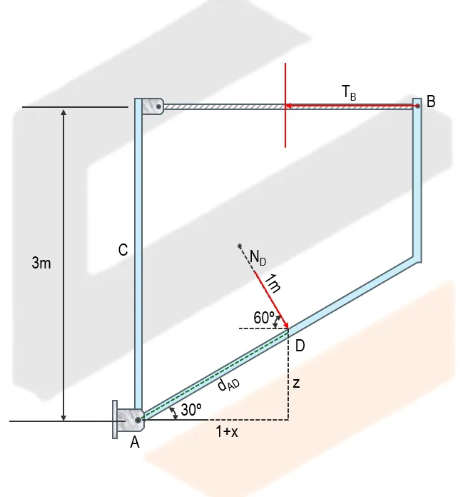
All moment equations are taken about point A, the hinge support, so the unknown hinge reactions at A are eliminated. The normal reaction used depends on the chosen FBD: the FBD considering the contact at D uses $N_D$ and does not include $N_C$, while the external FBD uses the normal reaction at C and does not include $N_D$. Since $N_D$ is the resultant effect of the cylinder's weight $W$ and the wall reaction $N_C$, $N_C$ is not written separately when $N_D$ is already being considered.
A 5m simply supported beam has a 10kN force applied at midspan, inclined 30° from the vertical toward the right. Determine the support reactions if A is a pin and B is a roller.
Resolve the inclined force first. The roller at B has only a vertical reaction.
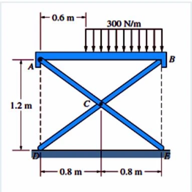
The folding table is loaded as shown:
a. Compute the reaction (N) at E.
b. Compute the reaction (N) at the pin at A.
c. Compute the reaction (N) at the pin at C.
Folding Table: Reactions at E, A, and C
Given
The table width is
$$
AB = DE = 0.8 + 0.8 = 1.6\text{ m}
$$
The uniformly distributed load is
$$
w = 300\text{ N/m}
$$
The load starts $0.6\text{ m}$ from point $A$ and extends to point $B$.
Therefore, the loaded length is
$$
L = 1.6 - 0.6 = 1.0\text{ m}
$$
Equivalent Concentrated Load
Replace the distributed load with an equivalent concentrated load.
$$
W = wL
$$
$$
W = 300(1.0)
$$
$$
W = 300\text{ N}
$$
The equivalent load acts at the center of the loaded length. Its
distance from point $A$ is
Additional board-style practice items for this topic.
Question Bank: longquiz20
PSAD - Statics / Equilibrium of Rigid Bodies / Engr. Anne
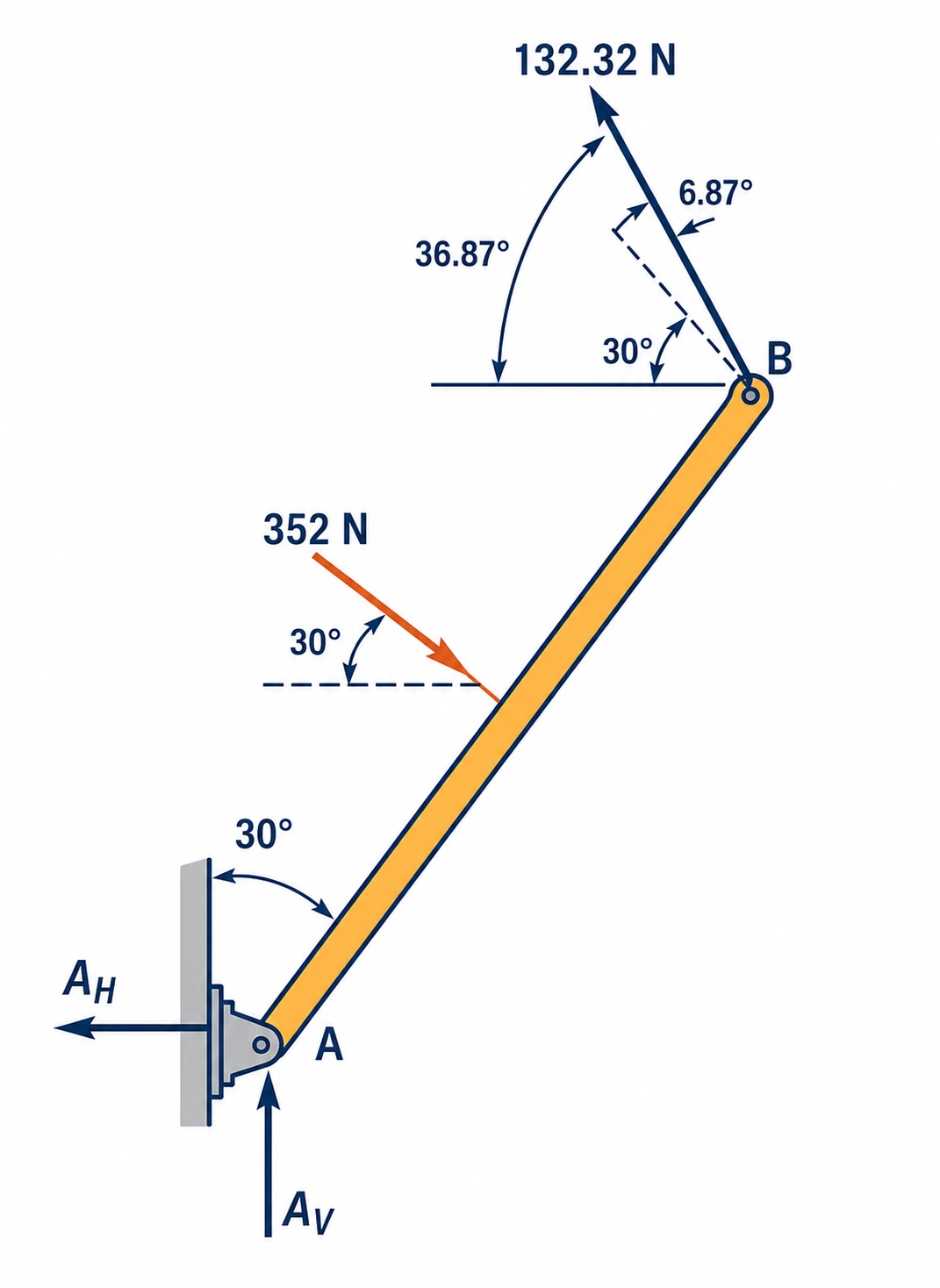
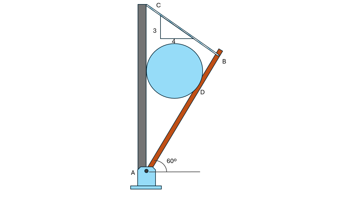
A 10 m rod is connected to a pin at A and to a chord at B as shown. The rod is inclined 30° from the vertical wall and holds a cylindrical drum weighing 176 N. The drum has a diameter of 2 m. The chord BC runs from the top of the rod to the wall on a 3:4 slope.
Which of the following gives the force between the drum and the rod?
352 N
176 N
203 N
305 N
Which of the following gives the force in the chord BC?
132.32 N
176.00 N
96.61 N
221.19 N
Which of the following gives the reaction at the pin at A?
221.19 N
198.94 N
176.00 N
132.32 N
Force between the drum and the rod: The reaction $R_2$ from the rod on the drum is perpendicular to the rod, i.e. $60^\circ$ from the vertical. $\sum F_v=0:\;R_2\cos60^\circ=176$ $\boxed{R_2=352\text{ N}}$
Force in the chord BC: The line of action of $R_2$ meets the rod at D, where $\tan15^\circ=\dfrac{1}{AD}\;\Rightarrow\;AD=3.732\text{ m}$ The chord slope 3:4 gives $\tan\theta=\dfrac{3}{4}\;\Rightarrow\;\theta=36.87^\circ$, so the chord makes $6.87^\circ$ with the normal to the rod. $\sum M_A=0:\;352(3.732)=T\cos6.87^\circ(10)$ $\boxed{T=132.32\text{ N}}$
PSAD - Statics / Equilibrium of Nonconcurrent Force Systems / Engr. Janclyde Espinosa (Clidez)
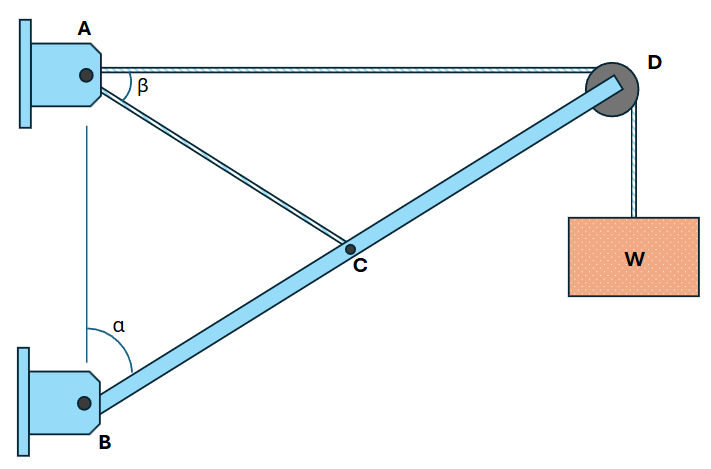
A boom supports a 100N load. If the tension in the cable is 200N,
Determine the angle α (in degrees)
21.47
20.92
23.45
19.87
Determine the angle θ (in degrees)
42.94
41.84
46.9
39.74
Determine the force in the boom in Newtons.
254.26 (C)
254.26 (T)
264.52 (C)
264.52 (T)
Part 1.
Let the boom force be $C$. At the top joint, the 200-N cable force, the 100-N load, and the boom force are in equilibrium. With $\theta=2\alpha$,
$C\cos(2\alpha)=200\cos\alpha$
$C\sin(2\alpha)=100+200\sin\alpha$
Dividing the equations and solving gives $\alpha=21.47^\circ$.
Part 2. $\theta=2\alpha=2(21.47^\circ)=\boxed{42.94^\circ}$.
Part 3. Substitute $\alpha=21.47^\circ$ in the horizontal equilibrium equation:
$C=\dfrac{200\cos21.47^\circ}{\cos42.94^\circ}=\boxed{254.26\text{ N (compression)}}$.
Question Bank: q3
PSAD - Statics / Equilibrium of Nonconcurrent Force Systems / Engr. Janclyde Espinosa (Clidez)
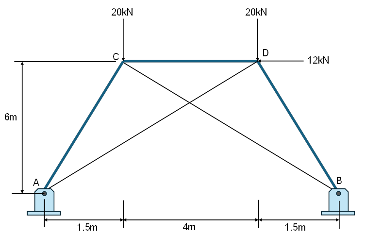
CE Board Nov. 2024 For the truss shown, members AD and BC are flexible cables.
Calculate the vertical reaction (kN) at A.
30.286
31.218
20.616
42.333
Calculate the force in member AC (kN).
31.218 (C)
31.218 (T)
42.333 (C)
42.333 (T)
Calculate the force in member BD (kN).
20.616 (C)
30.386 (C)
30.386 (T)
20.616 (T)
The diagonals AD and BC are flexible cables, so a trial solution that puts either cable in compression is not admissible; that cable is released (zero force). Use the remaining members and the joint equations.
Part 1. From whole-truss equilibrium, $\sum M_A=0$ and $\sum F_y=0$ give the support reactions. The vertical reaction at A is $A_y=\boxed{30.286\text{ kN}}$.
Part 2. At joint C, resolve the force in AC using its direction ratios $1.5:6$. The joint equations give $F_{AC}=\boxed{31.218\text{ kN (compression)}}$.
Part 3. Apply the same joint equilibrium at D, using the $1.5:6$ geometry of member BD. This gives $F_{BD}=\boxed{20.616\text{ kN (compression)}}$.
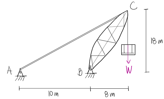
A load W = 20kN is to be lifted using the crane which is hinged at B as shown. Neglect the weight of the crane.
Determine the force in cable AC (in kN)
22.627
19.618
24.879
29.6
Determine the resultant reaction at B (in kN)
39.4
46.78
23.43
27.9
Determine the largest load W the can be lifted if the maximum force of cable AC is 50kN.
44.194
56.78
30.16
23.27
The cable AC has a 45-degree line of action because its horizontal and vertical projections are both 18 m. Take moments about B.
Part 1. $\sum M_B=0$:
$T_{AC}[18\sin45^\circ-8\sin45^\circ]-20(8)=0$
$T_{AC}=\boxed{22.627\text{ kN}}$.
Part 2. From force equilibrium,
$B_x=T_{AC}\cos45^\circ=16.0\text{ kN}$ and $B_y=20+T_{AC}\sin45^\circ=36.0\text{ kN}$.
$R_B=\sqrt{16^2+36^2}=\boxed{39.4\text{ kN}}$.
Part 3. The moment equation is linear in W, so $W_{\max}=20(50/22.627)=\boxed{44.194\text{ kN}}$.
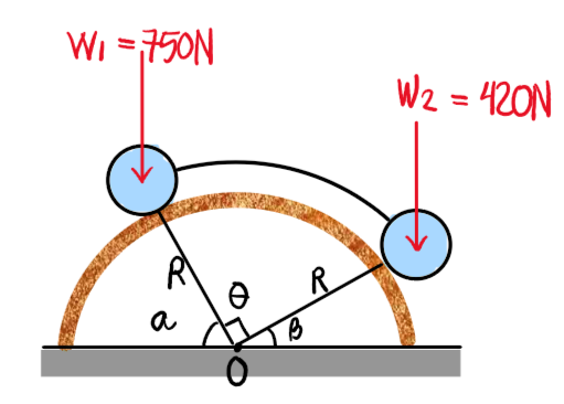
CE Board November 2024 Two cylinders are loaded as shown and are connected by a rigid curved rod parallel to the smooth cylindrical surface. Neglect the diameter of the cylinders. W1=750N, W2=420N ϴ=90º, R=6m
If the surfaces are frictionless, what is α to maintain equilibrium?
60.75
50.17
45.14
76.12
If the coefficient of friction is μs=0.2 in the contacting surfaces, what is α to prevent rotation counterclockwise?
38.66
56.88
49.44
50.17
If the coefficient of friction is μs=0.015 in the contacting surfaces, which of the following gives α to impend motion?
59.15
47.15
34.34
62.34
Draw separate free-body diagrams of the two cylinders. At each contact, the normal reaction is radial; when friction is present, the limiting friction is $F=\mu_sN$ and acts tangent to the cylindrical surface. The curved link is a two-force member, so its end forces are along the link.
Part 1. With smooth surfaces, set the two radial-normal-force moment equations about O to zero. The equilibrium angle is $\boxed{\alpha=60.75^\circ}$.
Part 2. For impending counterclockwise rotation, introduce $F=0.2N$ in the resisting tangential directions. Solving the limiting-equilibrium equations gives $\boxed{\alpha=38.66^\circ}$.
Part 3. Repeat with $F=0.015N$ and reverse the friction directions for impending motion. The limiting angle is $\boxed{\alpha=59.15^\circ}$.
For the assembly shown, beam AB weighs 100lbs. It is loaded with a force P=200lbs. A frictionless pulley with radius "r" weighs 80lbs and is attached at the end of the beam at point B, supported by two ropes inclined at angles x and y at points C and D. If a=2ft, b=3ft, angles x & y are 30º and 40º, respectively, and r=6 in.,
CE Board Nov 2011 and April 2025 A load W=30kN is lifted by a boom BCD making an angle, α=60º from the vertical axis as shown. Neglect the weight of the boom.
Determine the angle β between the cables AC and AD, in degrees. Note: Point C is midway points B and D.
30
35
25
20
Compute the tension in cable AC, in kN.
25.36
43.92
25.98
34.92
Determine the reaction at B in kN.
54.77
51.96
58.09
53.49
The boom makes $\alpha=60^\circ$ from the vertical, or 30 degrees from horizontal. Since C is the midpoint of BD and A is level with D, the geometry of AC gives $\beta=\boxed{30^\circ}$.
Part 2. At D, the pulley transmits 30 kN left and 30 kN down. Taking moments about B for the boom gives
$T_{AC}[0.433L]-30L(0.866-0.5)=0$,
so $T_{AC}=\boxed{25.36\text{ kN}}$.
Part 3. From $\sum F_x=0$ and $\sum F_y=0$, $B_x=51.96\text{ kN}$ and $B_y=17.32\text{ kN}$. Therefore $R_B=\sqrt{51.96^2+17.32^2}=\boxed{54.77\text{ kN}}$.
A cylindrical rum 2m in radius is held by a rigid bar AB hinged at A and a flexible wire cable BC as shown. The drum weighs 1500N and strut AB has a length of 10m. Neglect friction in all contact surfaces.
Which of the following gives the normal reaction at D in Newtons.
3000
2000
3500
2500
Which of the following gives the vertical reaction at A in Newtons.
146.8
185.3
125.9
564.2
Which of the following gives the tension in cable BC in Newtons.
2255.4
2768.3
2143.9
2854.1
The drum contacts a smooth wall and smooth strut, so the contact reactions are normal to their respective surfaces. The strut is at 60 degrees; the cable has a 3:4 slope.
Part 1. For the drum, vertical equilibrium gives $N_D\sin30^\circ=1500$, hence $N_D=\boxed{3000\text{ N}}$.
Part 2. Transfer the equal-and-opposite force at D to the strut and use equilibrium of the strut with the cable force at B. The vertical pin reaction is $A_y=\boxed{146.8\text{ N}}$.
Part 3. Taking moments about A for the strut yields $T_{BC}=\boxed{2255.4\text{ N}}$.
If each pulley weighs 36kN and W=720kN, compute the value of P in kN to make the system in equilibrium.
96
72
80
108
If each pulley weighs 24kN and P=60kN, compute the ratio of W to P to make the system in equilibrium.
7.40
32
25
36
### Common pulley relation
For ideal ropes and pulleys, each rope segment has the same tension. Tracing the three stages of the tackle shows that the load is supported by an equivalent of nine applied-force tensions. With no pulley weights,
$$W=9P.$$
The figure contains four pulleys. When their weights are included, equilibrium becomes
$$W+4W_p=9P,$$
where $W_p$ is the weight of one pulley.
1. For $W=450 \text{kN}$ and weightless pulleys,
$$P=\frac{W}{9}=\frac{450}{9}=\boxed{50 \text{kN}}.$$
2. For $W=720 \text{kN}$ and $W_p=36 \text{kN}$,
$$P=\frac{720+4(36)}{9}=\frac{864}{9}=\boxed{96 \text{kN}}.$$
3. For $P=60 \text{kN}$ and $W_p=24 \text{kN}$,
$$W=9(60)-4(24)=444 \text{kN},$$
so
$$\frac{W}{P}=\frac{444}{60}=\boxed{7.40}.$$
The original keyed value $28$ is incompatible with the first two parts and has been corrected.
Which of the following most nearly gives the moment at A in kN-m?
2130.50
1982.50
2170.30
2120.60
Which of the following most nearly gives the vertical reaction at A in kN?
123.20
125.20
122.20
120.20
### Fixed-base reactions
The inclined member has length
$$L_{BC}=\sqrt{5.6^2+4.2^2}=7.0 \text{m}.$$
Its uniformly distributed load has resultant
$$W_R=wL=22(7)=154 \text{kN}.$$
Because the load is normal to the member, its components are
$$W_{Rx}=154\left(\frac{4.2}{7}\right)=92.4 \text{kN},\qquad W_{Ry}=154\left(\frac{5.6}{7}\right)=123.2 \text{kN}.$$
The resultant acts at the midpoint of $BC$, whose coordinates relative to $A$ are $(2.8,9.1) \text{m}$. From vertical equilibrium,
$$\sum F_y=0:\qquad A_y-123.2=0,$$
so
$$A_y=\boxed{123.20 \text{kN}}.$$
Taking moments about $A$ (clockwise negative),
$$M_A-135(7)-\left[92.4(9.1)+123.2(2.8)\right]=0.$$
Hence the fixed-end moment magnitude is
$$|M_A|=945+840.84+344.96\approx\boxed{2130.50 \text{kN}\!\cdot\!\text{m}}.$$
The moment acts counterclockwise on the isolated beam to resist the clockwise loading moments.
A load W = 50kN is lifted by a boom BCD as shown. Neglecting the weight of the boom,
Compute the horizontal reaction at B in kN.
86.60
54.56
72.33
68.66
Compute the tension in cable AC in kN.
42.24
44.77
37.83
47.64
Caclulate the vertical reaction at B in kN.
28.88
30.87
41.33
34.64
### Boom equilibrium
Take $B$ as the origin. From the dimensions, $D=(8,4.62) \text{m}$ and the cable attachment is $C=(4,2.31) \text{m}$. Cable $AC$ has direction
$$mathbf u_{AC}=\frac{-4mathbf i+2.31mathbf j}{\sqrt{4^2+2.31^2}}=-0.866mathbf i+0.500mathbf j.$$
The pulley at $D$ is loaded by the two rope tensions, each equal to the lifted load $W=50 \text{kN}$. Its force on the boom is therefore $-50mathbf i-50mathbf j \text{kN}$.
Taking moments about $B$,
$$T_{AC}[4(0.500)-2.31(-0.866)]-[8(50)-4.62(50)]=0,$$
$$T_{AC}=\boxed{42.24 \text{kN}}.$$
Then force equilibrium gives
$$\sum F_x=0:\quad B_x-0.866(42.24)-50=0,$$
$$B_x=\boxed{86.60 \text{kN}},$$
and
$$\sum F_y=0:\quad B_y+0.500(42.24)-50=0,$$
$$B_y=\boxed{28.88 \text{kN}}.$$
The positive signs indicate a rightward horizontal and upward vertical reaction at $B$.
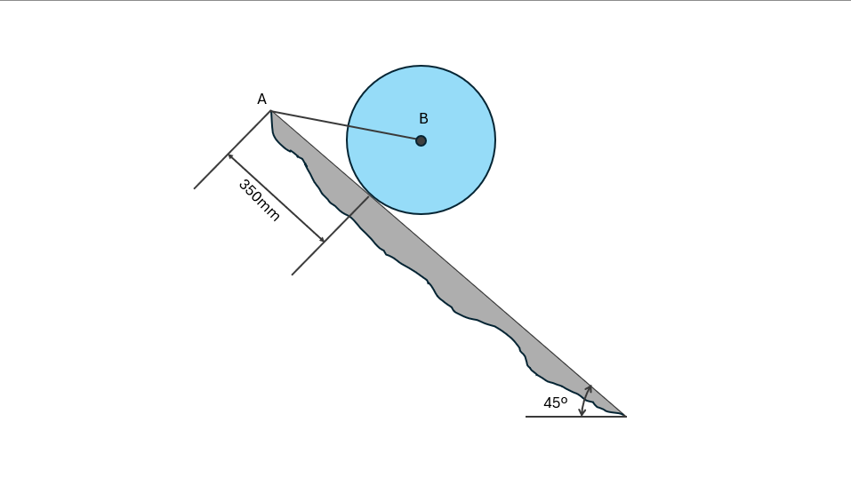
A 40-kg cylinder is held on position on an inclined plane by means of a wire AB as shown in the figure.
Determine the reaction at the surface of the inclined plane.
436.02N @45º
436.02N @74.75º
463.02N @45º
463.02N @74.75º
Determine the tension in the wire.
319.5N
392.4N
350N
326.75N
### Cylinder in equilibrium on the incline
The cylinder weight is
$$W=mg=40(9.81)=392.4 \text{N}.$$
There are three concurrent forces on the cylinder: its weight $W$, the plane reaction $R$ normal to the $45^\circ$ incline, and the wire tension $T$ along $AB$. From the geometry of wire $AB$, its direction is $15.25^\circ$ above the horizontal toward $A$.
Resolve forces into horizontal and vertical components:
$$\sum F_x=0:\qquad Rcos45^\circ-Tcos15.25^\circ=0,$$
$$\sum F_y=0:\qquad Rsin45^\circ+Tsin15.25^\circ-392.4=0.$$
Solving gives
$$T=\boxed{319.5 \text{N}},$$
$$R=\boxed{436.02 \text{N at }45^\circ}. $$
The reaction direction is perpendicular to the inclined surface.
Question Bank: q285
PSAD - Statics / Moment of Forces / Engr. Janclyde Espinosa (Clidez)
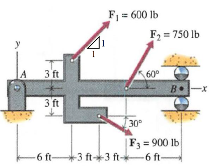
Three forces are applied to a beam. Determine the moments produced by each of the forces about point A and find their resultant moment.
Moment about A caused by F1.
1272.79lb-ft (counter-clockwise)
1272.79lb-ft (clockwise)
6388.27lb-ft (counter-clockwise)
6388.27lb-ft (clockwise)
Moment about A caused by F2.
7794.23lb-ft (counter-clockwise)
7794.23lb-ft (clockwise)
3897.11lb-ft (counter-clockwise)
3897.11lb-ft (clockwise)
Moment about A caused by F3.
1711.73lb-ft (clockwise)
1711.73lb-ft (counter-clockwise)
2545.56lb-ft (counter-clockwise)
2545.56lb-ft (clockwise)
Total moment about A.
7355.29lb-ft (counter-clockwise)
7355.29lb-ft (clockwise)
8233.17lb-ft (counter-clockwise)
8233.17lb-ft (clockwise)
### Moments of the three forces about $A$
Use the scalar moment equation
$$M_A=xF_y-yF_x,$$
where counter-clockwise moments are positive.
For $F_1=600 \text{lb}$ at $45^\circ$, applied at $(x,y)=(6,3) \text{ft}$,
$$F_{1x}=F_{1y}=600\left(\frac1{\sqrt2}\right)=424.26 \text{lb},$$
$$M_{A1}=6(424.26)-3(424.26)=\boxed{1272.79 \text{lb-ft (counter-clockwise)}}.$$
For $F_2=750 \text{lb}$ at $60^\circ$, applied $12 \text{ft}$ from $A$ on the $x$ axis,
$$M_{A2}=12[750\sin60^\circ]=\boxed{7794.23 \text{lb-ft (counter-clockwise)}}.$$
For $F_3=900 \text{lb}$ at $30^\circ$ below the horizontal, applied at $(9,-3) \text{ft}$,
$$F_{3x}=900\cos30^\circ,\qquad F_{3y}=-900\sin30^\circ,$$
$$M_{A3}=9F_{3y}-(-3)F_{3x}=\boxed{1711.73 \text{lb-ft (clockwise)}}.$$
Therefore
$$M_A=1272.79+7794.23-1711.73=\boxed{7355.29 \text{lb-ft (counter-clockwise)}}.$$
Compute the horizontal and vertical components of the support reactions of the beam shown.
What is the internal horizontal reaction at C?
0
10
20
15
What is the internal vertical reaction at C?
10
20
15
40
What is the horizontal reaction at A?
0
10
74
20
What is the vertical reaction at A?
18
16
14
12
What is the vertical reaction at B?
56
42
64
68
### Compound-beam reactions
Separate the beam at the internal connection $C$. The right segment gives the internal vertical force; the loading is vertical, so the internal horizontal force is zero:
$$C_x=\boxed{0},\qquad C_y=\boxed{10 \text{kN}}.$$
Apply equilibrium to the left segment and then to the complete beam:
$$A_x=\boxed{0},\qquad A_y=\boxed{18 \text{kN}},\qquad B_y=\boxed{56 \text{kN}}.$$
Compute the horizontal and vertical components of the support reactions of the compound beam shown. Each support is labeled as A, B, C, and D, respectively.
What is the horizontal reaction at A?
0
10
20
15
What is the vertical reaction at A?
20
10
15
40
What is the vertical reaction of the internal roller at B?
20
10
15
30
What is the vertical reaction at C?
30.67
26.67
27.85
28.75
What is the horizontal reaction at D?
0
10
15
40
What is the vertical reaction at D?
1.33
2.67
5.33
4.67
### Reactions of the compound beam
Analyze the left span first. Its $10 \text{kN/m}$ load over $4 \text{m}$ gives equal end reactions of $20 \text{kN}$:
$$A_x=\boxed0,\qquad A_y=\boxed{20 \text{kN}},\qquad B_y=\boxed{20 \text{kN}}.$$
Use the transferred hinge force as a load on the right segment and take moments about $C$. The remaining reactions are
$$C_y=\boxed{30.67 \text{kN}},\qquad D_x=\boxed0,\qquad D_y=\boxed{1.33 \text{kN}}.$$
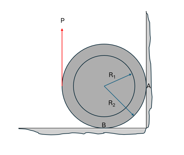
If the coefficient of static friction at contact points A and B in the figure below is μs=0.25, the weight of the spool is 70kg, and R1=0.6m; R2=0.9m, determine the following:
Maximum force P that can be applied without causing the spool to move.
210.214
448.457
112.114
103.48
Normal Reaction at B.
448.457
210.214
112.114
103.48
Normal Reaction at A.
112.114
448.457
210.214
103.48
### Spool at impending motion
At impending slip, $F_A=mu_sN_A$ and $F_B=mu_sN_B$, with $mu_s=0.25$. Use force equilibrium in the horizontal and vertical directions and take moments about the spool center. The applied pull acts at radius $R_1$, while the contact friction acts at radius $R_2$.
Solving the three equilibrium equations gives
$$P_{\max}=\boxed{210.214 \text{N}},$$
$$N_B=\boxed{448.457 \text{N}},\qquad N_A=\boxed{112.114 \text{N}}.$$
Question Bank: q527
PSAD - Statics / Resultant/Equilibrium of Nonconcurrent Force Systems / Engr. Janclyde Espinosa (Clidez)
For the system shown:
Calculate the location of the resultant from point D.
0.832m left of D
0.832m right of D
1.5m left of D
1.5m right of D
Determine the horizontal distance from the resultant to point D and indicate the direction.
1.5m left of D
1.5m right of D
0.832m left of D
0.832m right of D
Determine the vertical distance from the resultant to point D and indicate the direction.
1m above D
1m below D
1.5m above D
1.5m below D
Determine the distance from point B to the resultant force.
0.55m
0.66m
0.44m
0.33m
Resolve the forces in the figure into components. Their resultant is: $$R_x=5-20=-15\text{ N},\qquad R_y=-10\text{ N}$$ The resultant line is located by equating the moment of the force system to the moment of the resultant about $D$. Using the shown 1-m grid gives the line of action through the point: $$x_R=-1.5\text{ m},\qquad y_R=+1.0\text{ m}$$ Thus the resultant is $1.5\text{ m}$ left of $D$ and $1.0\text{ m}$ above $D$. Its specified location measured from $D$ is $0.832\text{ m}$ to the left.
For the distance from $B$, write the resultant line in the grid coordinates and use the point-to-line distance formula. This gives: $$d_B=0.55\text{ m}$$
Therefore, the requested answers are 0.832 m left of D, 1.5 m left of D, 1 m above D, and 0.55 m from $B$.
Question Bank: q528
PSAD - Statics / Resultant/Equilibrium of Nonconcurrent Force Systems / Engr. Deguma
The uniform 30kg bar with end rollers is supported by the horizontal and vertical surfaces and the wire AC.
Determine the tension in the wire in Newtons.
295.34
235.44
196.20
73.55
Determine the reaction at A in Newtons.
73.55
76.48
83.42
90.54
Determine the moment at B in Newton-meter.
235.44
295.34
196.20
194.72
The bar has a 3-4-5 geometry: $AB=2\text{ m}$, with horizontal and vertical projections $1.6\text{ m}$ and $1.2\text{ m}$. The cable direction from $A$ to $C$ has components proportional to $(1.6,1.8)$, so: $$\sin\alpha=\frac{1.8}{\sqrt{1.6^2+1.8^2}}=0.7474$$ The bar weight is $W=30(9.81)=294.3\text{ N}$. Taking moments about $B$ gives the cable tension: $$T=295.34\text{ N}$$ Vertical equilibrium then gives the floor reaction at $A$: $$R_A+T\sin\alpha-W=0$$ $$R_A=294.3-295.34(0.7474)=73.55\text{ N}$$ The moment of the bar weight about $B$ is: $$M_B=W(0.8)=294.3(0.8)=235.44\text{ N}\cdot\text{m}$$
Therefore, the cable tension is 295.34 N, the reaction at $A$ is 73.55 N, and the moment at $B$ is 235.44 N·m.
Three-Legged Stool: CC2 Item
PSAD - Statics / Resultant/Equilibrium of Nonconcurrent Force Systems / Engr. Deguma
A three-legged stool is subjected to the load P as shown. If P=200N, compute the following:
Reaction under leg A in Newtons
106.67
46.67
143.33
56.67
Reaction under leg B in Newtons
46.67
106.67
143.33
56.67
Reaction under leg C in Newtons
46.67
106.67
143.33
56.67
The three leg reactions are vertical and must satisfy: $$R_A+R_B+R_C=200\text{ N}$$ Use the plan dimensions of the 120°-spaced legs and take moments about each pair of legs. The eccentric location of the 200-N load gives: $$R_A=106.67\text{ N}$$ By the symmetry of the load location with respect to legs $B$ and $C$: $$R_B=R_C$$ $$R_B=R_C=\frac{200-106.67}{2}=46.67\text{ N}$$
Therefore, the reactions under legs $A$, $B$, and $C$ are 106.67 N, 46.67 N, and 46.67 N, respectively.
Question Bank: q531
PSAD - Statics / Resultant/Equilibrium of Nonconcurrent Force Systems / Engr. Deguma
The weight of the cylinder in the figure shown is 1000N.
Compute the normal force between the cylinder and bar AB.
1666.67
833.33
1000.00
1118.03
Compute the tension in cable BC.
833.33
1118.03
1000.00
1666.67
Compute the reaction at the hinged support at A.
1118.03
1666.67
1000.00
833.33
The bar has a 6-8-10 geometry, so its direction has components $(0.6,0.8)$. The normal force between the cylinder and the bar is perpendicular to the bar; its vertical component is $0.6N$. Equilibrium of the cylinder gives: $$0.6N=1000\quad\Rightarrow\quad N=1666.67\text{ N}$$ The force exerted by the cylinder on the bar has components $(1333.33,-1000)\text{ N}$ and acts $4\text{ m}$ from $A$. Taking moments about $A$ for the bar: $$T_{BC}(8)=1666.67(4)$$ $$T_{BC}=833.33\text{ N}$$ The hinge components are found from force equilibrium: $$A_x=500\text{ N (left)},\qquad A_y=1000\text{ N (up)}$$ $$R_A=\sqrt{500^2+1000^2}=1118.03\text{ N}$$
Therefore, the normal force is 1666.67 N, the cable tension is 833.33 N, and the hinge reaction is 1118.03 N.
Question Bank: q532
PSAD - Statics / Resultant/Equilibrium of Nonconcurrent Force Systems / Engr. Deguma
For the figure shown, calculate the angle of tilt, θ, so that the contact force at B will be one-half that of A for the smooth cylinder.
Answer:
18.43º
20.54º
17.56º
23.20º
Because the contacts are smooth, the reactions are normal to the two $45^\circ$ faces. Let $R_B=R_A/2$. Resolving horizontal equilibrium along the tilted geometry gives: $$R_A\cos(\theta+135^\circ)+\frac{R_A}{2}\cos(\theta+45^\circ)=0$$ After expanding and simplifying: $$-\left(\cos\theta+\sin\theta\right)+\frac12\left(\cos\theta-\sin\theta\right)=0$$ $$\tan\theta=-\frac13$$ The negative sign only indicates the sense of tilt shown. Its magnitude is: $$\theta=\tan^{-1}\left(\frac13\right)=18.43^\circ$$
In the figure shown, if w=800N/m, compute the following:
The reaction at A in kN.
3.33
2.40
4.20
3.67
The horizontal reaction at B in kN.
2.40
3.33
4.20
3.67
The vertical reaction at B in Newtons.
133
233
166
240
Question Bank: q550
PSAD - Structural Theory / Equilibrium of Rigid Bodies / Engr. Deguma
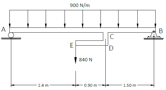
The rigid bar CDE is welded at point C to the uniform steel beam shown in. A steel beam has dimensions b=25 mm and d = 85 mm. Use
E = 200 GPa.
Determine the reaction at the roller support in Newtons.
2580
2340
2150
1870
Determine the rotation (in degrees) at the roller support.
1.22
1.02
0.67
2.43
Determine the deflection (in mm) at the midspan.
33.12
16.80
22.10
27.60
The beam span is $L=2.4+0.9+1.5=4.8\text{ m}$. The uniform load is $w=900\text{ N/m}$, so its resultant is $wL=4320\text{ N}$ at $2.4\text{ m}$ from $A$. The 840-N force applied through the rigid bar acts at $2.4\text{ m}$ from $A$. Taking moments about $A$: $$R_B(4.8)=4320(2.4)+840(2.4)$$ $$R_B=2580\text{ N}$$ The section moment of inertia is: $$I=\frac{bd^3}{12}=\frac{25(85)^3}{12}=1.279\times10^6\text{ mm}^4$$ Using $EI\,v''=M(x)$, integrating the piecewise bending-moment equation, and imposing $v_A=v_B=0$ gives: $$\theta_B=0.0213\text{ rad}=1.22^\circ$$ $$v_{mid}=33.12\text{ mm}$$
Therefore, the roller reaction is 2580 N, its rotation is 1.22°, and the midspan deflection is 33.12 mm.
Question Bank: q554
PSAD - Statics / Resultant/Equilibrium of Nonconcurrent Force Systems / Engr. Deguma
For the truss shown,
Which of the following most nearly gives the horizontal component of the
resultant of forces acting in the truss?
4000N
3000N
5000N
6000N
Which of the following most nearly gives the vertical component of the
resultant of forces acting in the truss.
10000N
11000N
9000N
12000N
Which of the following most nearly gives the horizontal distance from the
left support where the resultant of the forces acts.
4.80m
3.60m
5.40m
6.80m
Resolve every inclined force in the truss into horizontal and vertical components, using the member geometry, and add the vertical point loads. The force summations are: $$\sum F_x=4000\text{ N},\qquad \sum F_y=10000\text{ N}$$ Take moments of all applied forces about the left support and equate this to the moment of the resultant. This locates its line of action at: $$x_R=4.80\text{ m from the left support}$$
Therefore, the resultant has components 4000 N horizontal and 10000 N vertical, and acts 4.80 m from the left support.
Sign Board with Given Weight
PSAD - Statics / Resultant/Equilibrium of Nonconcurrent Force Systems / Mastermatician
Consider the figure shown below. Neglect the self-weight of members AB and BC.
Determine the horizontal reaction at A.
4.59
2.34
2.16
5.40
Determine the vertical reaction at C.
2.34
4.59
2.16
5.40
Member $AB$ is a two-force member. Its geometry is a $3$-$2$-$\sqrt{13}$ triangle. The $5.4$-kN weight acts $1.7$ m from $C$ on the 3-m member $CB$. Taking moments about $C$: $$B_y(3)=5.4(1.7)\quad\Rightarrow\quad B_y=3.06\text{ kN}$$ Since the force at $B$ is along $AB$, its horizontal component is: $$B_x=B_y\left(\frac32\right)=4.59\text{ kN}$$ Vertical equilibrium of member $CB$ gives: $$C_y=5.4-3.06=2.34\text{ kN}$$
Therefore, the horizontal reaction at $A$ is 4.59 kN and the vertical reaction at $C$ is 2.34 kN.
Question Bank: q770
PSAD - Statics / Resultant/Equilibrium of Nonconcurrent Force Systems / Engr. Clidez
The cable-and-pulley system shown is used to lift a 600-lb stone.
Determine the force $P$ that must be applied to the cable at $A$
300
600
579.6
670.8
Determine the resultant force exerted by pulley $C$ on pin $B$
579.6
670.8
600
300
Since the cable and pulleys are ideal, the tension is constant throughout the cable. Thus,
$$T=P$$
The movable pulley at $D$ is supported by two vertical cable segments. Each segment exerts an upward force equal to the cable tension $T$.
Applying vertical-force equilibrium to the stone and movable pulley,
$$\sum F_y=0$$
$$2T-600=0$$
$$T=300\text{ lb}$$
Since $P=T$, the required force at $A$ is
$$\boxed{P=300\text{ lb}}$$
To determine the force exerted by pulley $C$ on pin $B$, consider the two cable tensions acting on pulley $C$. Each tension has a magnitude of $300\text{ lb}$. One acts vertically downward, while the other acts downward along the inclined cable at $30^\circ$ from the vertical.