CE Board Exam Randomizer

⬅ Back to Subject Topics

Resultant of Parallel Force Systems

Concept Diagram 1 Concept Diagram 2 Concept Diagram 3 Concept Diagram 4 Concept Diagram 5 Concept Diagram 6 Concept Diagram 7 Concept Diagram 8 Concept Diagram 9

Problem: Parallel Forces along the x-axis

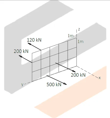
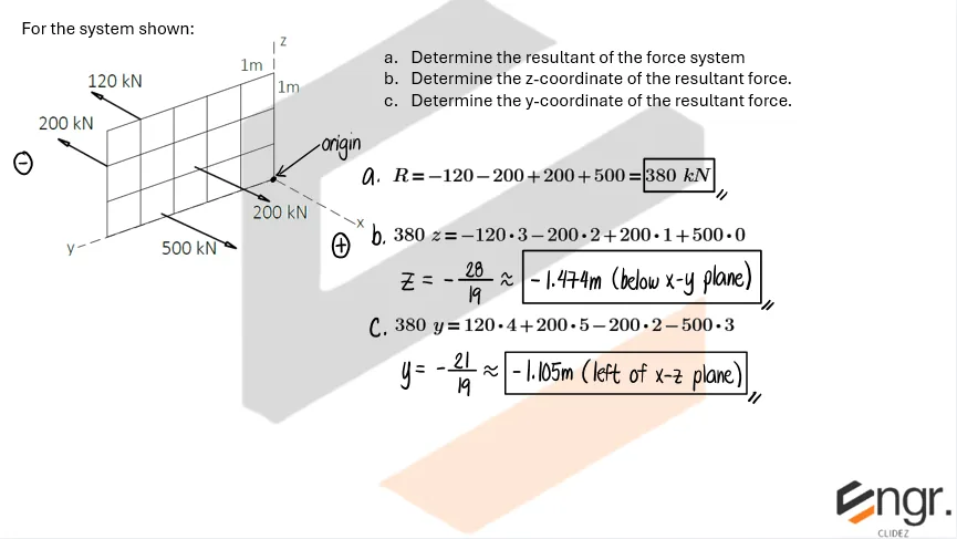
For the system shown:
a. Determine the resultant of the force system.
b. Determine the z-coordinate of the resultant force.
c. Determine the y-coordinate of the resultant force.

Resultant of Parallel Force Systems | Statics of Rigid Bodies – Problem 1: Parallel Forces along the x-axis – Diagram Resultant of Parallel Force Systems | Statics of Rigid Bodies – Problem 1: Parallel Forces along the x-axis – Diagram Resultant of Parallel Force Systems | Statics of Rigid Bodies – Problem 1: Parallel Forces along the x-axis – Diagram

See images:

Resultant of Parallel Force Systems | Statics of Rigid Bodies – Problem 1: Parallel Forces along the x-axis – Diagram Resultant of Parallel Force Systems | Statics of Rigid Bodies – Problem 1: Parallel Forces along the x-axis – Diagram Resultant of Parallel Force Systems | Statics of Rigid Bodies – Problem 1: Parallel Forces along the x-axis – Diagram Resultant of Parallel Force Systems | Statics of Rigid Bodies – Problem 1: Parallel Forces along the x-axis – Diagram

Problem:

Resultant of Parallel Force Systems | Statics of Rigid Bodies – Problem 2: – Diagram Resultant of Parallel Force Systems | Statics of Rigid Bodies – Problem 2: – Diagram Resultant of Parallel Force Systems | Statics of Rigid Bodies – Problem 2: – Diagram

See images:

Resultant of Parallel Force Systems | Statics of Rigid Bodies – Problem 2: – Diagram Resultant of Parallel Force Systems | Statics of Rigid Bodies – Problem 2: – Diagram Resultant of Parallel Force Systems | Statics of Rigid Bodies – Problem 2: – Diagram Resultant of Parallel Force Systems | Statics of Rigid Bodies – Problem 2: – Diagram

Problem:

Resultant of Parallel Force Systems | Statics of Rigid Bodies – Problem 3: – Diagram Resultant of Parallel Force Systems | Statics of Rigid Bodies – Problem 3: – Diagram Resultant of Parallel Force Systems | Statics of Rigid Bodies – Problem 3: – Diagram

See images:

Resultant of Parallel Force Systems | Statics of Rigid Bodies – Problem 3: – Diagram Resultant of Parallel Force Systems | Statics of Rigid Bodies – Problem 3: – Diagram Resultant of Parallel Force Systems | Statics of Rigid Bodies – Problem 3: – Diagram Resultant of Parallel Force Systems | Statics of Rigid Bodies – Problem 3: – Diagram

Problem:

Resultant of Parallel Force Systems | Statics of Rigid Bodies – Problem 4: – Diagram Resultant of Parallel Force Systems | Statics of Rigid Bodies – Problem 4: – Diagram Resultant of Parallel Force Systems | Statics of Rigid Bodies – Problem 4: – Diagram

See images:

Resultant of Parallel Force Systems | Statics of Rigid Bodies – Problem 4: – Diagram Resultant of Parallel Force Systems | Statics of Rigid Bodies – Problem 4: – Diagram Resultant of Parallel Force Systems | Statics of Rigid Bodies – Problem 4: – Diagram Resultant of Parallel Force Systems | Statics of Rigid Bodies – Problem 4: – Diagram

Problem:

Resultant of Parallel Force Systems | Statics of Rigid Bodies – Problem 5: – Diagram Resultant of Parallel Force Systems | Statics of Rigid Bodies – Problem 5: – Diagram Resultant of Parallel Force Systems | Statics of Rigid Bodies – Problem 5: – Diagram

See images:

Resultant of Parallel Force Systems | Statics of Rigid Bodies – Problem 5: – Diagram Resultant of Parallel Force Systems | Statics of Rigid Bodies – Problem 5: – Diagram Resultant of Parallel Force Systems | Statics of Rigid Bodies – Problem 5: – Diagram Resultant of Parallel Force Systems | Statics of Rigid Bodies – Problem 5: – Diagram

Problem:

Resultant of Parallel Force Systems | Statics of Rigid Bodies – Problem 6: – Diagram Resultant of Parallel Force Systems | Statics of Rigid Bodies – Problem 6: – Diagram Resultant of Parallel Force Systems | Statics of Rigid Bodies – Problem 6: – Diagram

See images:

Resultant of Parallel Force Systems | Statics of Rigid Bodies – Problem 6: – Diagram Resultant of Parallel Force Systems | Statics of Rigid Bodies – Problem 6: – Diagram Resultant of Parallel Force Systems | Statics of Rigid Bodies – Problem 6: – Diagram Resultant of Parallel Force Systems | Statics of Rigid Bodies – Problem 6: – Diagram

Problem:

Resultant of Parallel Force Systems | Statics of Rigid Bodies – Problem 7: – Diagram Resultant of Parallel Force Systems | Statics of Rigid Bodies – Problem 7: – Diagram Resultant of Parallel Force Systems | Statics of Rigid Bodies – Problem 7: – Diagram

See images:

Resultant of Parallel Force Systems | Statics of Rigid Bodies – Problem 7: – Diagram Resultant of Parallel Force Systems | Statics of Rigid Bodies – Problem 7: – Diagram Resultant of Parallel Force Systems | Statics of Rigid Bodies – Problem 7: – Diagram Resultant of Parallel Force Systems | Statics of Rigid Bodies – Problem 7: – Diagram

Problem:

Resultant of Parallel Force Systems | Statics of Rigid Bodies – Problem 8: – Diagram Resultant of Parallel Force Systems | Statics of Rigid Bodies – Problem 8: – Diagram Resultant of Parallel Force Systems | Statics of Rigid Bodies – Problem 8: – Diagram

See images:

Resultant of Parallel Force Systems | Statics of Rigid Bodies – Problem 8: – Diagram Resultant of Parallel Force Systems | Statics of Rigid Bodies – Problem 8: – Diagram Resultant of Parallel Force Systems | Statics of Rigid Bodies – Problem 8: – Diagram Resultant of Parallel Force Systems | Statics of Rigid Bodies – Problem 8: – Diagram
-->

Problem (Resultant of two parallel loads):

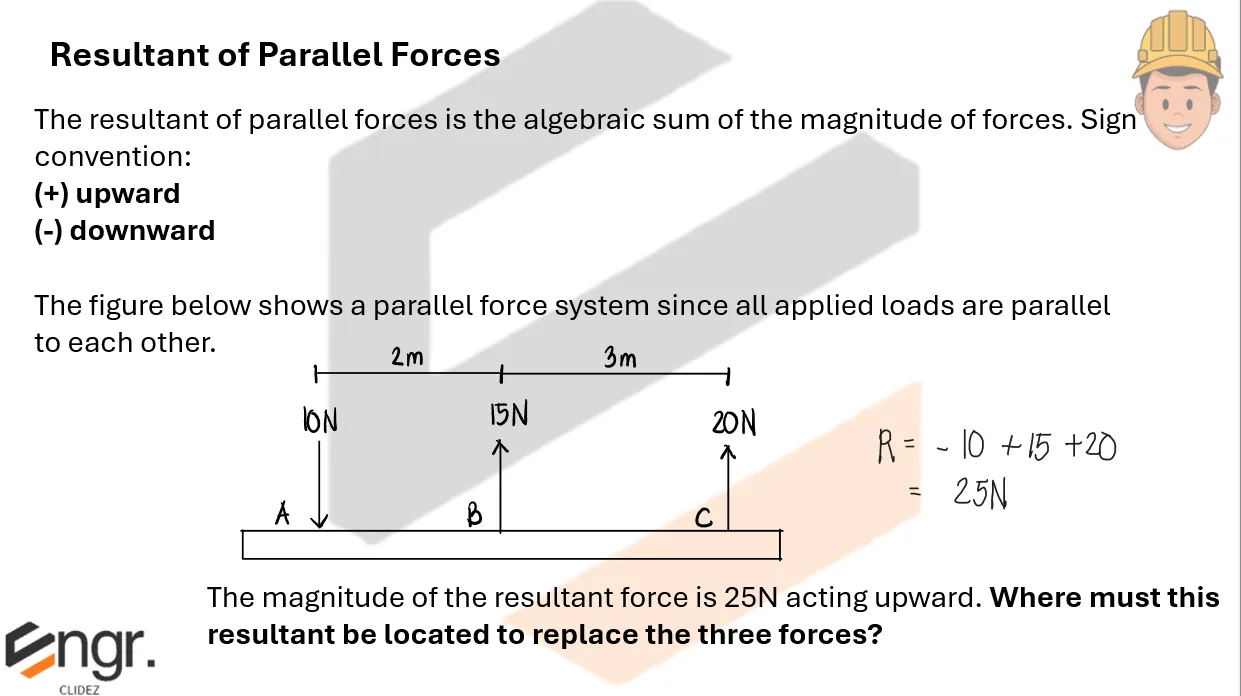
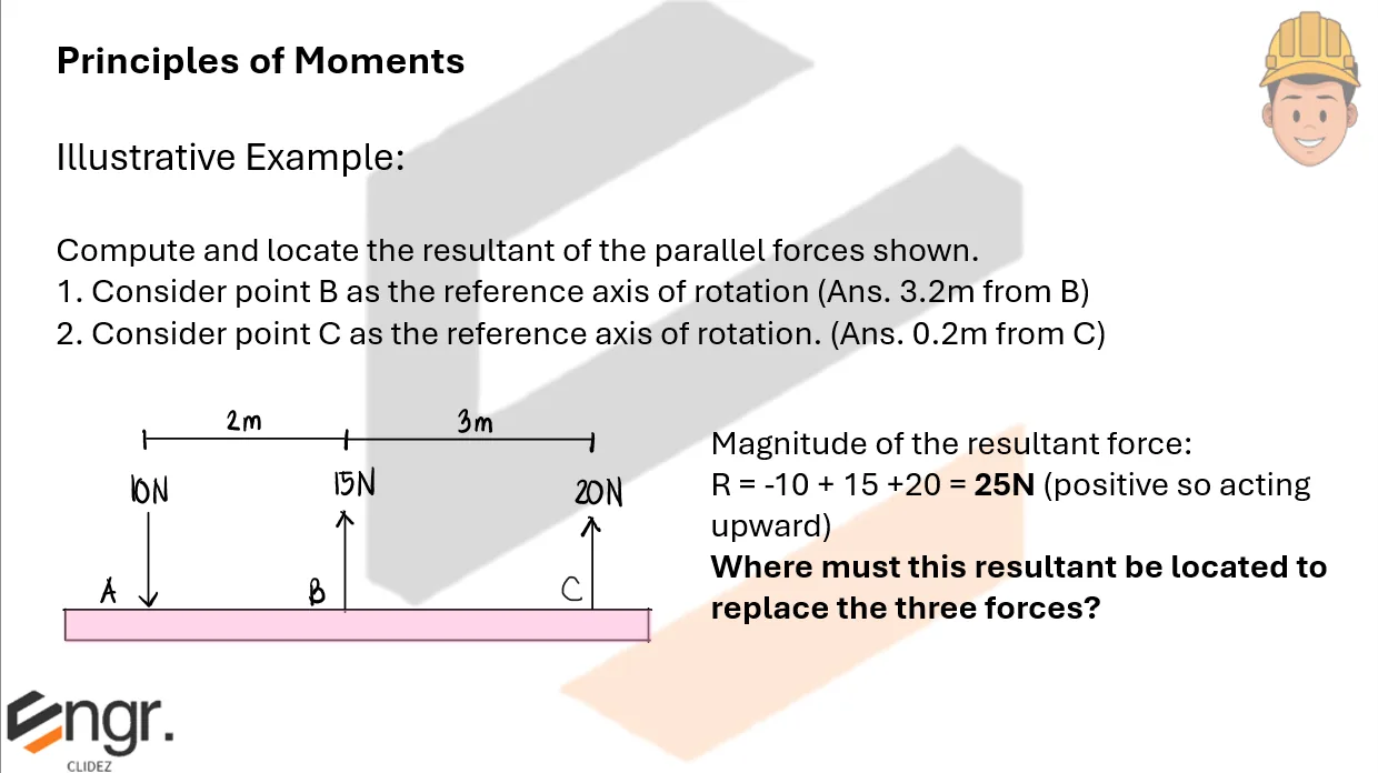
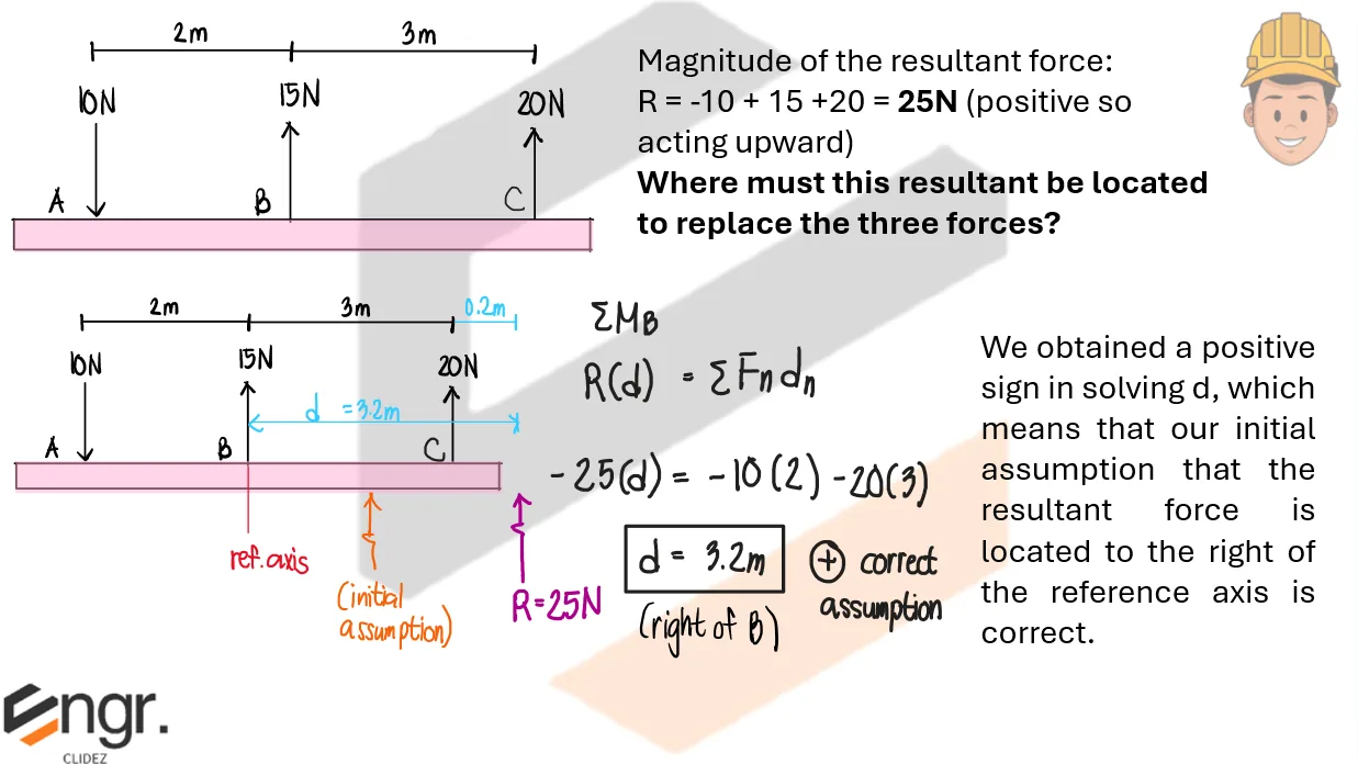
Two downward loads act on a beam: 30kN at 2m from A and 20kN at 6m from A. Determine the resultant and its location from A.

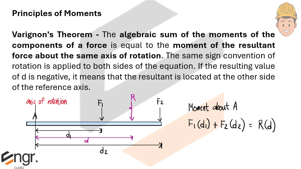
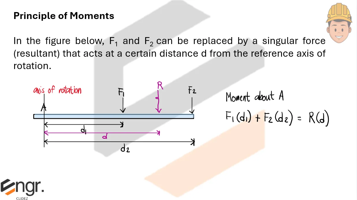
The magnitude is the algebraic sum of the parallel forces. Locate it by equating moments about A.

\[ \begin{aligned} R &= 30+20=50\ \text{kN downward} \\ Rx &= 30(2)+20(6) \\ 50x &= 180 \\ x &= 3.60\ \text{m} \end{aligned} \] $\boxed{R=50\ \text{kN downward}},\qquad \boxed{x=3.60\ \text{m from A}}$

Problem (Opposite parallel forces):

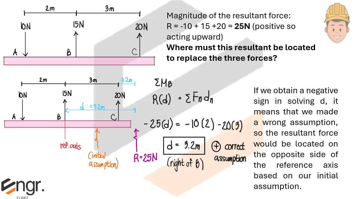
An 80kN upward force acts at A. Downward forces of 30kN and 20kN act 3m and 7m to the right of A, respectively. Determine the resultant and its line of action from A.

Take upward as positive. A negative location means the resultant lies to the left of A.

\[ \begin{aligned} R &= 80-30-20=30\ \text{kN upward} \\ Rx &= -30(3)-20(7)=-230\ \text{kN-m} \\ 30x &= -230 \\ x &= -7.67\ \text{m} \end{aligned} \] $\boxed{R=30\ \text{kN upward}},\qquad \boxed{x=7.67\ \text{m left of A}}$

Problem (Parallel loads with a triangular load):

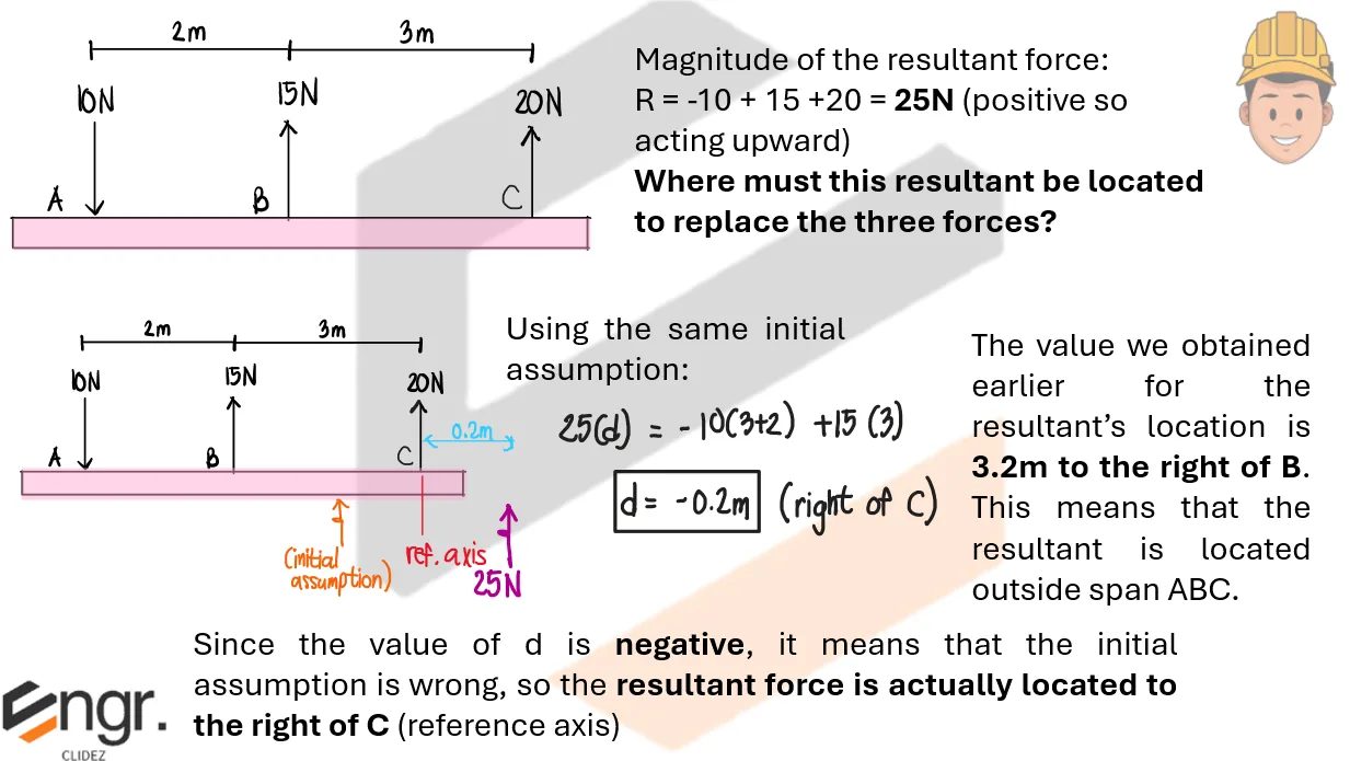
A triangular distributed load varies from zero at A to 12kN/m at B over a 6m span. A 15kN point load also acts 8m from A. Determine the single downward resultant and its location from A.

Replace the triangular load by its area acting at two-thirds of the base from the zero-intensity end.

\[ \begin{aligned} W_t &= {1\over2}(6)(12)=36\ \text{kN} \\ x_t &= {2\over3}(6)=4\ \text{m} \\ R &= 36+15=51\ \text{kN} \\ Rx &= 36(4)+15(8)=264 \\ x &= 5.18\ \text{m} \end{aligned} \] $\boxed{R=51\ \text{kN downward}},\qquad \boxed{x=5.18\ \text{m from A}}$
Scroll to zoom

Exam Generator Problems

Additional board-style practice items for this topic.

Question Bank: q586

PSAD - Statics / Resultant of Parallel Force Systems / Mastermatician

Beam AB supports an overhead hoist carrying a load, W = 500kN, and three forces F1 = 300kN, F2 = 300kN, and F3 = 200kN.
.
L1=3m
L2=5m
L3=2m
L4=2m

q586

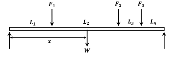
At what distance, x, should the hoist be so that the resultant of the forces with the load will be at the midspan?

  1. 5.0
  2. 10.6
  3. 1.0
  4. 7.6

If the load W is at midspan, what is the resulting reaction at A (kN)?

  1. 608
  2. 358
  3. 650
  4. 858

If the load W is at the support at A, which of the following gives the resulting maximum span moment?

  1. 1367
  2. 2867
  3. 2405
  4. 1500

Part 1.

Total load including the hoist is $300+500+300+200=1300$ kN. The span is $3+5+2+2=12$ m, so midspan is at 6 m from A. For the resultant to pass through midspan:
$1300(6)=300(3)+500x+300(8)+200(10)$
$7800=5300+500x$
$\boxed{x=5.0\text{ m}}$

Part 2.

With $W=500$ kN at midspan, take moments about B to get the reaction at A:
$R_A(12)=300(9)+500(6)+300(4)+200(2)$
$R_A=\frac{7300}{12}=608.33\text{ kN}$
$\boxed{R_A=608\text{ kN}}$

Part 3.

With $W=500$ kN at A, first find reactions:
$R_B(12)=300(3)+300(8)+200(10)=5300$
$R_B=441.67\text{ kN},\quad R_A=1300-441.67=858.33\text{ kN}$
The shear changes sign at the 300-kN load located 8 m from A, so the maximum moment is there:
$M_{max}=858.33(8)-500(8)-300(5)$
$\boxed{M_{max}=1367\text{ kN-m}}$

Question Bank: q592

PSAD - Statics / Resultant of Parallel Force Systems / Mastermatician

The table weighing 420N is to be lifted without tilting by four forces as shown.
Given:
x=2.0m
y=2.4m
F1=120N
F2=90N

q592

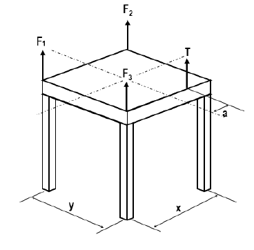
How much is the force T which should be applied at a distance of 0.5 m from centroidal y-axis?

  1. 160
  2. 120
  3. 140
  4. 80

If T = 120 N and a distance a = 0.75 m, what is the maximum weight of the table which can be lifted without tilting?

  1. 390
  2. 130
  3. 260
  4. 520

If T = 120 N and distance a = 0.75 m, what is the value of the force F3 required to lift the table without tilting?

  1. 60
  2. 75
  3. 95
  4. 120

Solution pending in psadquestions/q592.json.