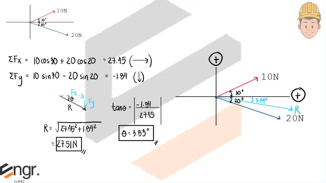
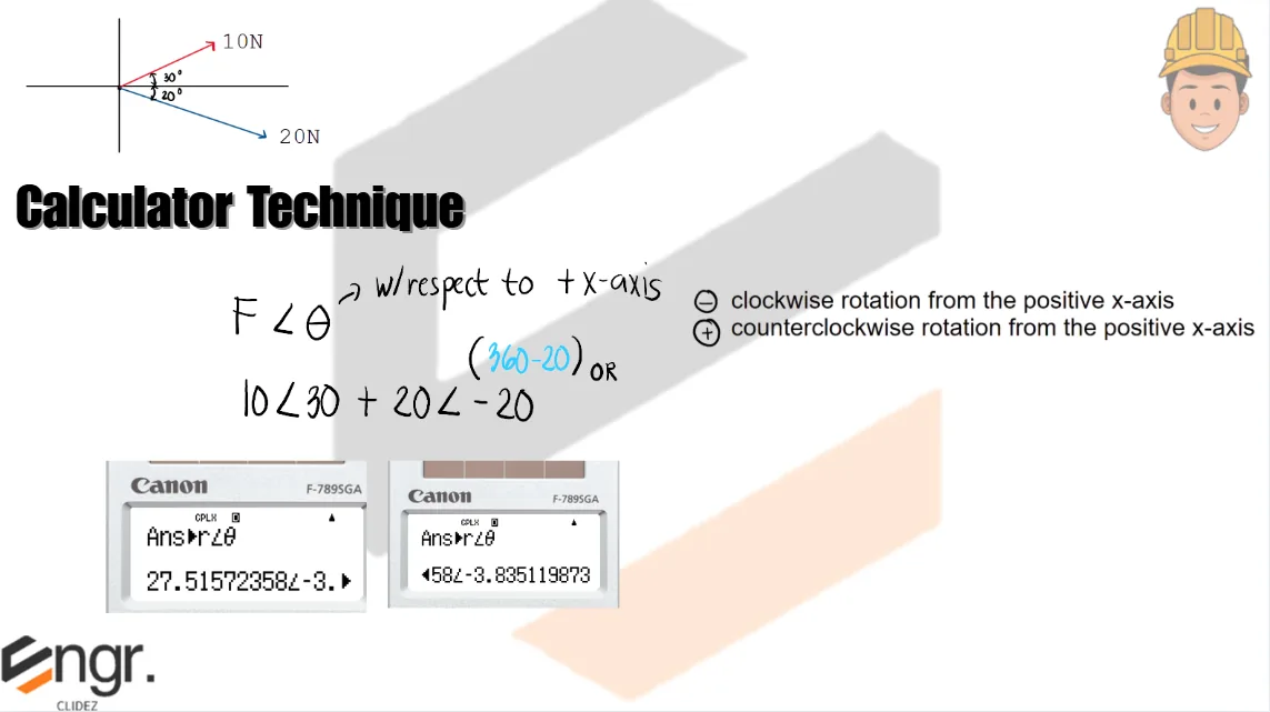
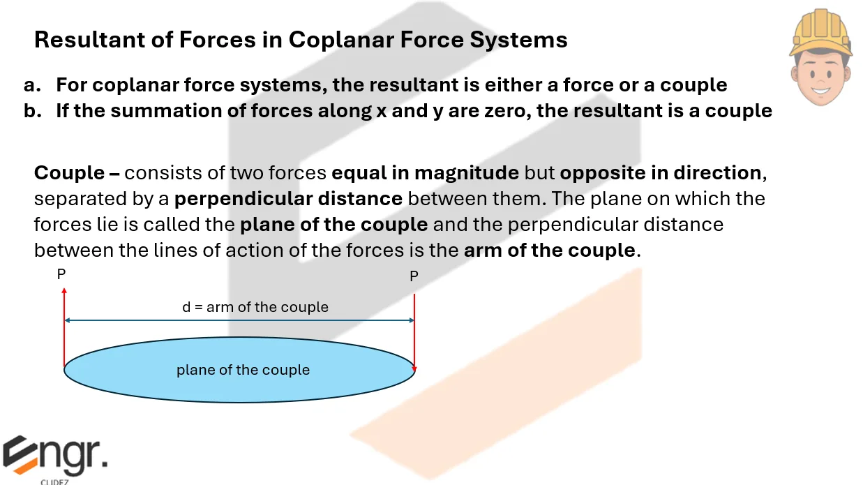
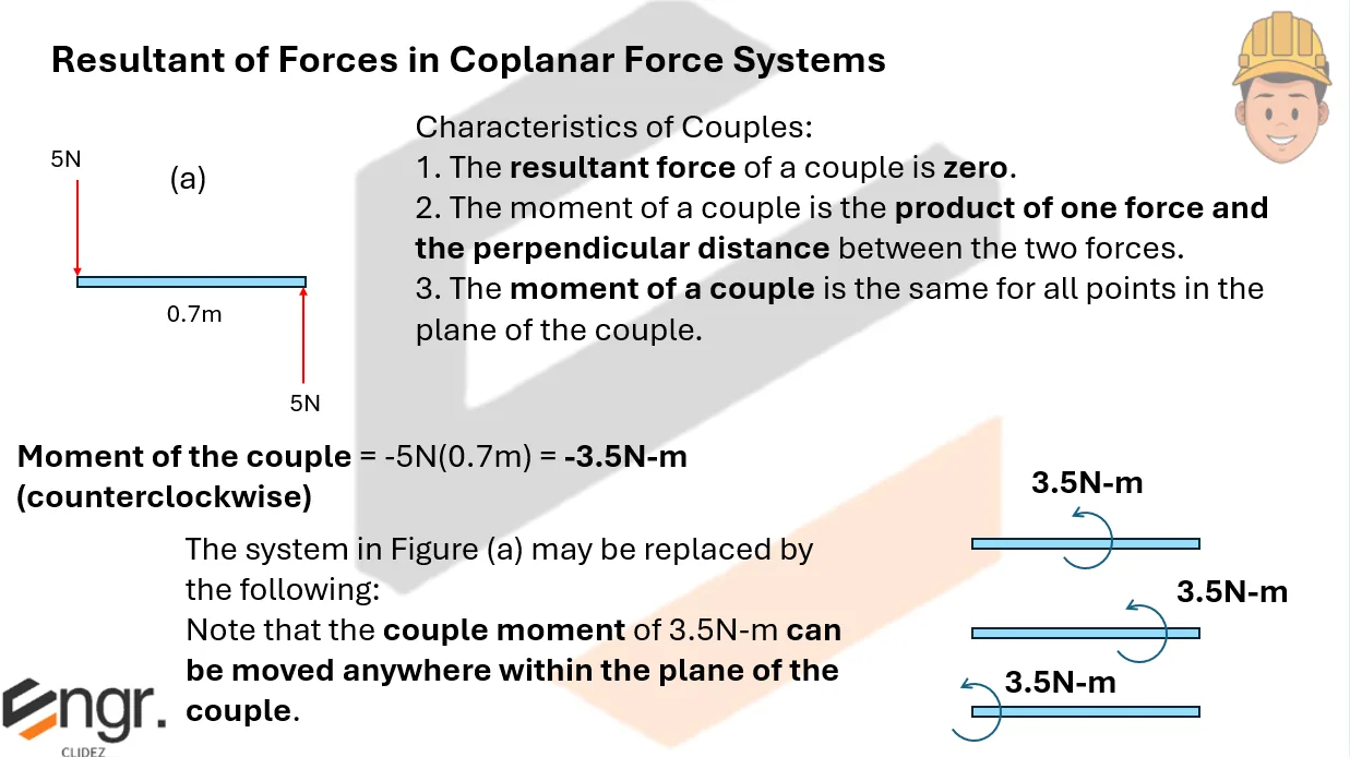
Resultant of Concurrent Force Systems
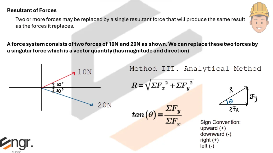
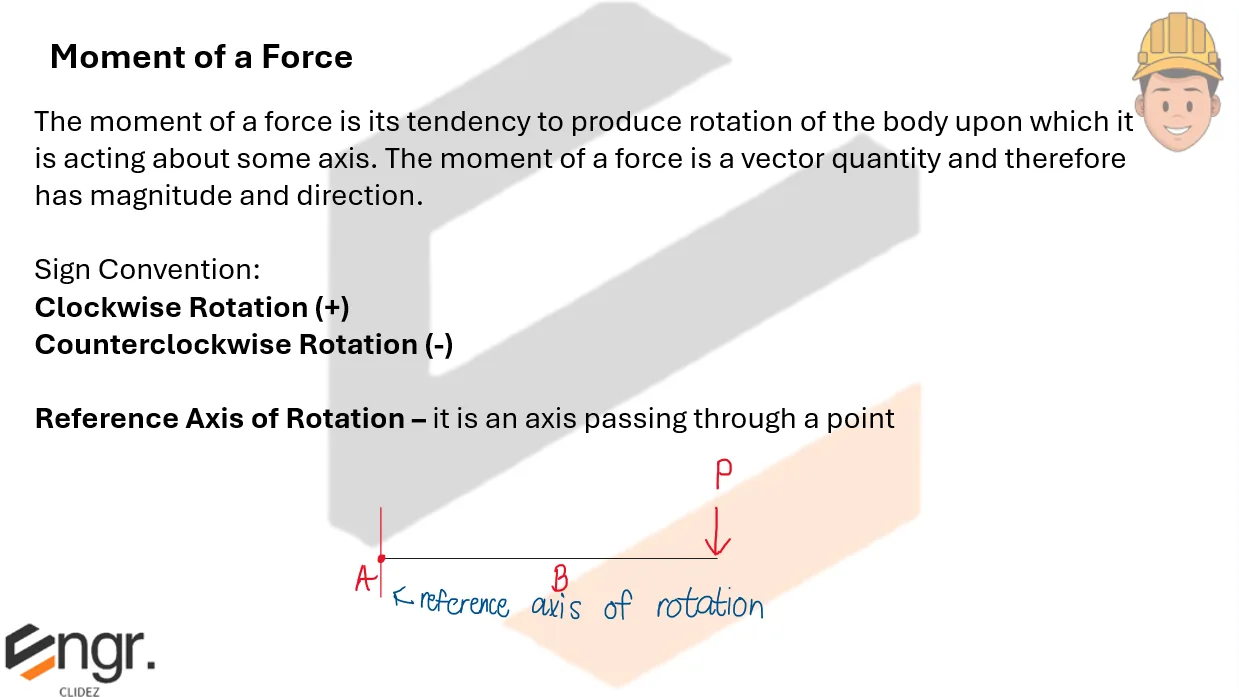
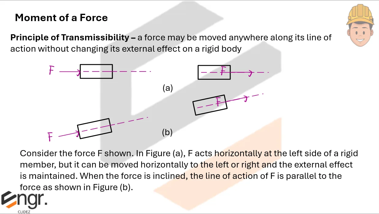
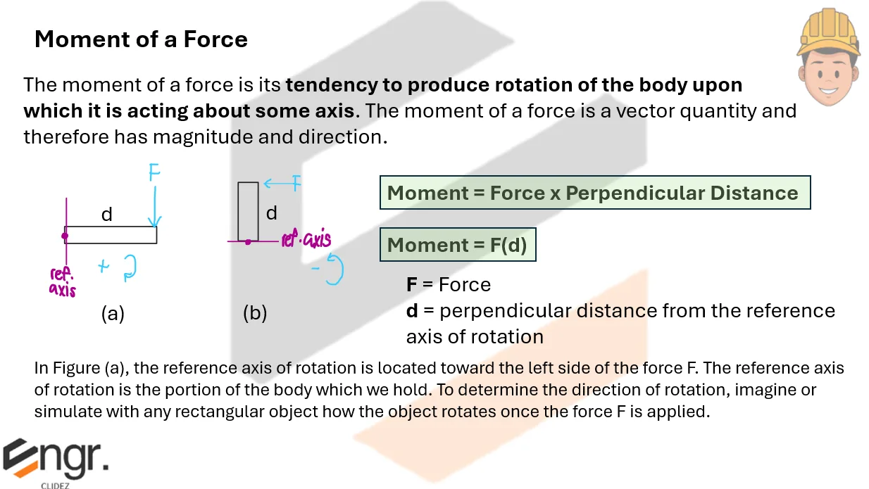
Moment of a Force & Couples
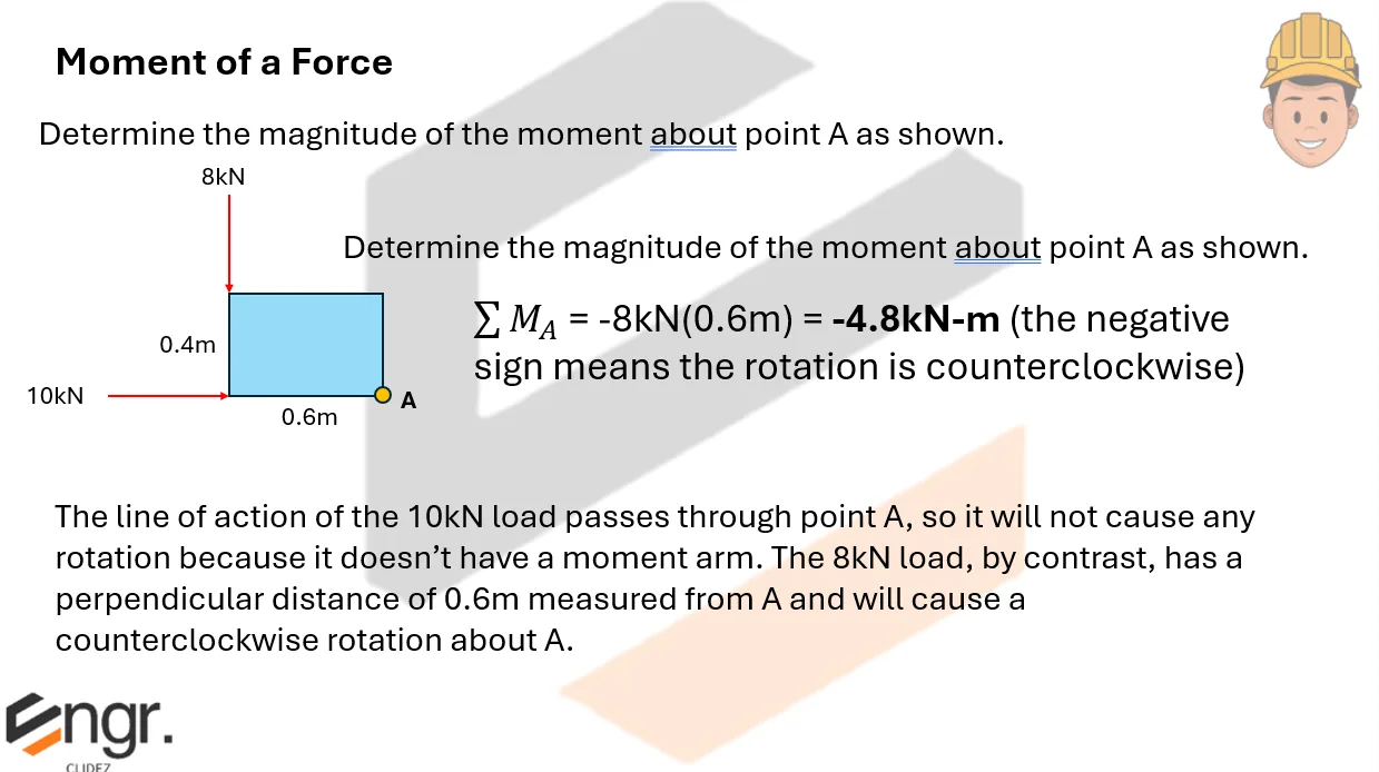

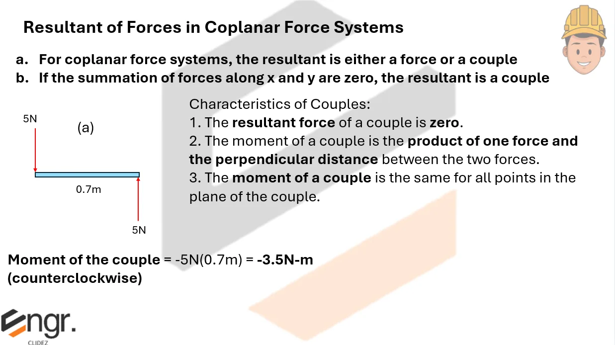


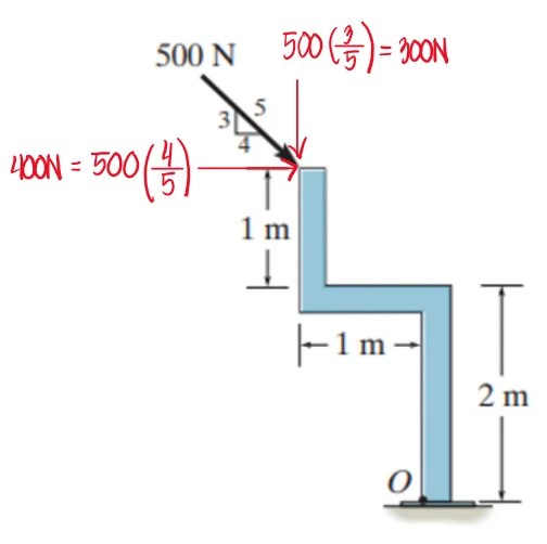
Determine the moment about point O.


$M_o=400N(3m)-300N(1m)=900N-m$ (clockwise)


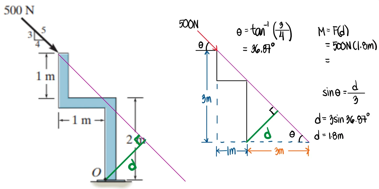
Second solution: Using the perpendicular distance from the line of action of the 500N load to point O:
Determine the moment about point O.

$300(0.3+0.125)+400(0.25)+600cos(60)(0.25)+600sin(60)(0.425)=268.34N \cdot m$

Determine the resultant moment about:
a. Point A
b. Point B
c. Point C
d. Point D

Note: The two 50 N forces, acting upward and downward, form a couple. Consequently, their moment about any point in the figure is equal to the magnitude of one of the forces multiplied by the perpendicular distance (the couple arm) between their lines of action. Observing the direction of the forces as if turning a steering wheel, the couple produces a clockwise rotation. Hence, under the adopted sign convention, the moment contributed by this couple is taken as positive. $$ \text{Solution (Moments): Clockwise is assumed positive } (+) \text{ and counterclockwise is negative } (-). $$ $$ M_A = 50(110) + 60\left(\frac{1}{\sqrt{2}}\right)(110-20) - 60\left(\frac{1}{\sqrt{2}}\right)(115-20-25) - 30(115-20) = 3498.52814 $$ $$ M_B = 50(110) + 60\left(\frac{1}{\sqrt{2}}\right)(25) - 60\left(\frac{1}{\sqrt{2}}\right)(20) = 5712.13203 $$ $$ M_C = 50(110) + 60\left(\frac{1}{\sqrt{2}}\right)(60-20) - 30(25) = 6447.05627 $$ $$ M_D = 50(110) - 30(25) = 4750 $$

Compute the resultant of the three forces shown. Locate its intersection with the x and y-axes. Each square is 1ft on a side.

Sign Convention: Positive along the +x-axis and +y-axis.
$$ \sum F_x=-300\cos60^\circ+360+600.74=810.74\text{ lb} $$ $$ \sum F_y=-300\sin60^\circ+150-400.49=-510.30\text{ lb} $$ $$ R=\sqrt{(810.74)^2+(510.30)^2}=957.97\text{ lb} $$ $$ \theta=\tan^{-1}\left(\frac{510.30}{810.74}\right)=32.19^\circ $$Assume clockwise moments are positive and counterclockwise moments are negative.
$$ M_A=-150(5)-600.74(3)+400.49(4)=-950.26\text{ lb}\cdot\text{ft} $$ $$ M_B=-300\cos60^\circ(9)+400.49(4)-150(5)+360(3)=1481.96\text{ lb}\cdot\text{ft} $$Using Varignon's Theorem,
$$ R(d)=\sum F_nd_n $$The moment of the resultant must equal the moment of the original force system.
$$ (\sum F_x)y=M $$ $$ (\sum F_y)x=M $$Using moments about Point A,
$$ -810.74\,y_A=-950.26 $$ $$ y_A=1.17\text{ ft} $$ $$ -510.30\,x_A=-950.26 $$ $$ x_A=1.86\text{ ft} $$Using moments about Point B,
$$ 810.74\,y_B=1481.96 $$ $$ y_B=1.83\text{ ft} $$ $$ 510.30\,x_B=1481.96 $$ $$ x_B=2.90\text{ ft} $$From the triangle drawn:
Furthermore, if we add ya and yb, the sum would be 3m, which is geometrically consistent with the figure shown.


Replace the loading by an equivalent resultant force and specify where the resultant’s line of action intersects the horizontal segment of the member measured from A.

See images:
Determine the resultant moment about point A. Each square is 1ft on a side.

See images:

Determine the magnitude of the force F so that the resultant couple is 400N-m clockwise.

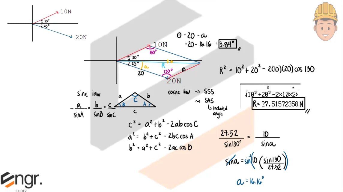
Using the Law of Sines,
$$ \frac{d}{\sin 40^\circ}=\frac{1}{\sin 100^\circ} $$ $$ d=\frac{\sin 40^\circ}{\sin 100^\circ}(1)=0.6527\text{ m} $$Substitute the value of \(d\) into the moment equation.
$$ 250(1)-600(0.6527)+F(0.6527)=400 $$ $$ 250-391.62+0.6527F=400 $$ $$ 0.6527F=541.62 $$ $$ F=\frac{541.62}{0.6527} $$ $$ F=829.82\text{ N} $$ $$ \boxed{F\approx 830\text{ N}} $$

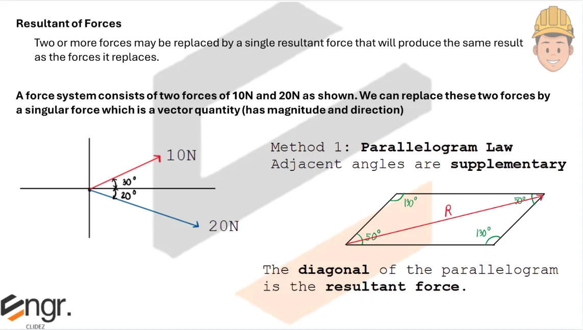
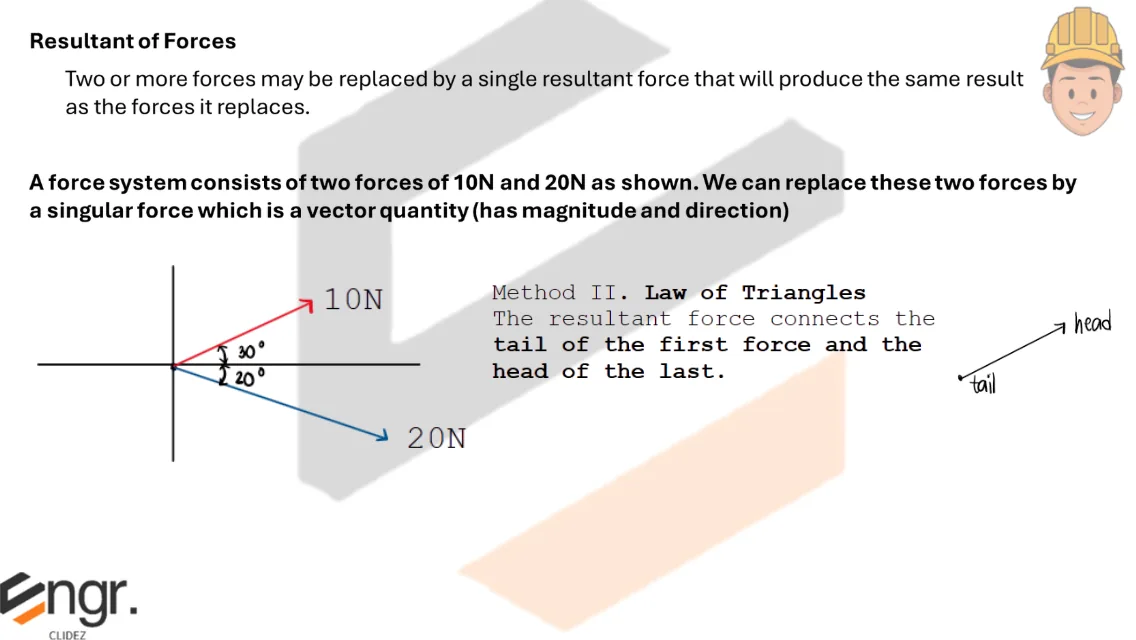
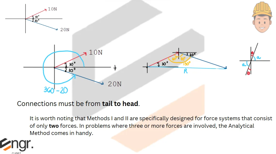
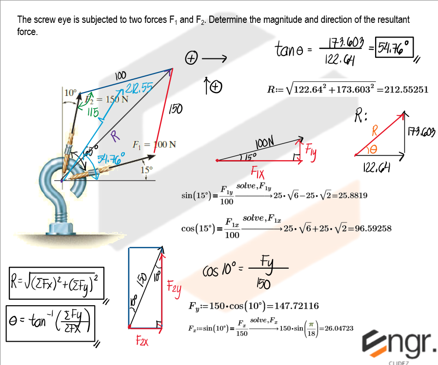
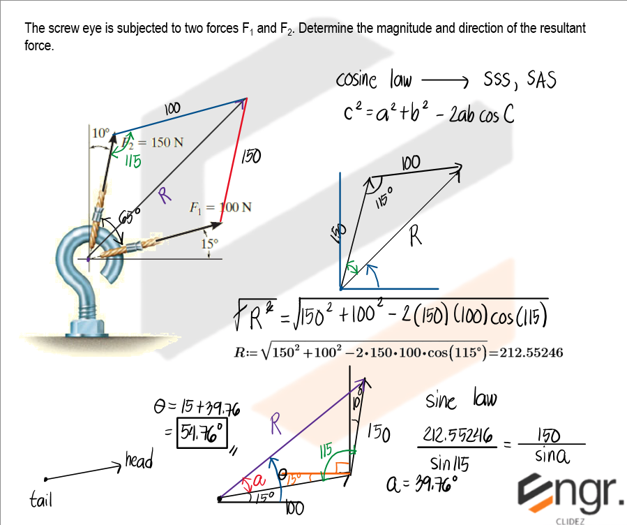
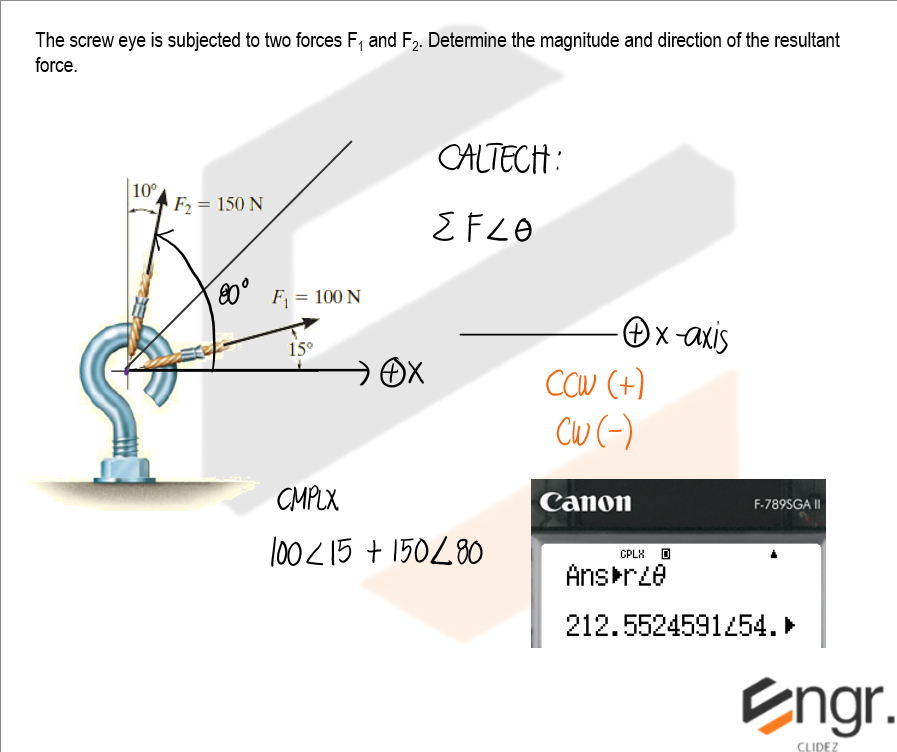
The screw eye is subjected to two forces F1 and F2. Determine the magnitude and direction of the resultant force.
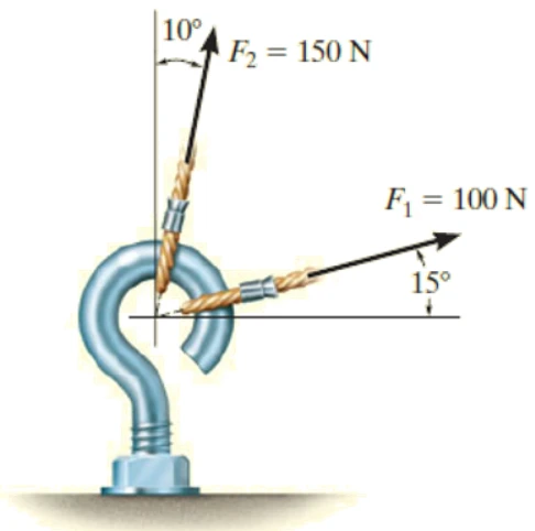
See images:
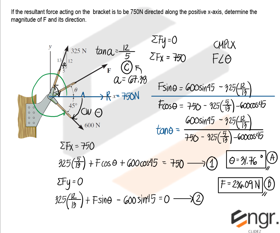
If the resultant force acting on the bracket is to be 750 N directed along the positive x-axis, determine the magnitude of F and its direction.
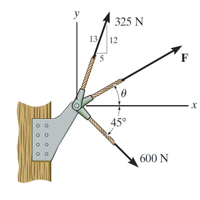
See images:
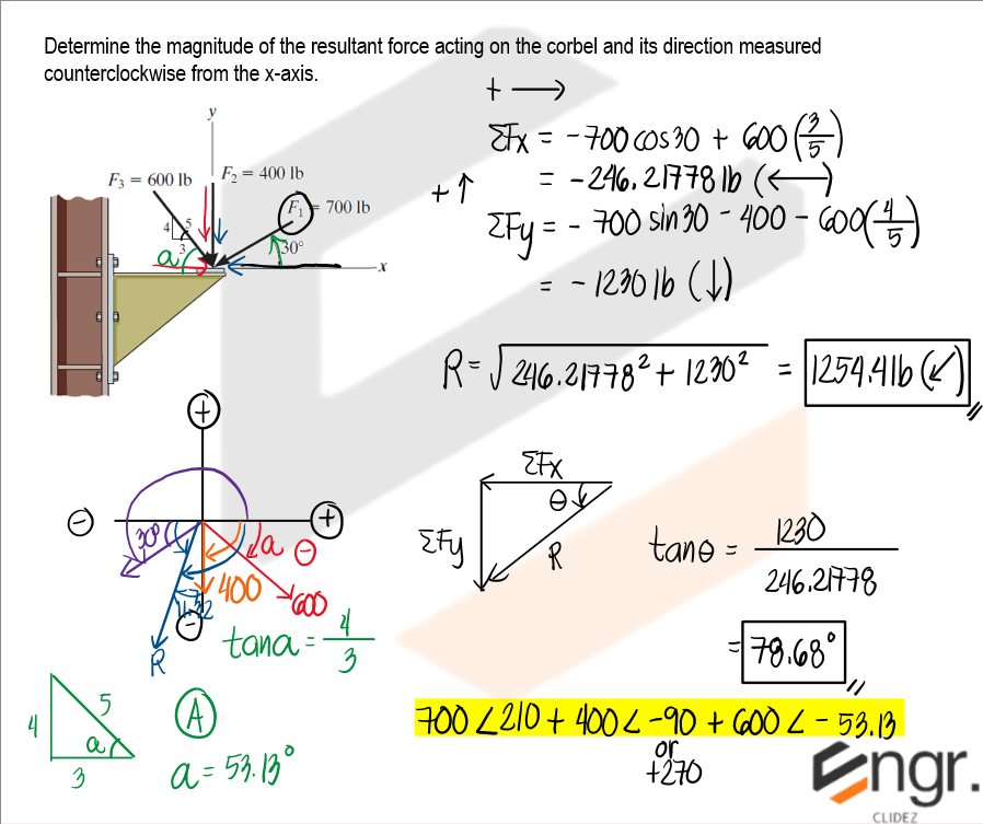
Determine the magnitude of the resultant force acting on the corbel and its direction measured counterclockwise from the x-axis.
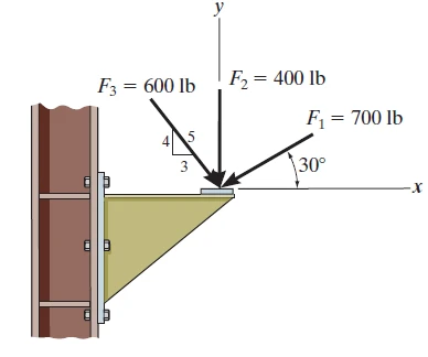
See images:
Two forces act at a pin: 8kN to the right and 6kN acting 60° above the positive x-axis. Determine the magnitude and direction of the resultant.
Resolve each force into rectangular components, then combine the components.
Forces of 5kN east, 7kN at 120° from the positive x-axis, and 4kN downward act at the same point. Find the resultant force.
Add x-components and y-components with signs.
A 10kN force acts 20° above the positive x-axis. A second force P acts 150° from the positive x-axis. Determine P so that the resultant is vertical, then compute the resultant magnitude.
For the resultant to be vertical, the horizontal components must cancel.
Additional board-style practice items for this topic.
If the system shown is in equilibrium,
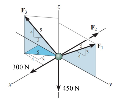
What is the value of F1?
What is the value of F2?
What is the value of F3?
Solution pending in psadquestions/q25.json.
CE Board 2011
An eyebolt is subjected to three forces, A, B, and C, where A=6kN, B=2.4kN, and ϴ=30º.
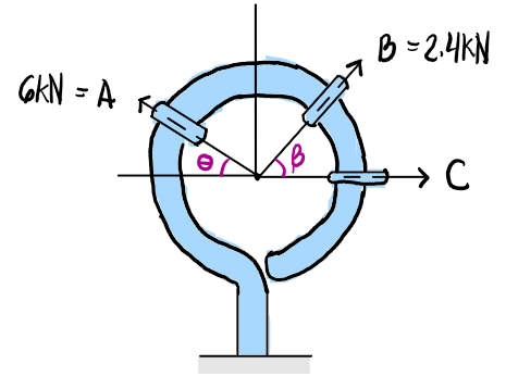
Determine the angle β if the resultant of the three forces acts along the y-axis if C=4.6kN.
What is the resultant of the forces if C=4.6kN and β=45º?
Determine the force, C, if the resultant is 7kN acting along the x-axis and β=45º.
Solution pending in psadquestions/q52.json.
A force F= 50 N is acting horizontally, and another force P = 60 N is acting upward and to the right. If the resultant of these two forces is 90 N, compute the horizontal component of the resultant in Newtons.
Answer:
Solution pending in psadquestions/q552.json.
A 30N force is acting upward and a 40N force is acting to the right. Compute the magnitude of the third force required for translation equilibrium.
Answer:
Solution pending in psadquestions/q561.json.
Two guy wires are attached to an anchor ring: T1 = 7 kN at 15° and T2 = 3.5 kN at 30°.
Calculate the magnitude of the resultant force.
Determine the angle of the resultant force from Question 31 with respect to the horizontal axis.
For the anchor ring in Question 31, determine the concrete block weight W required to prevent uplift using a factor of safety of 1.25.
Part 1.
Resolve the two tensions into perpendicular components. Taking the horizontal components opposite in sense:Part 2.
Use the resultant components from the previous item:Part 3.
The uplift to be resisted is the vertical component of the resultant:A hook is subjected to forces A = 35 kN and B = 45 kN.
If the resultant is 80 kN acting along the positive x-axis, find the angle α.
If α = 60° for the hook in Question 37, find the value of force C such that the total resultant acts strictly along the x-axis.
For the hook forces A, B, and C to be in a state of static equilibrium, what is the required magnitude of force C?
Solution pending in psadquestions/t31.json.