CE Board Exam Randomizer

⬅ Back to Subject Topics

Force Systems and Components of Forces

Force systems are classified based on the spatial arrangement of the forces within the system. Coplanar force systems exist when all forces act within the same single two-dimensional plane. In contrast, non-coplanar force systems involve forces that do not all lie in the same plane; their lines of action extend in multiple dimensions. Concurrent force systems are those where the lines of action of all forces intersect at a common single point. Parallel force systems contain forces whose lines of action are parallel to one another, meaning they never intersect, regardless of whether they lie in the same plane or not. These classifications are distinct and can combine: you can have concurrent forces that are either coplanar or non-coplanar, and similarly for parallel forces. Understanding these basic arrangements is fundamental in statics and dynamics to determine conditions for equilibrium and resultant forces.

While a static paragraph and images can define these concepts, visualizing their spatial relationships is truly best achieved through interaction. The following tool allows you to dynamically explore each of these force system types, observing how changes in position and direction instantly transform the system's classification. Use the buttons to switch between systems, and toggle the highlighted XY, XZ, and YZ reference planes to see exactly how the forces sit in space.

Interactive 3D viewer — drag to orbit, scroll to zoom. Switch between force-system types and toggle the reference planes.

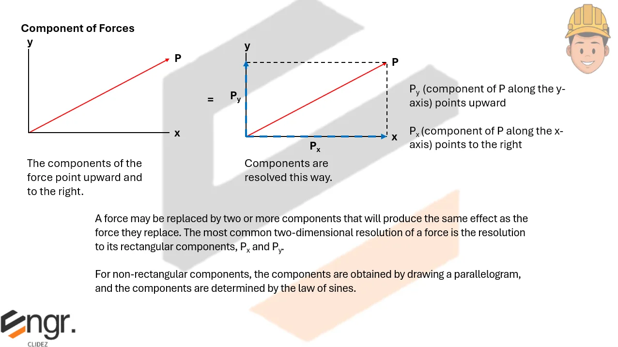
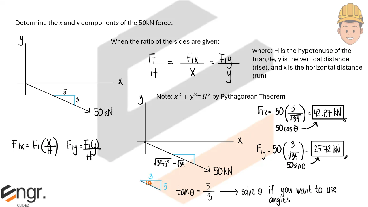
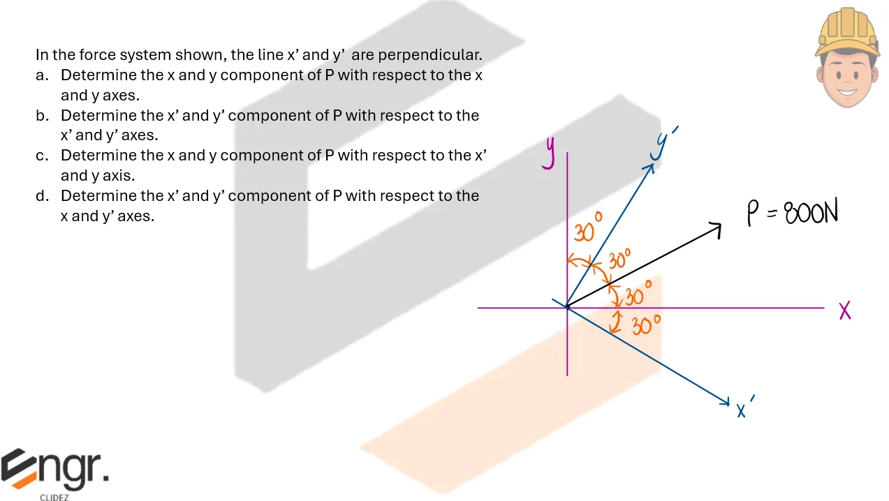
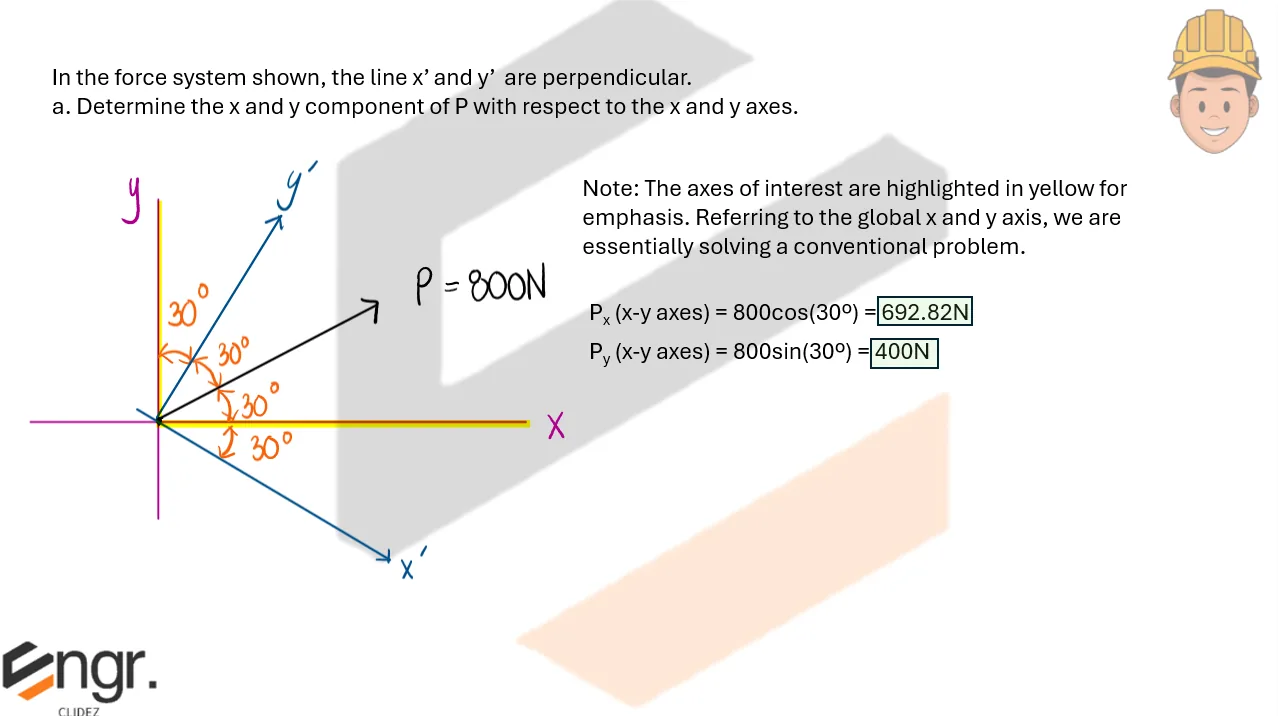
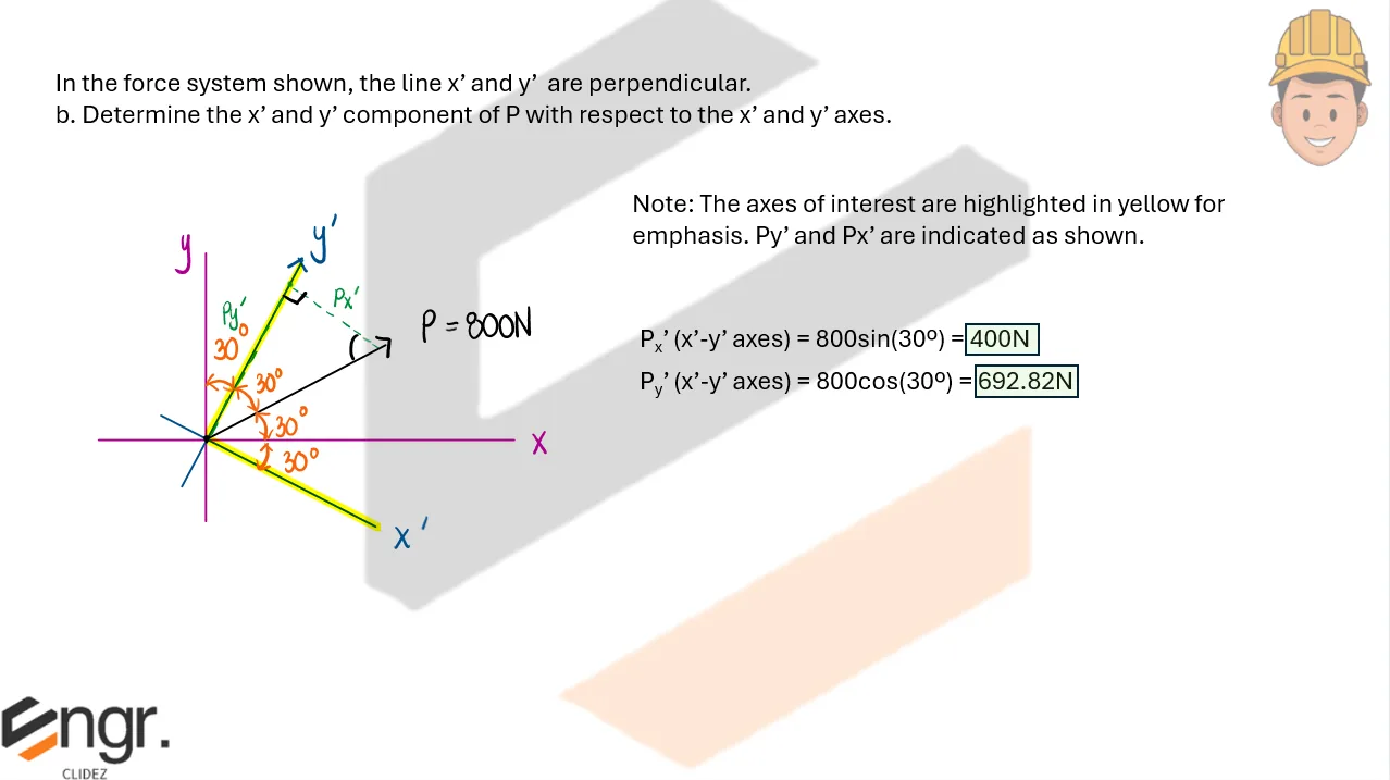
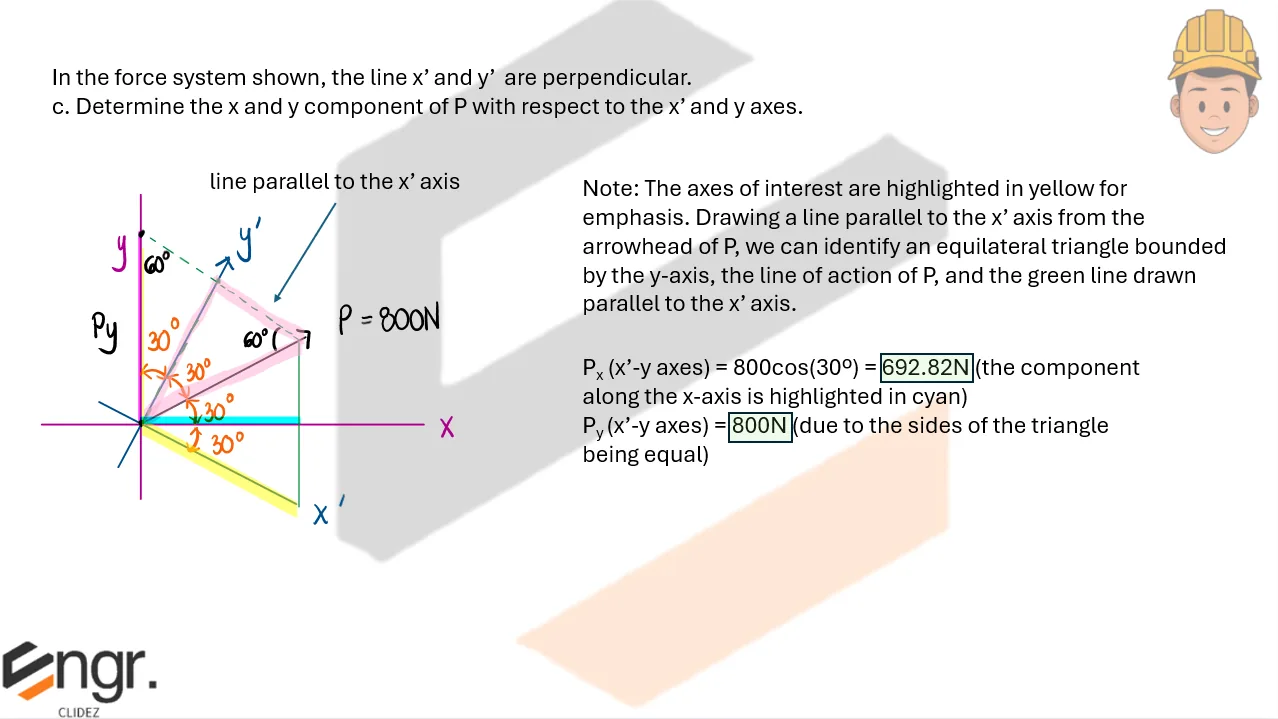
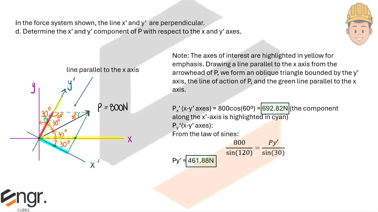
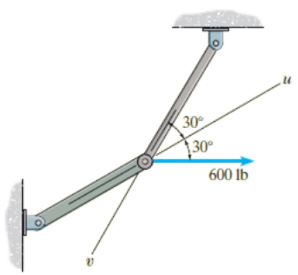
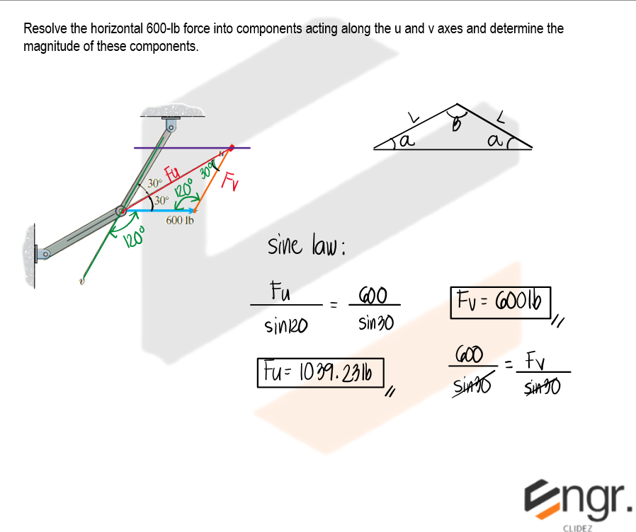
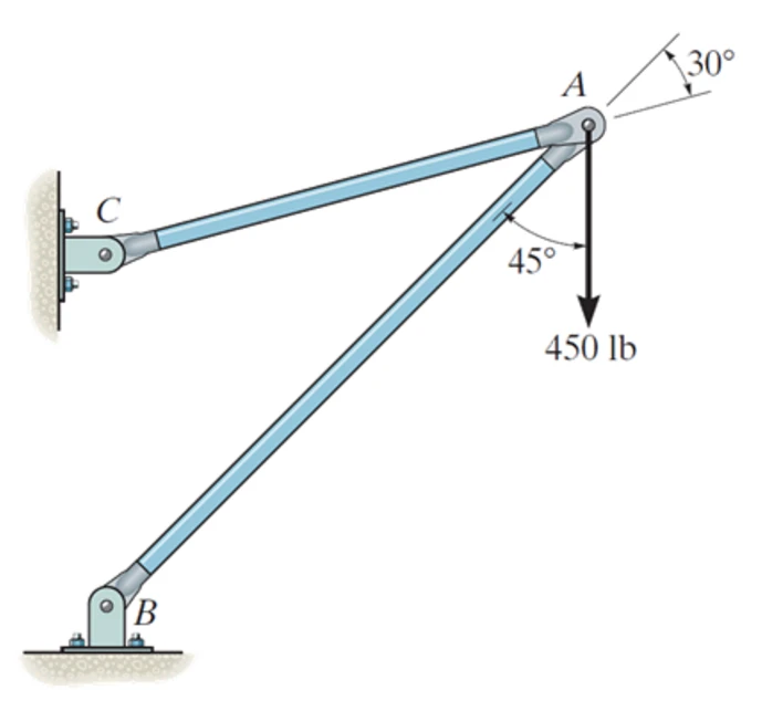
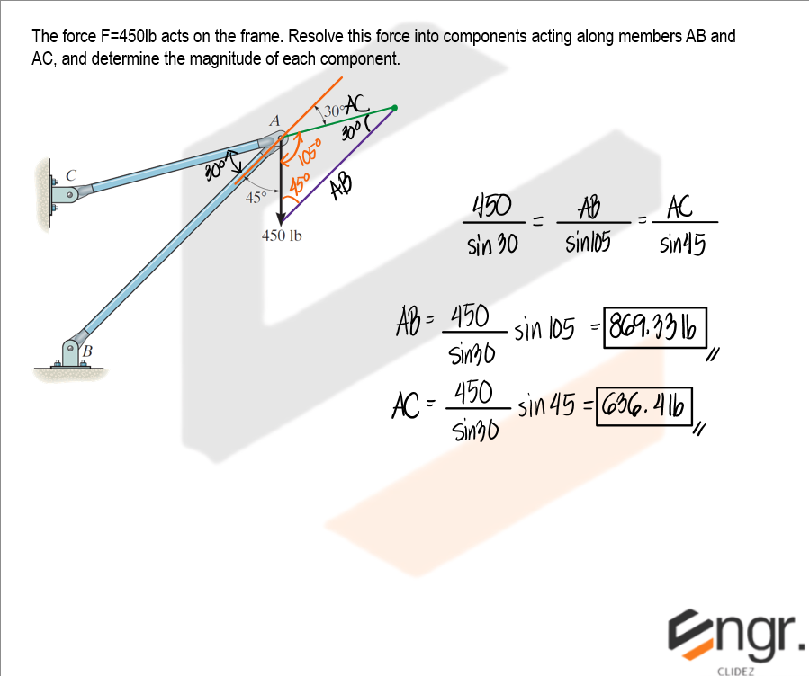
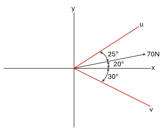
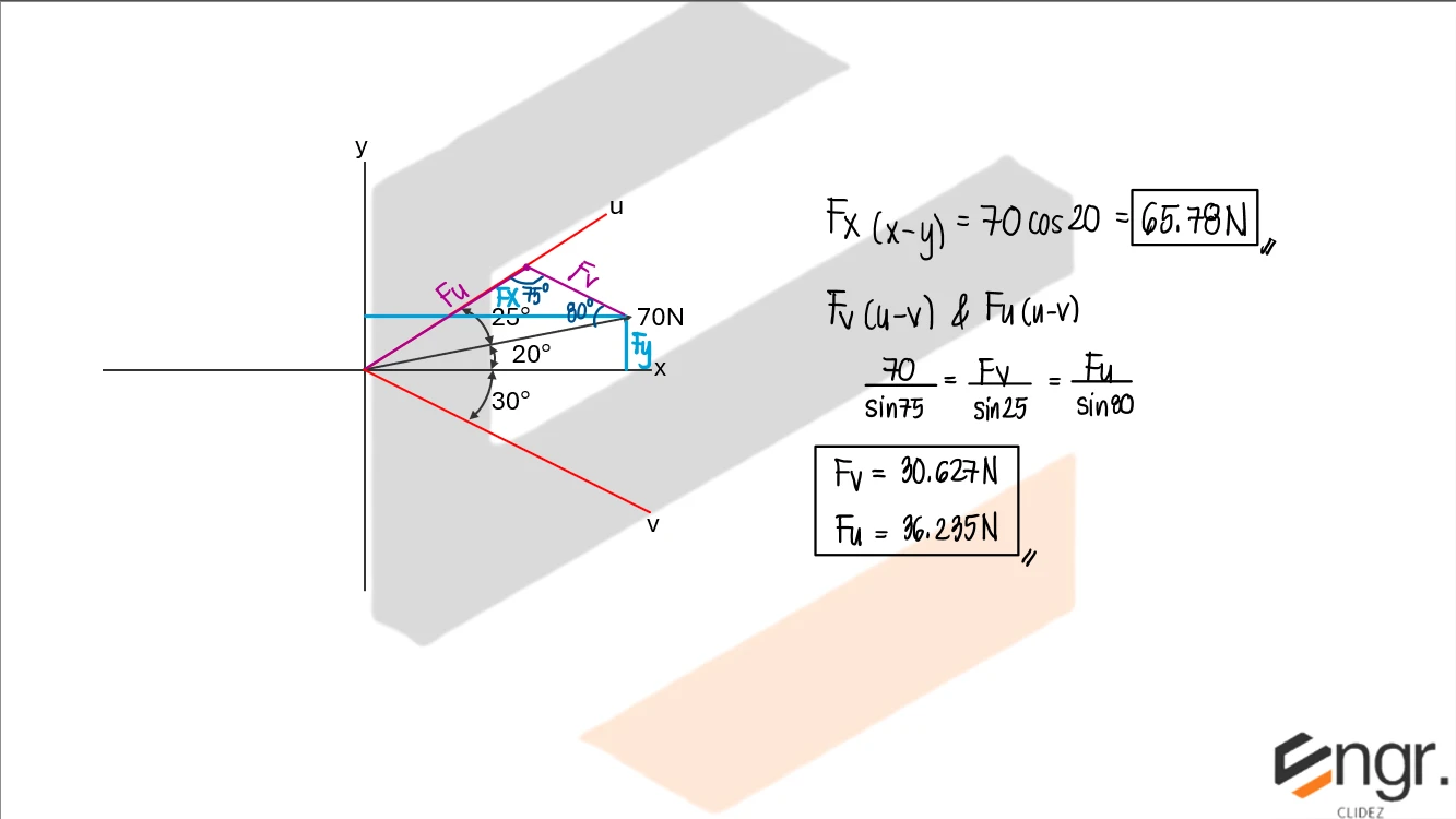
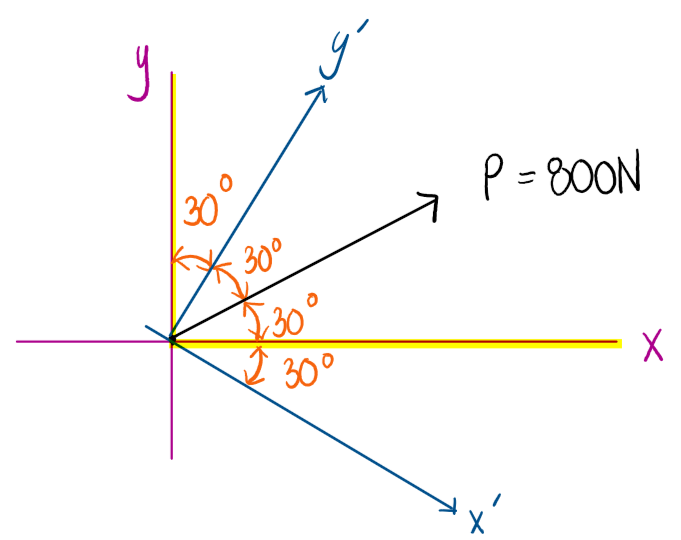
Once a force system is understood as a whole, the next step is to break each individual force into its parts. In engineering mechanics, analyzing the components of forces along an axis is essential for simplifying complex force systems. A force can be broken down into parts—called components—that act along specific directions, typically the horizontal (x) and vertical (y) axes. This allows engineers to analyze the effects of each component separately. When the axes are rotated—such as aligning them with an inclined plane or a structural member—the force components must be recalculated relative to the new orientation using trigonometric functions. This method is especially useful in structural and mechanical systems where forces do not align neatly with the standard coordinate axes. Understanding how to resolve forces along both original and rotated axes is fundamental for accurate equilibrium analysis, design, and safety assessment in real-world applications.

Diagram A Diagram B

Problem: Component of Forces Given the Angle

Refer to the image shown:

Diagram A Diagram B

See images:

Solution Diagram 1 Solution Diagram 2 Solution Diagram 3

Problem: Component of Forces Given the Ratios of the Sides):

Refer to the image shown:

Diagram A Diagram B

See images:

Solution Diagram 1 Solution Diagram 2 Solution Diagram 3

Problem: Component of Forces with Respect to Varying Axes

Refer to the image shown:

Diagram A Diagram B

See images:

Solution Diagram 1 Solution Diagram 2 Solution Diagram 3 Solution Diagram 3

Problem: Components Along Rotated Axes

If force F is to have a component along the u-axis of Fu = 6 kN, determine the magnitude of F and the magnitude of its component Fv along the v-axis.

Problem Figure 2

See images:

Solution Diagram 4

Problem: Components Along Rotated Axes

Resolve the horizontal 600-lb force into components acting along the u and v axes and determine the magnitude of these components.

Problem Figure 2

See images:

Solution Diagram 5

Problem: Components Along Rotated Axes

The force F = 450 lb acts on the frame. Resolve this force into components acting along members AB and AC, and determine the magnitude of each component.

Problem Figure 2

See images:

Solution Diagram 6

Problem: Component of a Force along Inclined Axes u and v

a. Determine the component of the 70N load along x with respect to the x and y-axes.
b. Determine the component of the 70N load along u and with respect to the u and v-axes.

Problem Figure 1

See images:

Solution Diagram 1
Scroll to zoom

Exam Generator Problems

Additional board-style practice items for this topic.

Question Bank: q325

PSAD - Statics / Component of Forces / Engr. Janclyde Espinosa (Clidez)

In the force system shown, the lines x' and y' are perpendicular.

q325

Determine the x and y component of P with respect to the x and y axes, respectively.

  1. 692.82, 400
  2. 400, 692.82
  3. 692.82, 800
  4. 692.82, 461.88

Determine the x' and y' component of P with respect to the x' and y' axes, respectively.

  1. 400, 692.82
  2. 692.82, 400
  3. 692.82, 800
  4. 692.82, 461.88

Determine the x and y component of P with respect to the x' and y axes, respectively.

  1. 692.82, 800
  2. 692.82, 461.88
  3. 400, 692.82
  4. 692.82, 400

Determine the x' and y' component of P with respect to the x and y' axes, respectively.

  1. 692.82, 461.88
  2. 692.82, 800
  3. 400, 692.82
  4. 692.82, 400
The solution to this problem is already written within this page.