CE Board Exam Randomizer

⬅ Back to Subject Topics

Arches

Arches are used in construction to efficiently transfer loads to supports while allowing open spaces beneath. In this lecture, we focus on two common types: parabolic and circular arches. 
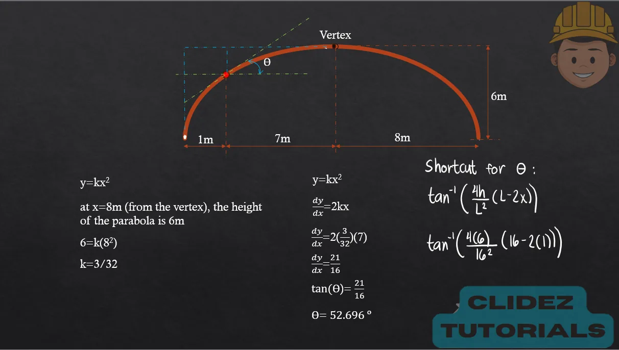
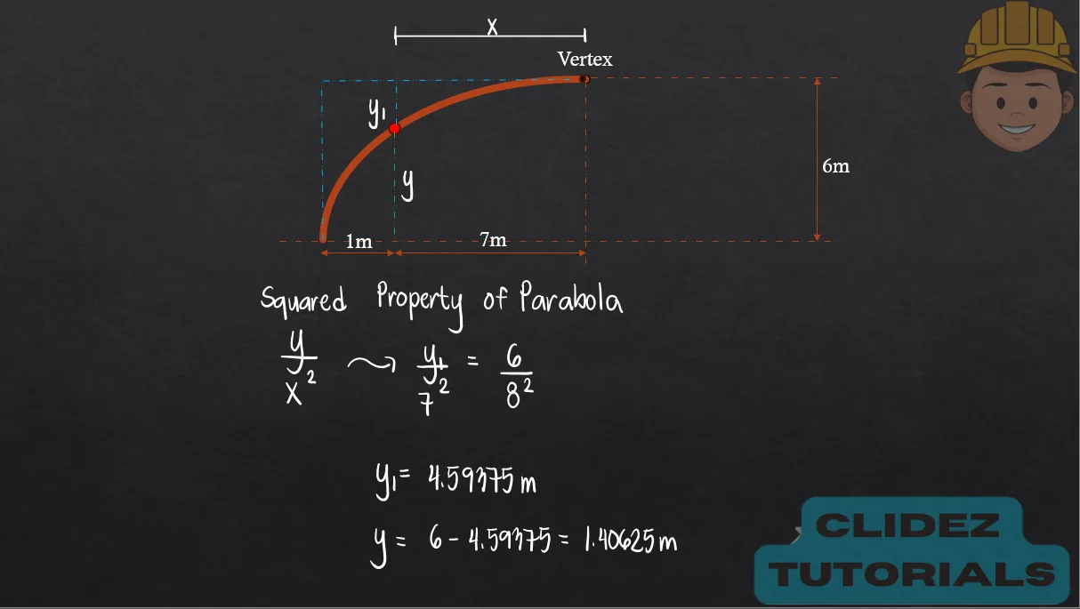
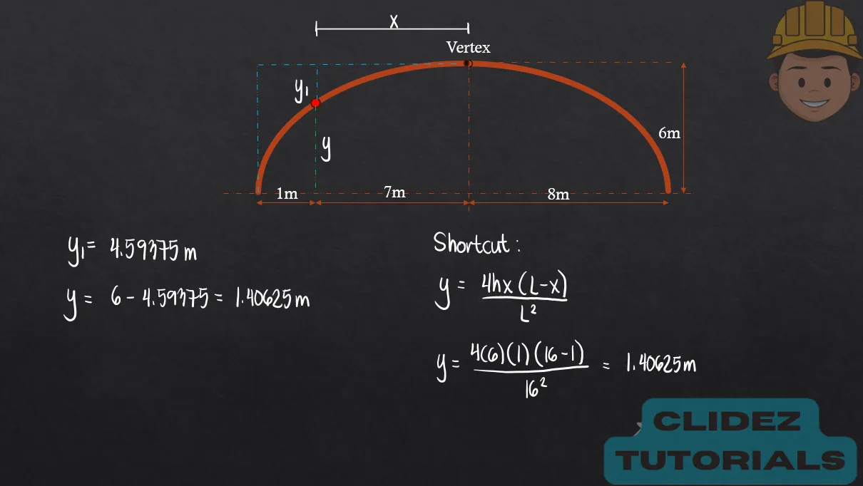
Parabolic arches are ideal for uniformly distributed loads, as their shape closely matches the natural thrust line, minimizing bending moments. They are commonly used in bridges and long-span roofs where load uniformity is expected. Circular arches, on the other hand, are easier to construct and are often used in shorter spans or when aesthetics and tradition are prioritized, like in masonry arches or historical structures. However, they tend to generate higher bending moments under non-uniform loading. Understanding their structural behavior helps engineers choose the most efficient arch type based on span, load condition, material, and construction practicality.

    Equation for Arch Profile (Parabolic Arch):
$$ y = \frac{4hx(L - x)}{L^2} $$
    Shortcut Formula for Arch Slope:
$$ \theta = \tan^{-1} \left( \frac{4h}{L^2}(L - 2x) \right) $$
Concept Concept Concept Concept Concept Concept Concept Concept Concept Concept

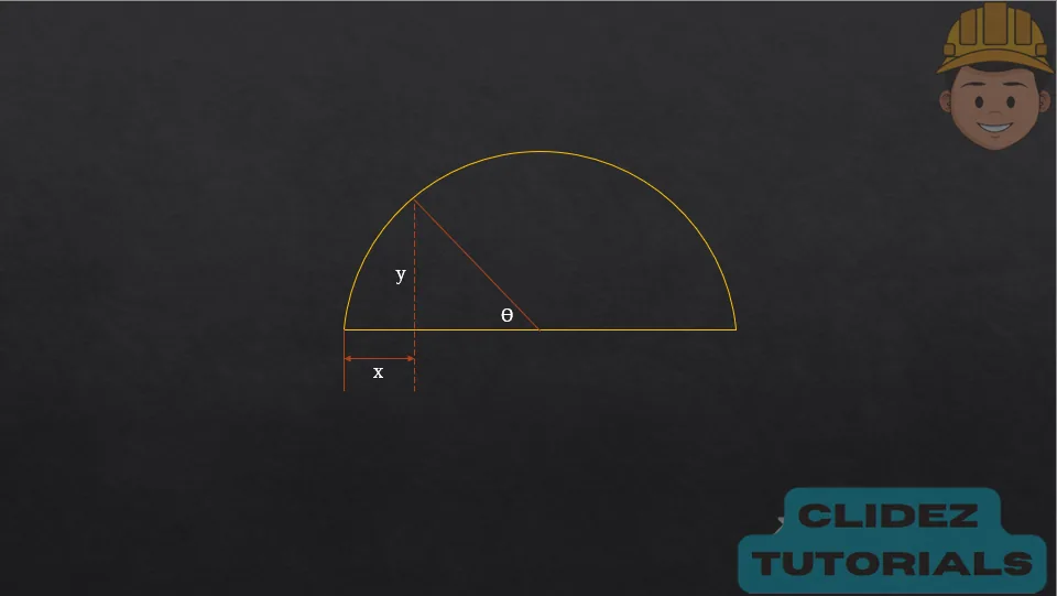
In the case of a circular arch, especially a semicircular arch, the method of analysis still follows the principles of static equilibrium. However, the geometry is based on circular coordinates. Referring to the diagram, if the radius of the arch is R and the angle $\theta$ is measured from the vertical, the coordinates of a point on the arch are:

$$ x = R - R \cos \theta $$
$$ y = R \sin \theta $$
These equations locate points along the top half of a vertical circle, starting from the crown ($theta=0 º$) down to the springing points ($theta=90 º$). While the analysis steps for internal forces are similar to those of parabolic arches, the curvature causes non-zero bending moments even under uniform loading, since the circular shape does not naturally follow the thrust line.

Concept

Problem:

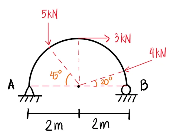
In the figure shown, $\theta=$ 30º and $\beta=$ 45°. The radius of the arch is 1m.
a. Determine the resultant of the three forces in kN. (4.90kN)
b. Determine the vertical reaction at B in kN. (2.14kN)
c. Determine the horizontal reaction at A in kN. (2.48kN)

Analysis of Arches | Statics of Rigid Bodies – Problem 1: – Diagram Analysis of Arches | Statics of Rigid Bodies – Problem 1: – Diagram Analysis of Arches | Statics of Rigid Bodies – Problem 1: – Diagram

See images:

Analysis of Arches | Statics of Rigid Bodies – Problem 1: – Diagram Analysis of Arches | Statics of Rigid Bodies – Problem 1: – Diagram Analysis of Arches | Statics of Rigid Bodies – Problem 1: – Diagram Analysis of Arches | Statics of Rigid Bodies – Problem 1: – Diagram

Problem:

Refer to the image shown:

Analysis of Arches | Statics of Rigid Bodies – Problem 2: – Diagram Analysis of Arches | Statics of Rigid Bodies – Problem 2: – Diagram Analysis of Arches | Statics of Rigid Bodies – Problem 2: – Diagram

See images:

Analysis of Arches | Statics of Rigid Bodies – Problem 2: – Diagram Analysis of Arches | Statics of Rigid Bodies – Problem 2: – Diagram Analysis of Arches | Statics of Rigid Bodies – Problem 2: – Diagram Analysis of Arches | Statics of Rigid Bodies – Problem 2: – Diagram

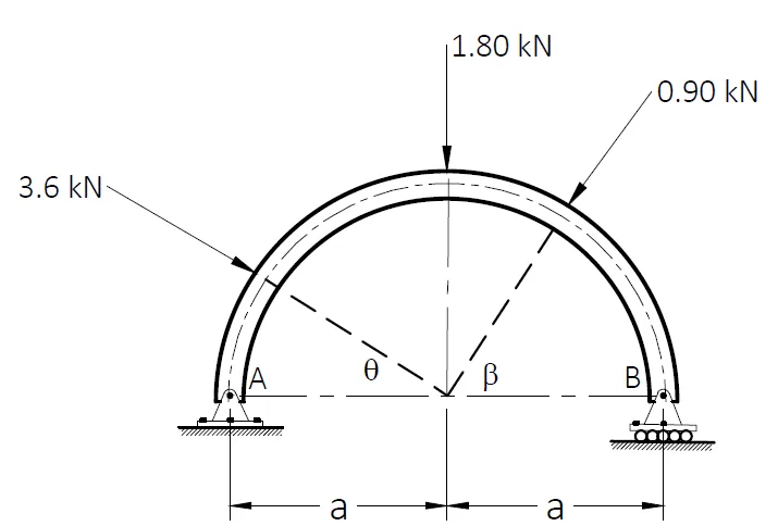
Problem: Arch Reactions and Moment Under Inclined Loads

For the arch shown below, use the following data: a = 1 m, P1 = 1.80 kN, P2 = 0.90 kN, P3 = 0.45 kN, θ = 30°, and β = 45°.

a. Which of the following most nearly gives the vertical reaction at B in kN?
A. 1.06
B. 2.10
C. 3.09
D. 1.59

b. Which of the following most nearly gives the horizontal reaction at B in kN?
A. 3.53
B. 1.78
C. 1.24
D. 2.48

c. Which of the following most nearly gives the moment in kN-m at the point where P1 is acting?
A. 0.53
B. 0.38
C. 0.84
D. 0.14

Analysis of Arches | Statics of Rigid Bodies – Problem 3: – Diagram Analysis of Arches | Statics of Rigid Bodies – Problem 3: – Diagram Analysis of Arches | Statics of Rigid Bodies – Problem 3: – Diagram

See images:

Analysis of Arches | Statics of Rigid Bodies – Problem 3: – Diagram Analysis of Arches | Statics of Rigid Bodies – Problem 3: – Diagram Analysis of Arches | Statics of Rigid Bodies – Problem 3: – Diagram Analysis of Arches | Statics of Rigid Bodies – Problem 3: – Diagram

Problem:

Refer to the image shown:

Analysis of Arches | Statics of Rigid Bodies – Problem 4: – Diagram Analysis of Arches | Statics of Rigid Bodies – Problem 4: – Diagram Analysis of Arches | Statics of Rigid Bodies – Problem 4: – Diagram

See images:

Analysis of Arches | Statics of Rigid Bodies – Problem 4: – Diagram Analysis of Arches | Statics of Rigid Bodies – Problem 4: – Diagram Analysis of Arches | Statics of Rigid Bodies – Problem 4: – Diagram Analysis of Arches | Statics of Rigid Bodies – Problem 4: – Diagram

Problem:

Refer to the image shown:

Analysis of Arches | Statics of Rigid Bodies – Problem 5: – Diagram Analysis of Arches | Statics of Rigid Bodies – Problem 5: – Diagram Analysis of Arches | Statics of Rigid Bodies – Problem 5: – Diagram

See images:

Analysis of Arches | Statics of Rigid Bodies – Problem 5: – Diagram Analysis of Arches | Statics of Rigid Bodies – Problem 5: – Diagram Analysis of Arches | Statics of Rigid Bodies – Problem 5: – Diagram Analysis of Arches | Statics of Rigid Bodies – Problem 5: – Diagram

Problem:

Refer to the image shown:

Analysis of Arches | Statics of Rigid Bodies – Problem 6: – Diagram Analysis of Arches | Statics of Rigid Bodies – Problem 6: – Diagram Analysis of Arches | Statics of Rigid Bodies – Problem 6: – Diagram

See images:

Analysis of Arches | Statics of Rigid Bodies – Problem 6: – Diagram Analysis of Arches | Statics of Rigid Bodies – Problem 6: – Diagram Analysis of Arches | Statics of Rigid Bodies – Problem 6: – Diagram Analysis of Arches | Statics of Rigid Bodies – Problem 6: – Diagram

Problem:

Refer to the image shown:

Analysis of Arches | Statics of Rigid Bodies – Problem 7: – Diagram Analysis of Arches | Statics of Rigid Bodies – Problem 7: – Diagram Analysis of Arches | Statics of Rigid Bodies – Problem 7: – Diagram

See images:

Analysis of Arches | Statics of Rigid Bodies – Problem 7: – Diagram Analysis of Arches | Statics of Rigid Bodies – Problem 7: – Diagram Analysis of Arches | Statics of Rigid Bodies – Problem 7: – Diagram Analysis of Arches | Statics of Rigid Bodies – Problem 7: – Diagram

Problem:

Refer to the image shown:

Analysis of Arches | Statics of Rigid Bodies – Problem 8: – Diagram Analysis of Arches | Statics of Rigid Bodies – Problem 8: – Diagram Analysis of Arches | Statics of Rigid Bodies – Problem 8: – Diagram

See images:

Analysis of Arches | Statics of Rigid Bodies – Problem 8: – Diagram Analysis of Arches | Statics of Rigid Bodies – Problem 8: – Diagram Analysis of Arches | Statics of Rigid Bodies – Problem 8: – Diagram Analysis of Arches | Statics of Rigid Bodies – Problem 8: – Diagram
-->

Problem (Three-hinged arch reactions):

A symmetric three-hinged arch has a span of 20m and a crown rise of 5m. A 40kN load acts at midspan at the crown hinge. Determine the vertical and horizontal reactions at each support.

By symmetry, the vertical reactions are equal. Take moments about the crown hinge for the left half.

\[ \begin{aligned} A_y&=B_y={40\over2}=20\ \text{kN} \\ \sum M_C=0:\quad H_A(5)-A_y(10)&=0 \\ H_A&=40\ \text{kN} \end{aligned} \] $\boxed{A_y=B_y=20\ \text{kN}},\qquad \boxed{H_A=H_B=40\ \text{kN}}$

Problem (Arch horizontal thrust under uniform load):

A parabolic three-hinged arch has a span of 30m, rise of 6m, and carries a uniform load of 8kN/m over the whole span. Determine the horizontal thrust.

For a parabolic arch with uniform load over the span, use the same horizontal thrust expression as the matching parabolic cable.

\[ \begin{aligned} H&={wL^2\over8h}={8(30)^2\over8(6)} \\ H&=150\ \text{kN} \end{aligned} \] $\boxed{H=150\ \text{kN}}$

Problem (Arch bending moment check):

At a section of an arch, the corresponding simply supported beam moment is 120kN-m. The horizontal thrust is 40kN and the vertical ordinate from the chord to the arch axis is 2m. Determine the bending moment at the section.

Use the arch moment relation M = M beam minus Hy.

\[ \begin{aligned} M_{arch}&=M_{beam}-Hy \\ M_{arch}&=120-40(2)=40\ \text{kN-m} \end{aligned} \] $\boxed{M_{arch}=40\ \text{kN-m}}$
Scroll to zoom

Exam Generator Problems

Additional board-style practice items for this topic.

Question Bank: q341

PSAD - Structural Theory / Analysis of Arches / Engr. Janclyde Espinosa (Clidez)

A circular arch is subjected to the given loads. The radius of the arch is 2m.

q341

Determine the moment at point B in N-m.

  1. 558
  2. 498
  3. 64
  4. 52

Compute the shear at point B just before the 800N load.

  1. 145
  2. 156
  3. 897
  4. 847

Compute the shear at point B just after the 800N load.

  1. 897
  2. 847
  3. 156
  4. 145

Compute the axial force at point B just before the 800N load.

  1. 399
  2. 105
  3. 125
  4. 364

Compute the axial force at point B just after the 800N load.

  1. 125
  2. 105
  3. 399
  4. 364

Compute the moment at E in N-m.

  1. 485
  2. 456
  3. 385
  4. 303

Compute the shear at point E in N.

  1. 1418
  2. 1425
  3. 1375
  4. 1396

Compute the axial force at point E in N.

  1. 105
  2. 94
  3. 112
  4. 132

Solution pending in psadquestions/q341.json.