CE Board Exam Randomizer

⬅ Back to Subject Topics

Forces in Space

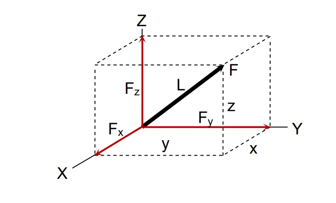
In the previous chapter, we focused our discussion on coplanar force systems—that is, forces in two dimensions. In this chapter, we extend our discussion to forces in three dimensions.

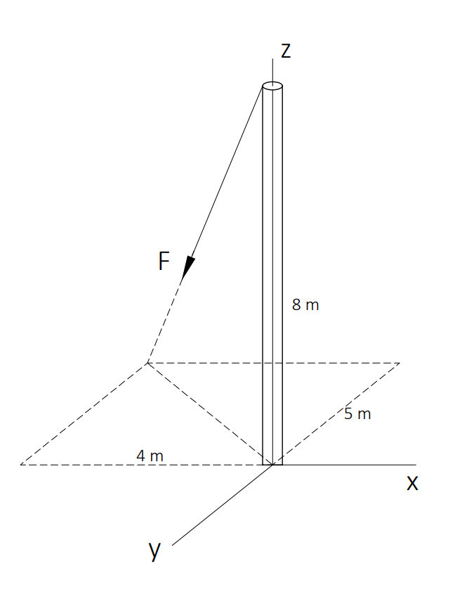
The figure below shows a force F in a three-dimensional system. The components of the force are proportional to the components of its distance from tail to head. In equation form, it is expressed as:

$$ \frac{F_x}{F} = \frac{x}{L} \quad \text{(1)} $$
$$ \frac{F_y}{F} = \frac{y}{L} \quad \text{(2)} $$
$$ \frac{F_z}{F} = \frac{z}{L} \quad \text{(3)} $$
Concept

Example 1: A force F = 340 kN has its tail at the origin and its head at the point (3, 5, 7).

Distance from Tail to Head:

$$ L = \sqrt{x^2 + y^2 + z^2} = \sqrt{3^2 + 5^2 + 7^2} = 9.11 $$

Component Calculations:

$$ F_x = \frac{3}{9.11} \cdot 340 = 111.96 \text{ kN} $$
$$ F_y = \frac{5}{9.11} \cdot 340 = 186.61 \text{ kN} $$
$$ F_z = \frac{7}{9.11} \cdot 340 = 261.25 \text{ kN} $$

Sign Convention:

Proper sign convention should be considered. Oppositely directed forces have opposite signs. The right-handed sign convention is commonly used:

Moment of a Force in Three-Dimensional System

We define a moment as the product of the magnitude of the force and the perpendicular distance from the line of action of the force to the point:

$$ M = F \cdot d $$

where \( d \) is the moment arm, the perpendicular distance.

The principle of moments still applies in three-dimensional force systems, and is expressed as:

$$ M_A = \sum \left( \mathbf{F} \times \mathbf{d} \right) $$

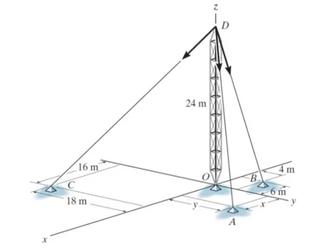
Problem: Vertical Member with Ball and Socket Support and Three Supporting Cables

A tower is held in place by a ball and socket support at its base and three cables attached at various points along its height. At the mid-height of the tower, a 70-kN lateral force acts along the negative x-axis. Note: The indicated x-axis in the figure is the positive x-axis.
Given:
x=18m
y=22m

Forces in Space (3D Systems) | Statics of Rigid Bodies – Problem 1: – Diagram Forces in Space (3D Systems) | Statics of Rigid Bodies – Problem 1: – Diagram Forces in Space (3D Systems) | Statics of Rigid Bodies – Problem 1: – Diagram

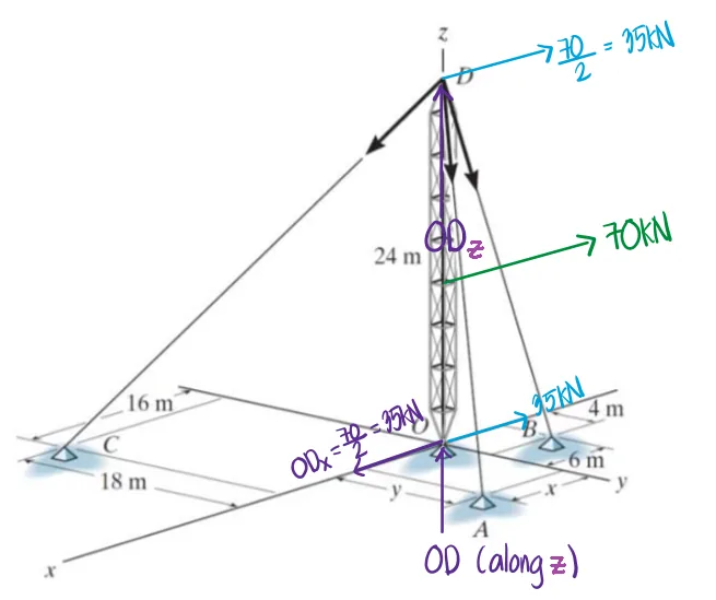
The 70-kN horizontal load is applied at the mid-height of the 24-m tower. For the free-body setup used here, translate it into equivalent joint forces shared by the top joint $D$ and the ball-and-socket support at $O$, so the horizontal force used at the top joint is $70/2=35$ kN.

Forces in Space (3D Systems) | Statics of Rigid Bodies – Problem 1: – Diagram

Use cable direction cosines from the top of the tower at $D$ to the ground anchors $C$, $A$, and $B$:

$$ \begin{aligned} L_{CD} &= \sqrt{16^2+18^2+24^2}=34 \text{ m} \\ L_{AD} &= \sqrt{18^2+22^2+24^2}=37.20215 \text{ m} \\ L_{BD} &= \sqrt{6^2+4^2+24^2}=25.05993 \text{ m} \end{aligned} $$

Let $CD$, $AD$, and $BD$ be the cable tensions, and let $OD$ be the vertical reaction at the support. Substituting the actual dimensions into the equilibrium equations:

$$ \begin{array}{l} \sum F_x=0 \\ 35-CD\left(\frac{16}{34}\right)-AD\left(\frac{18}{37.20215}\right)+BD\left(\frac{6}{25.05993}\right)=0 \\[8pt] \sum F_z=0 \\ -CD\left(\frac{24}{34}\right)-AD\left(\frac{24}{37.20215}\right)+BD\left(\frac{24}{25.05993}\right)+OD=0 \\[8pt] \sum F_y=0 \\ -CD\left(\frac{18}{34}\right)+AD\left(\frac{22}{37.20215}\right)+BD\left(\frac{4}{25.05993}\right)=0 \end{array} $$

Due to the direction of the lateral load, cable $BD$ would tend to shorten and go into compression in the trial equilibrium setup. Since a cable can carry tension only and cannot resist compression, set:

$$BD=0$$

Solving with $BD=0$, the equilibrium equations reduce to:

$$ \begin{array}{l} \sum F_x=0 \\ 35-CD\left(\frac{16}{34}\right)-AD\left(\frac{18}{37.20215}\right)=0 \\[8pt] \sum F_z=0 \\ -CD\left(\frac{24}{34}\right)-AD\left(\frac{24}{37.20215}\right)+OD=0 \\[8pt] \sum F_y=0 \\ -CD\left(\frac{18}{34}\right)+AD\left(\frac{22}{37.20215}\right)=0 \end{array} $$

From these equations:

$$ \begin{bmatrix} CD\\ AD\\ BD\\ OD \end{bmatrix} = \begin{bmatrix} 38.72781\\ 34.67064\\ 0\\ 49.70414 \end{bmatrix} \text{ kN} $$

The ball-and-socket support has a vertical component $OD=49.70414$ kN and a horizontal component equal to the translated joint load, $35$ kN. Thus the resultant support reaction is:

$$ R_{OD}=\sqrt{49.70414^2+35^2}=60.79064 \text{ kN} $$
$$ \boxed{CD=38.73\text{ kN}},\quad \boxed{AD=34.67\text{ kN}},\quad \boxed{BD=0},\quad \boxed{R_{OD}=60.79\text{ kN}} $$
Forces in Space (3D Systems) | Statics of Rigid Bodies – Problem 1: – Diagram Forces in Space (3D Systems) | Statics of Rigid Bodies – Problem 1: – Diagram Forces in Space (3D Systems) | Statics of Rigid Bodies – Problem 1: – Diagram

Problem:

Refer to the image shown:

Forces in Space (3D Systems) | Statics of Rigid Bodies – Problem 2: – Diagram Forces in Space (3D Systems) | Statics of Rigid Bodies – Problem 2: – Diagram Forces in Space (3D Systems) | Statics of Rigid Bodies – Problem 2: – Diagram

See images:

Forces in Space (3D Systems) | Statics of Rigid Bodies – Problem 2: – Diagram Forces in Space (3D Systems) | Statics of Rigid Bodies – Problem 2: – Diagram Forces in Space (3D Systems) | Statics of Rigid Bodies – Problem 2: – Diagram Forces in Space (3D Systems) | Statics of Rigid Bodies – Problem 2: – Diagram

Problem:

Refer to the image shown:

Forces in Space (3D Systems) | Statics of Rigid Bodies – Problem 3: – Diagram Forces in Space (3D Systems) | Statics of Rigid Bodies – Problem 3: – Diagram Forces in Space (3D Systems) | Statics of Rigid Bodies – Problem 3: – Diagram

See images:

Forces in Space (3D Systems) | Statics of Rigid Bodies – Problem 3: – Diagram Forces in Space (3D Systems) | Statics of Rigid Bodies – Problem 3: – Diagram Forces in Space (3D Systems) | Statics of Rigid Bodies – Problem 3: – Diagram Forces in Space (3D Systems) | Statics of Rigid Bodies – Problem 3: – Diagram

Problem:

Refer to the image shown:

Forces in Space (3D Systems) | Statics of Rigid Bodies – Problem 4: – Diagram Forces in Space (3D Systems) | Statics of Rigid Bodies – Problem 4: – Diagram Forces in Space (3D Systems) | Statics of Rigid Bodies – Problem 4: – Diagram

See images:

Forces in Space (3D Systems) | Statics of Rigid Bodies – Problem 4: – Diagram Forces in Space (3D Systems) | Statics of Rigid Bodies – Problem 4: – Diagram Forces in Space (3D Systems) | Statics of Rigid Bodies – Problem 4: – Diagram Forces in Space (3D Systems) | Statics of Rigid Bodies – Problem 4: – Diagram

Problem:

Refer to the image shown:

Forces in Space (3D Systems) | Statics of Rigid Bodies – Problem 5: – Diagram Forces in Space (3D Systems) | Statics of Rigid Bodies – Problem 5: – Diagram Forces in Space (3D Systems) | Statics of Rigid Bodies – Problem 5: – Diagram

See images:

Forces in Space (3D Systems) | Statics of Rigid Bodies – Problem 5: – Diagram Forces in Space (3D Systems) | Statics of Rigid Bodies – Problem 5: – Diagram Forces in Space (3D Systems) | Statics of Rigid Bodies – Problem 5: – Diagram Forces in Space (3D Systems) | Statics of Rigid Bodies – Problem 5: – Diagram

Problem:

Refer to the image shown:

Forces in Space (3D Systems) | Statics of Rigid Bodies – Problem 6: – Diagram Forces in Space (3D Systems) | Statics of Rigid Bodies – Problem 6: – Diagram Forces in Space (3D Systems) | Statics of Rigid Bodies – Problem 6: – Diagram

See images:

Forces in Space (3D Systems) | Statics of Rigid Bodies – Problem 6: – Diagram Forces in Space (3D Systems) | Statics of Rigid Bodies – Problem 6: – Diagram Forces in Space (3D Systems) | Statics of Rigid Bodies – Problem 6: – Diagram Forces in Space (3D Systems) | Statics of Rigid Bodies – Problem 6: – Diagram

Problem:

Refer to the image shown:

Forces in Space (3D Systems) | Statics of Rigid Bodies – Problem 7: – Diagram Forces in Space (3D Systems) | Statics of Rigid Bodies – Problem 7: – Diagram Forces in Space (3D Systems) | Statics of Rigid Bodies – Problem 7: – Diagram

See images:

Forces in Space (3D Systems) | Statics of Rigid Bodies – Problem 7: – Diagram Forces in Space (3D Systems) | Statics of Rigid Bodies – Problem 7: – Diagram Forces in Space (3D Systems) | Statics of Rigid Bodies – Problem 7: – Diagram Forces in Space (3D Systems) | Statics of Rigid Bodies – Problem 7: – Diagram

Problem:

Refer to the image shown:

Forces in Space (3D Systems) | Statics of Rigid Bodies – Problem 8: – Diagram Forces in Space (3D Systems) | Statics of Rigid Bodies – Problem 8: – Diagram Forces in Space (3D Systems) | Statics of Rigid Bodies – Problem 8: – Diagram

See images:

Forces in Space (3D Systems) | Statics of Rigid Bodies – Problem 8: – Diagram Forces in Space (3D Systems) | Statics of Rigid Bodies – Problem 8: – Diagram Forces in Space (3D Systems) | Statics of Rigid Bodies – Problem 8: – Diagram Forces in Space (3D Systems) | Statics of Rigid Bodies – Problem 8: – Diagram

Problem (3D force vector from two points):

A 600N cable force acts from A(0, 0, 0) toward B(2, 3, 6)m. Express the force in vector form.

Form the unit vector from A to B, then multiply by the force magnitude.

\[ \begin{aligned} L&=\sqrt{2^2+3^2+6^2}=7 \\ \hat{u}_{AB}&={2\over7}\mathbf{i}+{3\over7}\mathbf{j}+{6\over7}\mathbf{k} \\ \mathbf{F}&=171.4\mathbf{i}+257.1\mathbf{j}+514.3\mathbf{k}\ \text{N} \end{aligned} \] $\boxed{\mathbf{F}=171.4\mathbf{i}+257.1\mathbf{j}+514.3\mathbf{k}\ \text{N}}$

Problem (Magnitude of a 3D force):

A force has components Fx = 120N, Fy = -90N, and Fz = 160N. Determine its magnitude and coordinate direction angle with the positive z-axis.

Use the 3D magnitude formula and the direction cosine for the z-axis.

\[ \begin{aligned} F&=\sqrt{120^2+(-90)^2+160^2}=219.3\ \text{N} \\ \cos\gamma&={160\over219.3}=0.7297 \\ \gamma&=43.1^\circ \end{aligned} \] $\boxed{F=219.3\ \text{N}},\qquad \boxed{\gamma=43.1^\circ}$

Problem (Moment of a 3D force about the origin):

A force F = 40i + 20j - 30k N is applied at point r = 2i - 1j + 3k m. Determine the moment about the origin.

Compute the cross product r cross F.

\[ \begin{aligned} \mathbf{M}_O&=\mathbf{r}\times\mathbf{F} \\ &=\begin{vmatrix}\mathbf{i}&\mathbf{j}&\mathbf{k}\\2&-1&3\\40&20&-30\end{vmatrix} \\ &=-30\mathbf{i}+180\mathbf{j}+80\mathbf{k}\ \text{N-m} \end{aligned} \] $\boxed{\mathbf{M}_O=-30\mathbf{i}+180\mathbf{j}+80\mathbf{k}\ \text{N-m}}$
Scroll to zoom

Exam Generator Problems

Additional board-style practice items for this topic.

Question Bank: q129

PSAD - Statics / Forces in Space / Engr. Janclyde Espinosa (Clidez)

A 3500-N stoplight shown is connected to three cables and hangs mid-air.

q129

Which of the following most nearly gives the tension at cable A in Newtons?

  1. 1596
  2. 1771
  3. 1479
  4. 1372

Which of the following most nearly gives the tension at cable B in Newtons?

  1. 1411
  2. 1201
  3. 1393
  4. 1288

Which of the following most nearly gives the tension at cable C in Newtons?

  1. 2804
  2. 2781
  3. 2620
  4. 2447

Solution pending in psadquestions/q129.json.

Question Bank: q146

PSAD - Statics / Forces in Space (3D) / Engr. Janclyde Espinosa (Clidez)

A pole shown is acted on by a force F.

q146

If F = 50kN, compute its component (in kN) along the x-axis

  1. 19.50
  2. 17.40
  3. 21.25
  4. 24.20

If the force along x-axis is 20kN, compute the value of the force F in kN

  1. 51.20
  2. 46.70
  3. 54.10
  4. 63.80

If Fx=20kN, Fy =24kN, and Fz=39kn, compute the height of the pole in meters.

  1. 5.90
  2. 6.70
  3. 7.20
  4. 5.40

Solution pending in psadquestions/q146.json.