Compression Members
Compression members are elements that carry primarily axial compressive forces. The most common example in buildings and bridges is the column (wooden versions are often called posts). Shorter or non-column members in compression may be called struts or compression blocks; bracing at column and roof joints can also resist compression. Some truss members act in compression.
The actual (applied) compressive stress is:
Euler's Column Theory
For a long, slender member loaded axially, a gradually increased load will eventually cause instability and lateral deflection—buckling. The corresponding load is the critical buckling load. If the member is stockier, a larger load is needed to reach instability; extremely stocky members may fail by compressive yielding instead of buckling.
Buckling strength depends on slenderness. Euler's critical load is:
Expressed using slenderness ratio $L/r$:
The corresponding critical buckling stress is:
Limitations of Euler's Formula
- If $P/A$ exceeds the proportional limit of the material, Euler's formula is not applicable.
- If $L/r < 100$, Euler's formula is invalid; the proportional limit then controls the critical stress $P/A$.

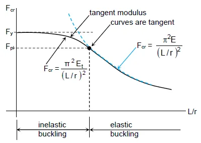
Inelastic Buckling (Tangent Modulus)
When the stress at buckling is above the proportional limit, the stress→strain curve is nonlinear and the elastic modulus $E$ is no longer appropriate. Replacing $E$ with the tangent modulus $E_t$ gives the inelastic buckling load:
Here, $E_t$ is the slope of the stress→strain curve between the proportional limit $F_{pl}$ and yield strength $F_y$.
The column strength curve depicts the compressive strength of a column for a given material. Aside from the material properties $F_y$, $E$, and $E_t$, the strength depends primarily on the slenderness ratio $L/r$.
Summary of Formulas
Slenderness Ratio (SR)
Euler's Critical Buckling Load
Euler's Critical Buckling Stress
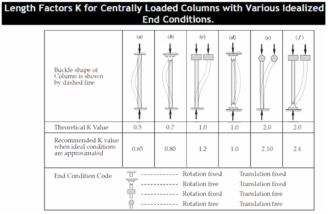
Effective Length Factors
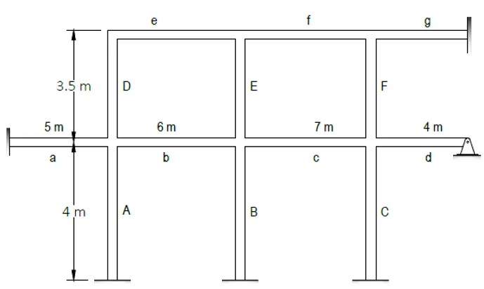
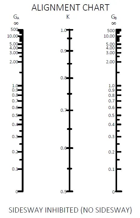
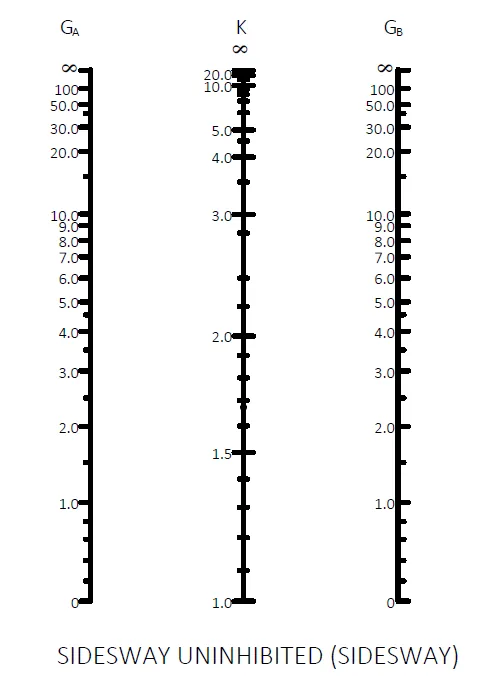
For alignment-chart problems, the end-restraint stiffness ratio compares the columns meeting at a joint to the girders framing into that joint.
Alignment chart A is for continuous frames which are braced or not allowed to sway; that is, inhibited. Alignment chart B is for continuous frames which are allowed to sway; that is, uninhibited.
The subscripts A and B refer to the joints at the two ends of the column section being considered.
Where:
- Ic = moment of inertia of the column
- Lc = unsupported length of column
- Ig = moment of inertia of a girder or other restraining member
- Lg = unsupported length of a girder
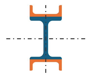
The moment of inertia Ic and Ig are taken about the axis perpendicular to the plane of buckling being considered.
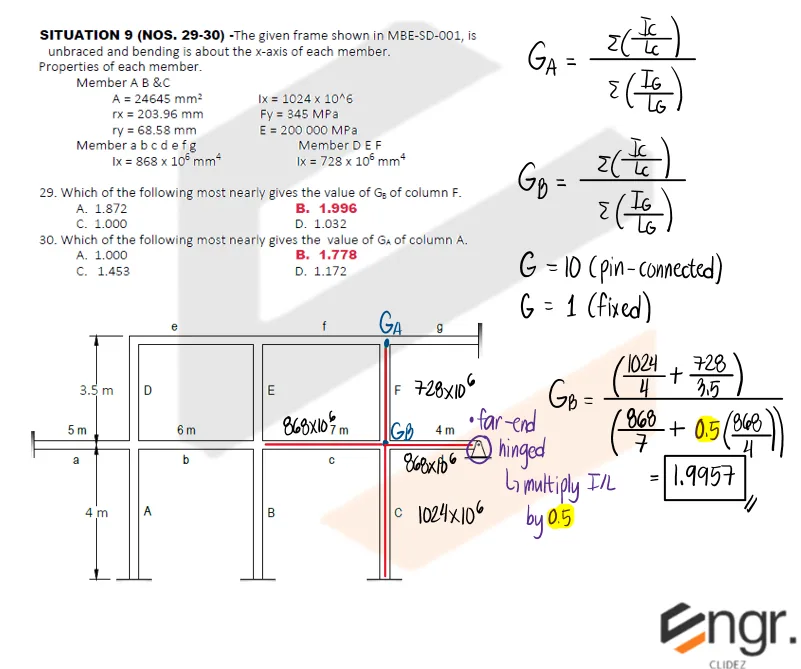
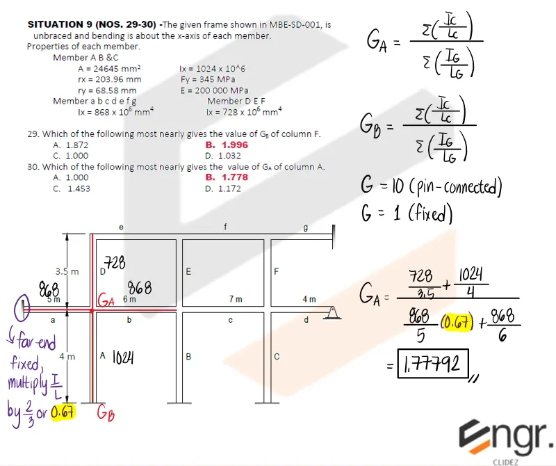
For a pinned-end column supported but not rigidly connected to a footing or foundation, G is theoretically infinity, but unless actually designed as a true friction-free pin, may be taken as 10 for practical design. If the column end is rigidly attached to a properly designed footing, G is theoretically zero but may be taken as 1.0. Smaller values may be used if justified by analysis.
Procedure for using alignment charts
- Calculate G values at each end of column.
- Enter alignment chart with value of G for the top of the column as GA.
- Enter alignment chart with value of G for the bottom of the column as GB.
- K factor is obtained at the point of intersection between the line connecting two G values and K line.
If a beam or girder is rigidly attached to a column, its stiffness should be multiplied by the appropriate factor as shown in the table, depending on the condition at the far end of the member.
Multipliers for Rigidly Attached Members
| Condition at Far End of Girder | Sidesway Prevented | Sidesway Uninhibited |
|---|---|---|
| Pinned | 1.50 | 0.50 |
| Fixed Against Rotation | 2.0 | 0.67 |
Old Code
A column is a compression member that is relatively slender compared to its length. Such members usually fail by buckling rather than crushing. Columns are generally classified into three groups:
1. Short Columns:
Failure occurs mainly by crushing, with no buckling involved.
2. Intermediate Columns:
Some fibers reach the yield stress, causing failure through a combination of crushing and buckling.
This type of behavior is considered elastic.
3. Long Columns:
Long columns usually buckle elastically, as their axial buckling stress remains below the proportional limit.
They typically fail by buckling or lateral bending.
The longer the column, the more prone it is to buckle, and the smaller the load it can support.
Buckling tendency is measured by the slenderness ratio, which is the ratio of the column length to its least radius of gyration.
Higher slenderness ratios correspond to lower load-carrying capacity.
Capacity of a Column
The axial capacity of a column is given by:
Where:
$A$ = cross-sectional area of the column
$F_a$ = allowable compressive stress
Critical Buckling Load
NSCP Formulas for Axially Loaded Columns
1. When $KL/r < C_c$ (Intermediate Column)
For axially loaded compression members with unbraced length ratios less than $C_c$, the allowable stress is:
Where:
Factor of safety:
2. When $KL/r > C_c$ (Long Column)
For slender columns where the slenderness ratio exceeds $C_c$, the allowable compressive stress is:
This is Euler's formula with a factor of safety of $\tfrac{23}{12} \approx 1.92$.
Definitions:
- $K$ = effective length factor
- $P$ = allowable axial load
- $A$ = cross-sectional area
- $F_a$ = allowable compressive stress
- $P = F_a A$
NSCP 2015 (ASD & LRFD) — Section 505: Design of Members for Compression
Design Compressive Strength
Where: $\phi_c = 0.9$ (LRFD), $\Omega_c = 1.67$ (ASD).
505.3 Compressive Strength of Flexural Buckling of Members Without Slender Elements
The nominal compressive strength, $P_n$, is based on the limit state of flexural buckling:
The flexural buckling stress, $F_{cr}$, is determined as follows:
-
When
$$ \frac{kL}{r} \leq 4.71 \sqrt{\frac{E}{F_y}} \quad \text{or} \quad (F_e \geq 0.44 F_y) $$$$ F_{cr} = \left[0.658^{\,F_y/F_e}\right] F_y \qquad (505.3-2) $$
-
When
$$ \frac{kL}{r} > 4.71 \sqrt{\frac{E}{F_y}} \quad \text{or} \quad (F_e < 0.44 F_y) $$$$ F_{cr} = 0.877 F_e \qquad (505.3-3) $$
Where:
$F_e$ = elastic critical buckling stress, determined from:
502.8.1 Note: For members designed in compression, the slenderness ratio $kL/r$ should preferably not exceed 200. If this limit is exceeded, the allowable stress must not exceed the value obtained from Equation (505-2).
Section Properties Important in Compression Members (esp. Built-Up Sections)
A. Gross Area
Total area of the composite section.
B. Moments of Inertia (about centroidal axes)
Parallel-axis theorem: $I_{x0}, I_{y0}$ are about each component's own centroid; $d_x, d_y$ are centroid offsets to the composite centroid.
C. Radii of Gyration
Other Important Properties
A. Elastic Section Moduli
$c_x, c_y$ = distances from the neutral axes to the extreme fibers.
B. Polar Moment of Inertia
C. Product of Inertia
$\bar{x}, \bar{y}$ = coordinates of each component area relative to the composite centroidal axes.