Biaxial Bending (Purlins)
Interaction Equation:
$$ \frac{M_{ux}}{\phi_b M_{nx}} + \frac{M_{uy}}{\phi_b M_{ny}} \leq 1.0 $$
$$ \frac{M_{ax}}{M_{nx}/\Omega_b} + \frac{M_{ay}}{M_{ny}/\Omega_b} \leq 1.0 \quad \text{(ASD)} $$
Where:
- $\phi_b = 0.90$ (LRFD)
- $M_{ux}$ = factored-load moment about the x-axis
- $M_{uy}$ = factored-load moment about the y-axis
- $M_{nx}$ = nominal moment strength for the x-axis
- $M_{ny}$ = nominal moment strength for the y-axis
Note: When lateral loads applied to the top flange of the beam do not pass through the centroid of the section, reduce the plastic/elastic section modulus for the y-axis by 50%.
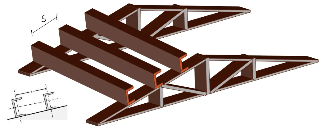
Purlin Load Components
For a roof slope angle $\theta$, resolve the gravity load into components normal and parallel to the roof plane.
$$ w_x=w\cos\theta, \qquad w_y=w\sin\theta $$
$$ M_x=\frac{w_xL^2}{8} \quad \text{for a simple-span purlin} $$
Weak-Axis Bending Strength
506.6 I-Shaped Members and Channels Bent about their Minor Axis
The nominal flexural strength, $M_n$, is the lower value obtained according to the limit states of yielding (plastic moment) and flange local buckling.
506.6.1 Yielding
$$ M_n = M_p = F_y Z_y \leq 1.6 F_y S_y $$
506.6.2 Flange Local Buckling
1. For sections with compact flanges, the limit state of yielding shall apply.
2. For sections with non-compact flanges:
$$ M_n = \left[ M_p - (M_p - 0.7 F_y S_y) \left( \frac{\lambda - \lambda_{pf}}{\lambda_{rf} - \lambda_{pf}} \right) \right] $$
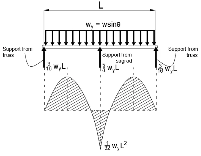
Moment Diagram for Purlins with Sag Rod at the Midspan
$$ M_y=\frac{w_yL^2}{32} \quad \text{for one sag rod at midspan} $$
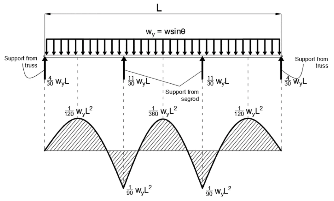
Moment Diagram for Purlins with Sag Rod at Third Points
$$ M_y=\frac{w_yL^2}{72} \quad \text{for sag rods at third points} $$