CE Board Exam Randomizer

⬅ Back to Subject Topics

Welded Connections

Welded connections are widely used in steel structures to transfer loads between members. They provide rigidity, continuity, and strength by joining structural components through welds. The strength of a welded connection depends on the electrode type, the configuration of the welds, and the stresses produced by direct loads and moments. The polar moment of inertia of the weld group is an important parameter in determining the distribution of stresses within the welds.

Electrode used:

Polar Moment of Inertia

$$ J = \sum (I_x + I_y) $$

Simplified Form:

$$ J = \sum L \left(\frac{L^2}{12} + \bar{x}^2 + \bar{y}^2 \right) $$

Where:

Load Effects on Welds

Due to direct load:

$$ P_D = \frac{P}{L} $$

Due to moment/torsion:

$$ R_{Tx} = \frac{T \cdot \bar{y}}{J}, \qquad R_{Ty} = \frac{T \cdot \bar{x}}{J} $$
$$ T=F_xe_y+F_ye_x $$ $$ P=\sqrt{(P_{Dx}+R_{Tx})^2+(P_{Dy}+R_{Ty})^2} $$

For unsymmetrical weld groups, locate the weld centroid by treating weld lengths as line areas.

$$ \bar{x}=\frac{\sum L_i x_i}{\sum L_i}, \qquad \bar{y}=\frac{\sum L_i y_i}{\sum L_i} $$

Minimum Size of Fillet Welds

Material Thickness of Thicker Part Joined (mm) Minimum Size of Fillet Weld (mm)
To 6 mm 3 mm
Over 6 to 12 mm 5 mm
Over 12 to 20 mm 6 mm
Over 20 mm 8 mm

Maximum Size of Fillet Welds

Material Thickness Maximum Size of Fillet Weld
< 6 mm Not greater than thickness of material
> 6 mm Not greater than thickness of material minus 1.6 mm

Welded Connections (Axially Loaded)

I. Longitudinal Fillet Welds Only

Concept

A. Tensile Capacity of Base Metal Connection

1) Tension Yielding on Gross Area

$$Pn = Fy (Ag)$$ $$Ag = w(t)$$

Pa = 0.60 Pn (For ASD)
Pu = 0.90 Pn (For LRFD)

2) Tension Rupture on Net Section of the Base Metal

Pn = Fu (Ae)

Ae = UAn,   An = Ag (since there are no bolt holes for welds)
Pa = 0.50 Pn (For ASD)
Pu = 0.75 Pn (For LRFD)

Where:
Fy = yield stress of the base metal
Fu = specified ultimate stress of the base metal
t = thickness of the base metal
U = shear lag factor

Note: Use the smaller value of Pn for tensile capacity of the base metal.

Shear Strength of the Base Metal

Concept

1) Based on Gross Area of Shear Surface

$$Pn = 0.60 Fy Ag$$

Ag = t(Lt)
t = smaller thickness of t1 and t2
Lt = total length of the weld

2) Based on Shear Rupture Strength

$$Pn = 0.60 F_u A_{nv}$$

Anv = t(Lt)
t = smaller thickness of t1 and t2
Lt = total length of the weld

Pa = 0.50 Pn (For ASD)
Pu = 0.75 Pn (For LRFD)

3) Weld Shear Strength

$$Pn = F_{nw} (A_{we})$$ $$ A_{we}=0.707wL_t, \qquad F_{nw}=0.60F_{EXX} $$

Where:
Awe = 0.707 (t)(Lt)
t = thickness of the weld in mm
Fnw = 0.60 Fu (tension strength of the weld)
Lt = total length of the longitudinal welds

Load Resistance Factored Design (LRFD)

$$\phi Pn = \phi F_{nw} (A_{we})$$

Where: Φ Pn = design shear strength of weld, Φ=0.75

Allowable Stress Design (ASD)

$$Pa = Pn / Ω = F_{nw} (A_{we}) / Ω$$

Where: Pa = design shear strength of weld, Ω = 2


II. Longitudinal & Transverse Fillet Welds

Concept
$$P_{n1} = Pn_{wl} + Pn_{wt} $$
$$P_{n2} = 0.85 Pn_{wl} + 1.5 Pn_{wt}$$

Where:
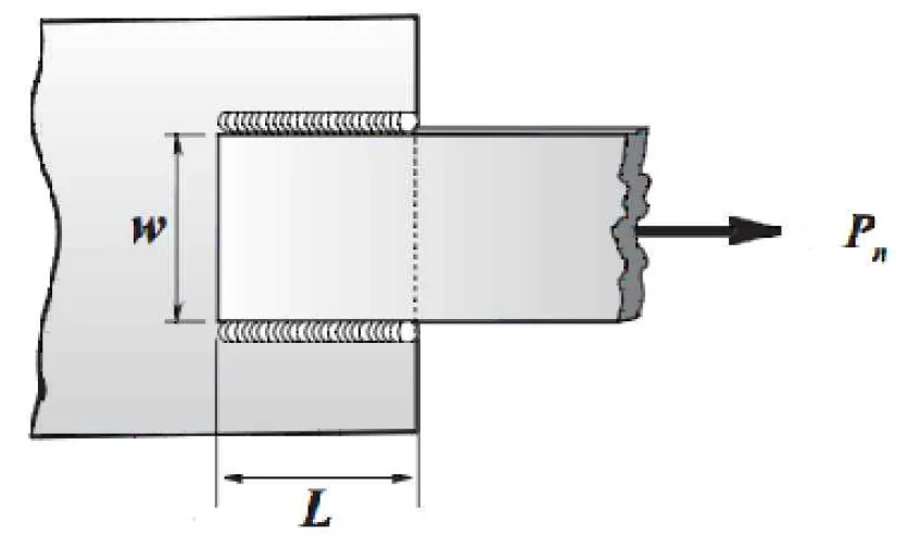
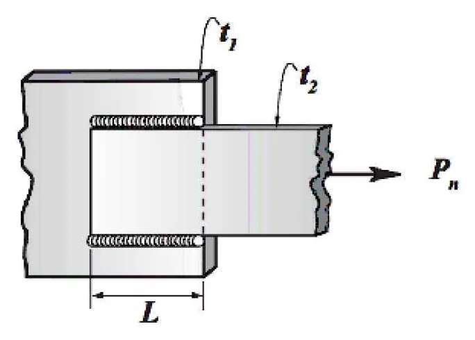
Pnwl = total nominal strength of the longitudinal fillet welds
Pnwt = total nominal strength of the transversely loaded fillet welds
Pnwl = Fnw (Awe)

Note: Use the larger value between Pn1 and Pn2 as the design Pn.

Concept Concept Concept Concept Concept Concept

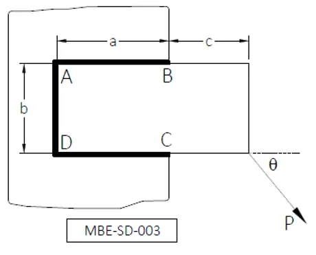
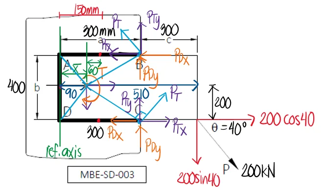
Problem: Welded Bracket Under Inclined Eccentric Load

Given the following data for the welded bracket shown below: a = 300 mm, b = 400 mm, c = 300 mm, and allowable shear stress of weld metal is 145 MPa. If P = 200 kN and θ = 40°, answer the following:

Welded Connection | Principles of Steel Design - Problem 1: Welded Bracket Under Inclined Eccentric Load - Diagram
  1. What is the unit polar moment of inertia of the weld group in mm3?
    1. 49.30 × 10⁶
    2. 24.90 × 10⁶
    3. 39.20 × 10⁶
    4. 56.60 × 10⁶
  2. Which of the following most nearly gives the reaction at C in N/mm?
    1. 336.40
    2. 316.50
    3. 487.60
    4. 457.50
  3. Which of the following most nearly gives the reaction at B in N/mm?
    1. 336.40
    2. 316.50
    3. 487.60
    4. 457.50
Welded Connection | Principles of Steel Design - Problem 1: Welded Bracket Under Inclined Eccentric Load - Diagram

Find the centroid of the weld group from the left vertical weld.

$$ L_Tx=400(0)+2(300)(150) $$ $$ x=90\text{ mm} $$

Compute the torsional moment from the resolved components of P.

$$ T=200\sin(40^\circ)(510)-200\cos(40^\circ)(200) $$ $$ T=34922.558\text{ kN-mm} $$

Compute the unit polar moment of inertia of the weld group.

$$ J=\sum L\left(\frac{L^2}{12}+x^2+y^2\right) $$ $$ J=2(300)\left(\frac{300^2}{12}+60^2+200^2\right)+400\left(\frac{400^2}{12}+90^2\right) $$ $$ J=39233333.333\text{ mm}^3\approx 39.20\times10^6\text{ mm}^3 $$

For the torsional weld reactions, check the extreme weld points because they are farthest from the weld-group centroid and therefore usually develop the largest torsional components. The torsional force at a point on the weld group acts perpendicular to the radial line drawn from the centroid to that point, with direction chosen to resist the rotation caused by the eccentric load. For a point with vertical offset y and horizontal offset x from the centroid, PTx is associated with the y-distance, while PTy is associated with the x-distance.

Resolve the direct and torsional weld reactions.

$$ P_{Dx}=\frac{200\cos(40^\circ)(1000)}{L_T}=153.209\text{ N/mm} $$ $$ P_{Dy}=\frac{200\sin(40^\circ)(1000)}{L_T}=128.558\text{ N/mm} $$ $$ P_{Tx}=\frac{T(200)(1000)}{J}=178.025\text{ N/mm} $$ $$ P_{Ty}=\frac{T(210)(1000)}{J}=186.926\text{ N/mm} $$

Resultant weld reactions at C and B:

$$ R_C=\sqrt{(-P_{Dx}+P_{Tx})^2+(P_{Dy}+P_{Ty})^2}=316.458\text{ N/mm} $$ $$ R_B=\sqrt{(P_{Dx}-P_{Tx})^2+(P_{Dy}+P_{Ty})^2}=457.434\text{ N/mm} $$

Final answers: a. C. 39.20 × 10⁶; b. B. 316.50; c. D. 457.50

Welded Connection | Principles of Steel Design - Problem 1: Welded Bracket Under Eccentric Load - Solution
Scroll to zoom

Exam Generator Problems

Additional board-style practice items for this topic.

Question Bank: q49

PSAD - Steel Design / Welded Connections / Engr. Janclyde Espinosa (Clidez)

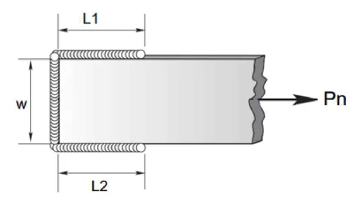
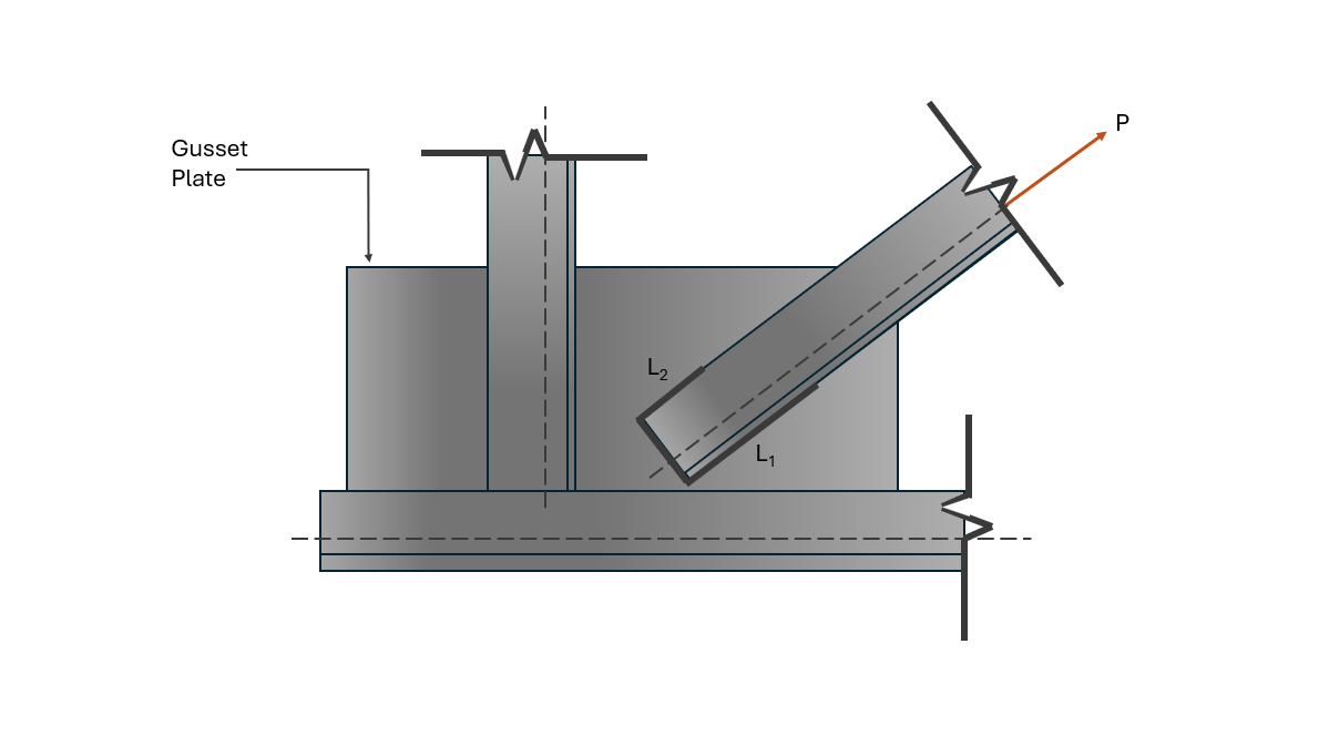
The diagonal member, a single angle 76mmx76mmx6mm with an area of 929mm2 is welded to an 8-mm thick gusset plate. The weld electrode used is E60. Assume load P is acting on the centroid of the weld group.
Given weld lengths:
L1=125mm
L2=65mm
Steel strength and stress are as follows:
Fy=248MPa
Fu=400MPa
Gross area yielding, Ft=0.6Fy
Net area rupture, Ft=0.5Fu
On effective area of weld in shear, Fv=0.3Fuw

q49

Based on the effective net area of the diagonal, calculate the allowable tensile load in kN. Use strength reduction coefficient of 85%.

  1. 157.93
  2. 185.8
  3. 138.24
  4. 162.64

Based on the strength of the fillet welds, calculate the allowable tensile load in kN. Take the weld thickness as 5mm.

  1. 116.79
  2. 185.8
  3. 304
  4. 296.83

Given the following properties of L76x76x6:
DIstance from the outermost part of the angle leg to the centroid of the angle bar, x=22mm
Shear lag factor, U=1-x/ℓ

  1. 0.768
  2. 0.884
  3. 0.93
  4. 0.86

Solution pending in psadquestions/q49.json.

Question Bank: q50

PSAD - Steel Design / Welded Connections / Engr. Janclyde Espinosa (Clidez)

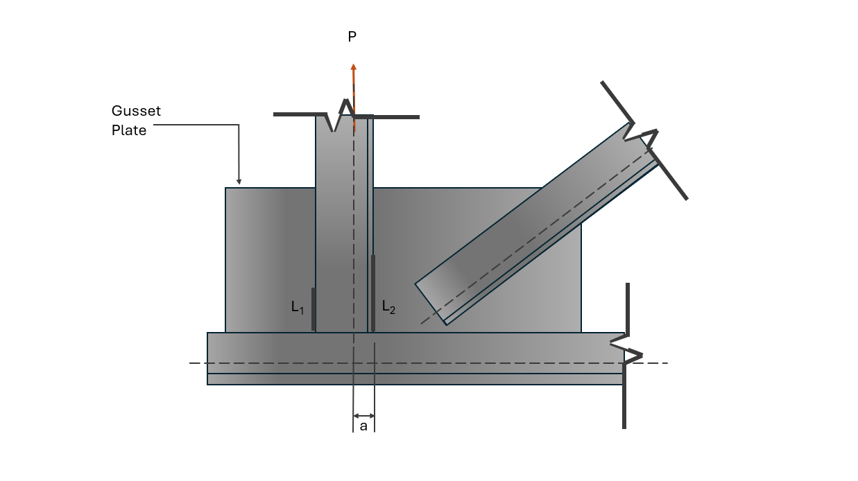
The vertical member consisting of two unequal leg angle with long legs back-to-back are welded to the 8-mm thick gusset plate. Given the following:
a=25mm
Weld thickness=5mm
Angle size=75mmx50mmx6mm thick
Steel yield stress, Fy=248MPa
Area of two angles=1535mm2
Allowable weld shear stress, Fv=124MPa

q50

What is the tensile capacity, P (kN), of the vertical member?

  1. 228.411
  2. 218.423
  3. 240.624
  4. 238.142

Due to a force P=60.5kN, what is the length of weld L2 so that each fillet weld is equally stressed in shear? Neglect end returns.

  1. 46
  2. 52
  3. 50
  4. 48

Solution pending in psadquestions/q50.json.