Bolted Connections
In the previous sections, we have already discussed the failure modes based on the tension of the plate (gross area, net area, and staggered connections), as well as block shear. Here, we will discuss the bearing of the plate, which is the shear tear out at the end of a connected element, and the effects of torsion on bolts due to eccentric loadings.
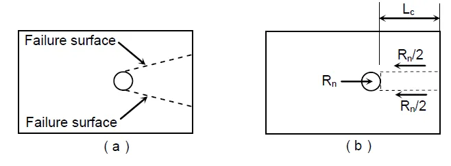
From the idealized failure surface, the total nominal strength is:
Where:
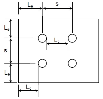
- $L_c$ = clear distance, measured in the direction parallel to the applied load, from the edge of the bolt hole to the edge of the adjacent hole or to the material edge
- $t$ = thickness of the connected part
- $F_u$ = ultimate tensile stress of the connected part (not the bolt)
- $d$ = bolt diameter
- $2.4dtF_u$ = upper limit of $R_n$
For LRFD:
For ASD:
Spacing and Edge - Distance Requirements
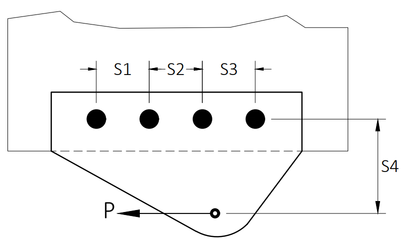
Minimum spacing, S, and edge distance, Le, in any direction, both in the line of force and transverse to the line of force.
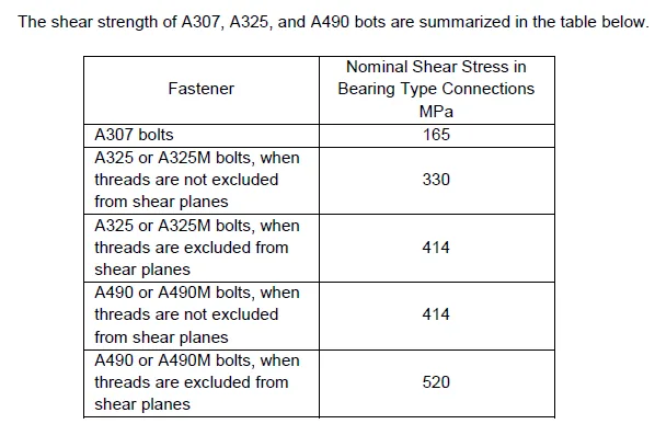
Bolt shear strength
For LRFD:
For ASD:
Other bearing-strength cases from NSCP/AISC notes
Combined bolt shear and tension
Eccentric Bolted Connections (Elastic Analysis)
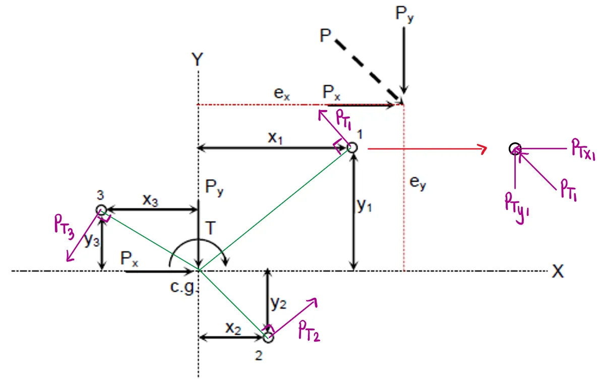
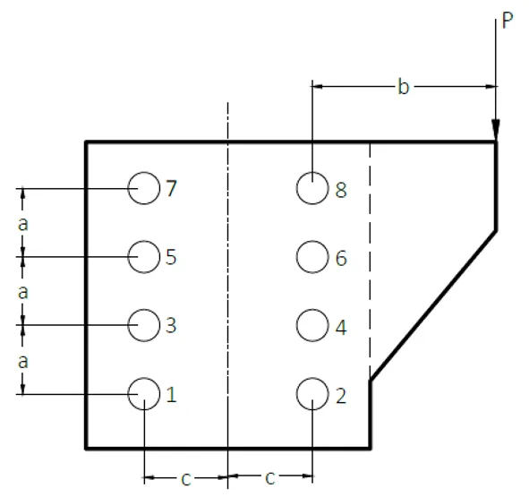
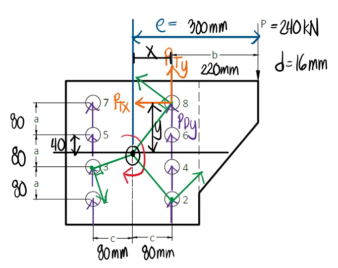
Consider the bolted connection acted by a force P as shown.
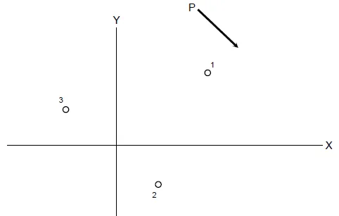
1. Resolve P into components Px and Pyand construct the equivalent loading
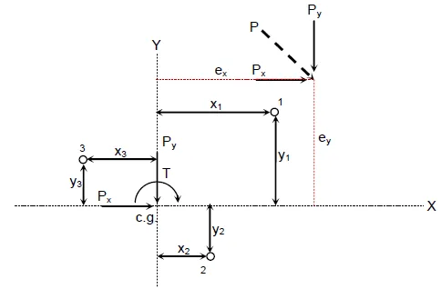
2. Locate the center of gravity of the bolt group. For symmetrical arrangements of bolts, the center of gravity is located at the geometric center. For non=symmetrical arrangements, it can be located by using Varignon's Theorem
3. The equivalent effect is that the system of bolts is acted by direct shears Px and Py and a torsional moment T at the center of gravity.
Equivalent Loading
Bolt Group: Direct Shear + Torsion (Procedure)
-
For direct shear loads, distribute equally among the bolts:
$$ P_{Dx} = \frac{P_x}{n}, \qquad P_{Dy} = \frac{P_y}{n} $$where $n$ = number of bolts.
-
Compute the torsional moment about the bolt group centroid:
$$ T = P_x e_y + P_y e_x $$
-
The most stressed bolt is where the forces due to direct shear and torsion are of similar directions. Forces due to direct shear have the same directions as the components of the applied force. For the forces due to torsion, draw lines (indicated as green lines) from the c.g. going to the center of each bolt. Next, draw forces perpendicular to such line (indicated as purple lines) that cause a rotation opposite to the torsional moment.
Since the torsional moment is clockwise, the forces, PT1, PT2, and PT3 must cause a counterclockwise rotation. -
Consider bolt 1. The torsion-induced load on bolt 1 is $P_T$, resolved into components:
$$ P_{Tx1} = \frac{T\,y_1}{\sum (x^2 + y^2)}, \qquad P_{Ty1} = \frac{T\,x_1}{\sum (x^2 + y^2)} $$Define the polar moment of the bolt group:$$ J = \sum (x^2 + y^2) $$
-
Select the bolt with the maximum combined shear (direct + torsion). The total resultant on that bolt is:
$$ P = \sqrt{\left(P_{Tx} + P_{Dx}\right)^2 + \left(P_{Ty} + P_{Dy}\right)^2} $$