CECC-483 Reference Formula Sheet — One-Way Slabs & NSCP Coefficients
Complete one-way slab design workflow plus the ACI/NSCP moment-shear coefficients used for continuous beams and one-way slabs (CECC-483 review notes).
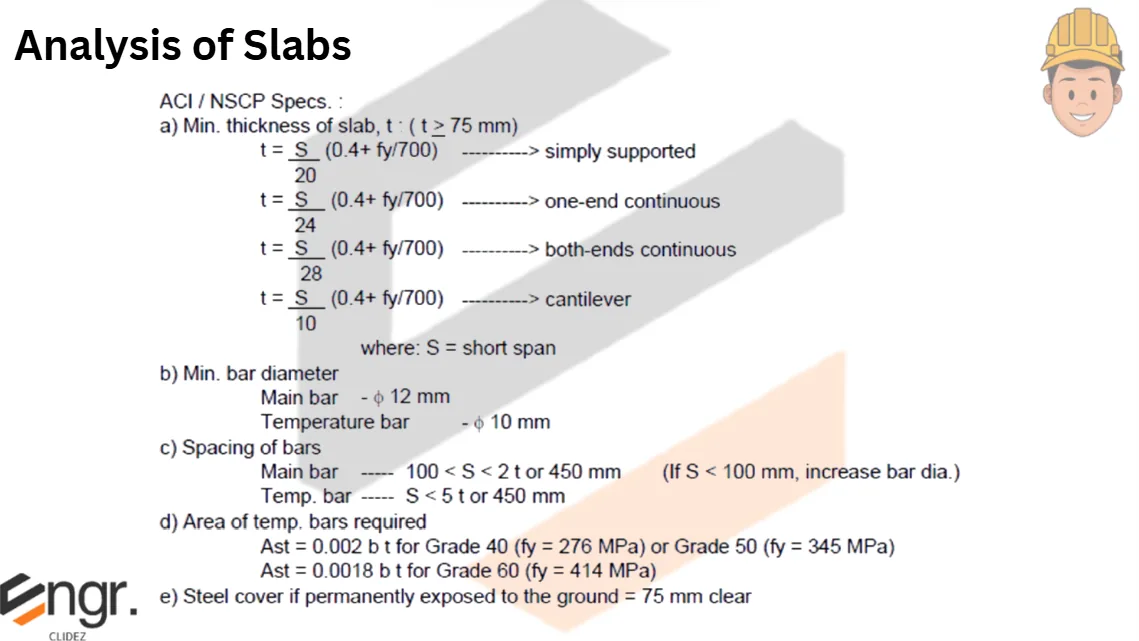
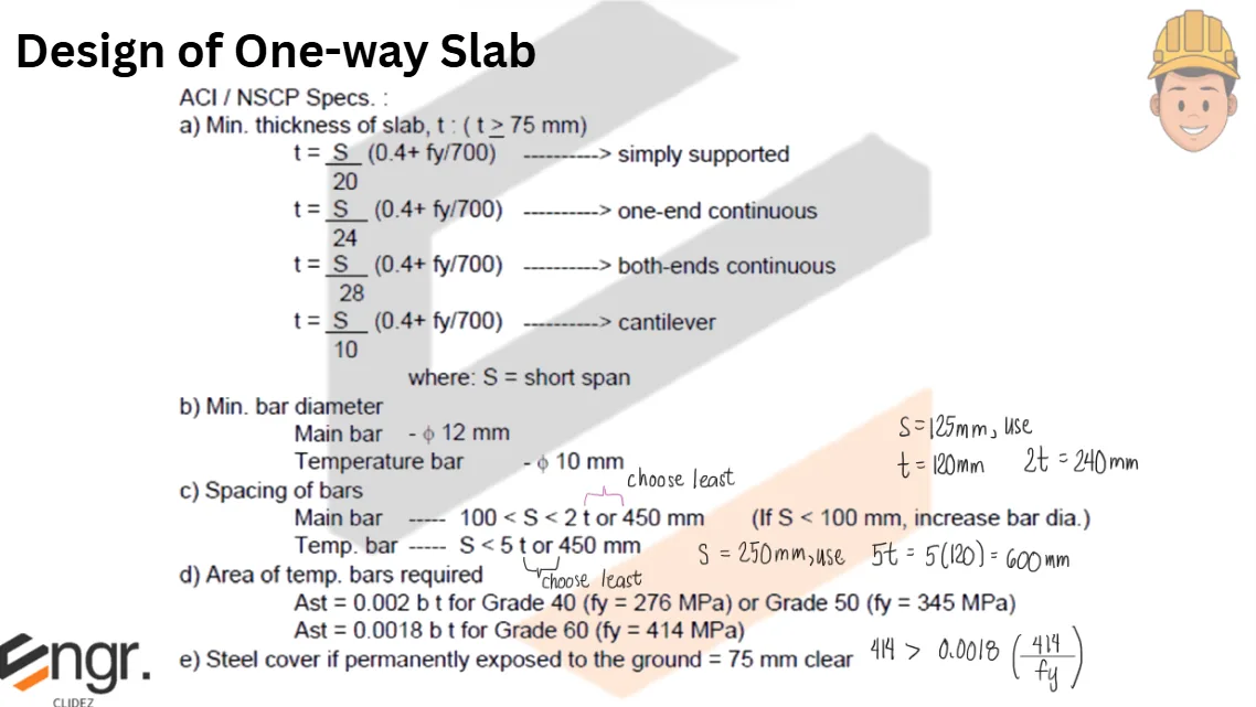
NSCP Table 409-1 — Minimum thickness h (deflection not computed):
Member
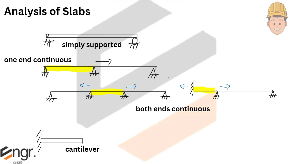
Simply supported
One-end continuous
Both-end continuous
Cantilever
Solid one-way slabs
L/20
L/24
L/28
L/10
Beams or ribbed one-way slabs
L/16
L/18.5
L/21
L/8
For lightweight concrete with $w_c$ between 1500 and 2000 kg/m³: multiply by $(1.65-0.0003w_c) \ge 1.09$. For $f_y \ne 420$ MPa: multiply by $(0.4 + f_y/700)$.
Steps in designing a one-way slab:
Assume slab thickness $h$ from Table 409-1.
Consider a 1-m strip ($b = 1000$ mm).
Compute the factored load and ultimate moment.
Compute the effective depth: $d = h - \text{clear cover} - \tfrac{1}{2}d_b$.
Compute the coefficient of resistance $R_n = M_u/(\phi b d^2)$ assuming $\phi = 0.90$.
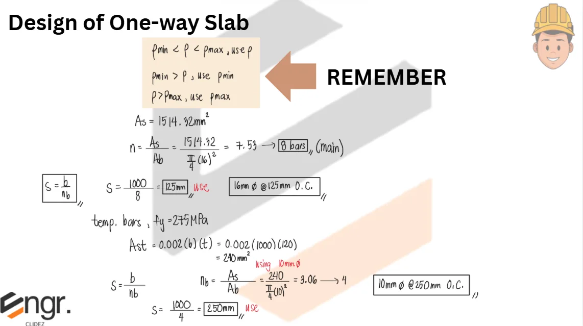
Spacing of temperature bars: $S = (A_b/A_{st})\times 1000$.
Bar diameter spacing limits:
Main bars: $100 < S < 3t$ or 450 mm. (If $S < 100$ mm, increase the bar diameter.)
Temperature bars: $S \le 5t$ or 450 mm, whichever is smaller.
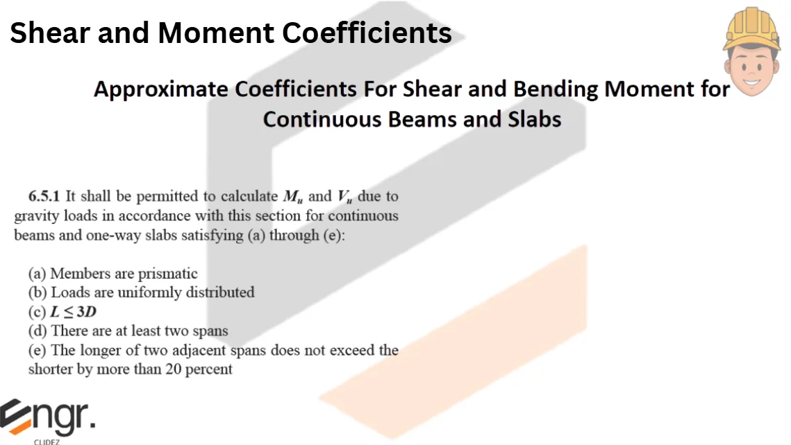
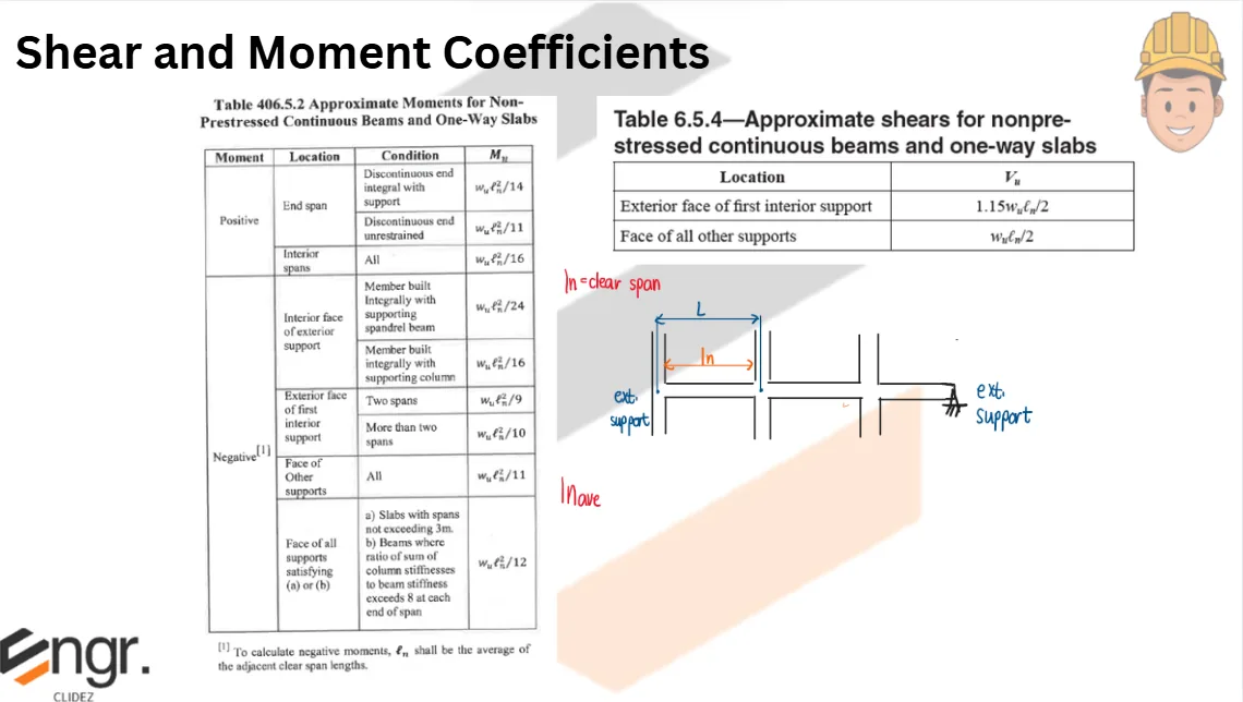
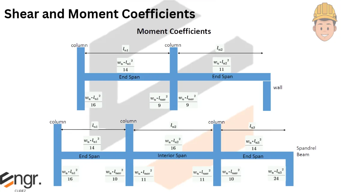
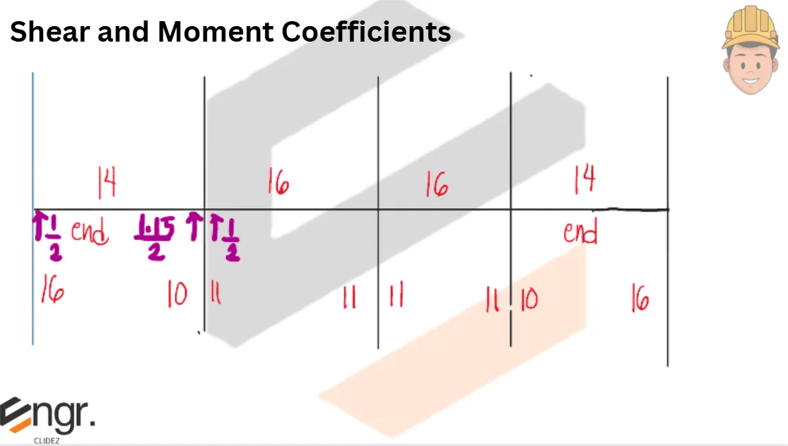
ACI/NSCP simplified moment coefficients for non-prestressed continuous beams and one-way slabs (applies if members are prismatic, loads uniformly distributed, $L \le 3D$, at least two spans, and the longer of two adjacent spans does not exceed the shorter by more than 20%):
Moment
Location
Condition
Mu
Positive
End span
Discontinuous end integral with support
$w_u L_n^2 / 14$
Discontinuous end unrestrained
$w_u L_n^2 / 11$
Interior span
All
$w_u L_n^2 / 16$
Negative
Interior face of exterior support
Member built integrally with supporting beam
$w_u L_n^2 / 24$
Member built integrally with supporting column
$w_u L_n^2 / 16$
Exterior face of first interior support
Two spans
$w_u L_n^2 / 9$
More than two spans
$w_u L_n^2 / 10$
Negative
Face of other supports
All
$w_u L_n^2 / 11$
Negative
Face of all supports
Slabs with spans ≤ 3 m; or beams with ratio of column-stiffness sum to beam-stiffness exceeding 8 at each end
$w_u L_n^2 / 12$
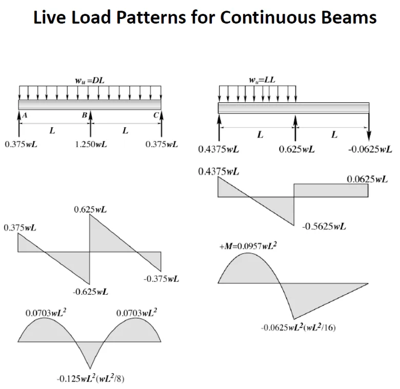
Approximate shears for non-prestressed continuous beams and one-way slabs:
Location
Vu
Exterior face of first interior support
$1.15\,w_u L_n / 2$
Face of all other supports
$w_u L_n / 2$
$w$ = total unit load per unit length; $L_n$ = clear span (positive moment & shear); average of adjacent spans for negative moments.
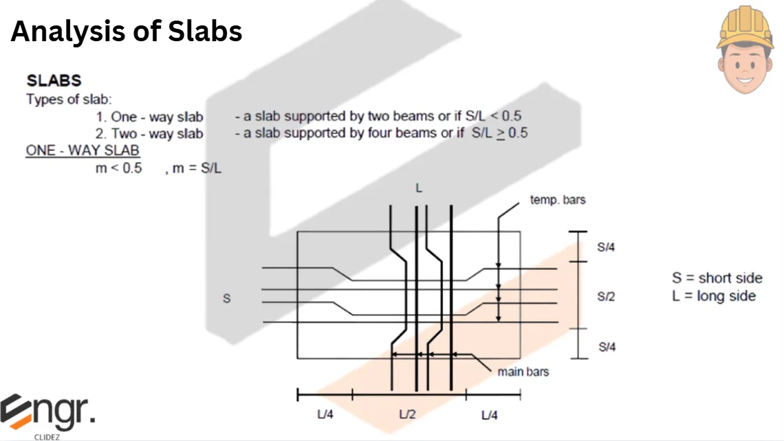
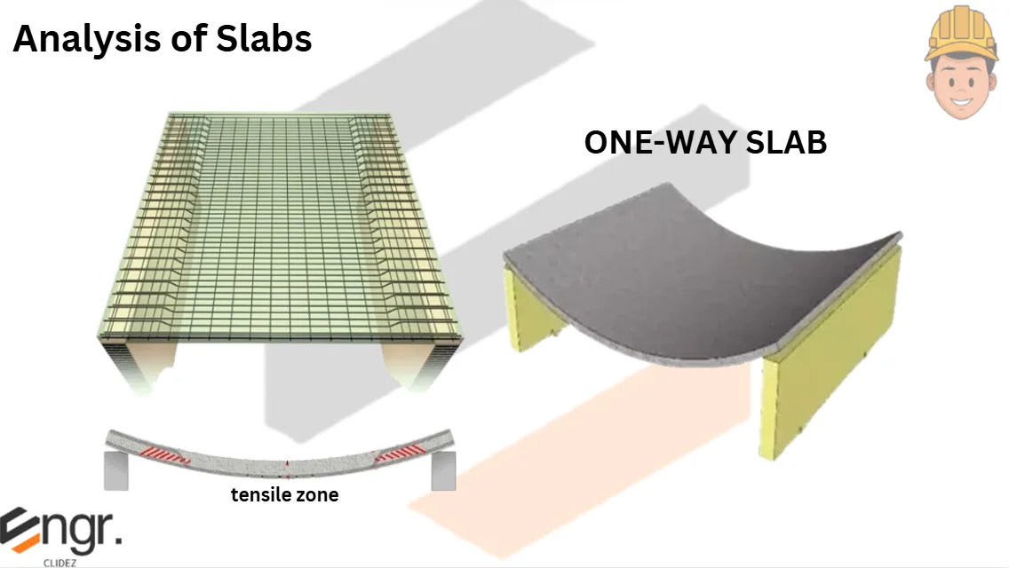
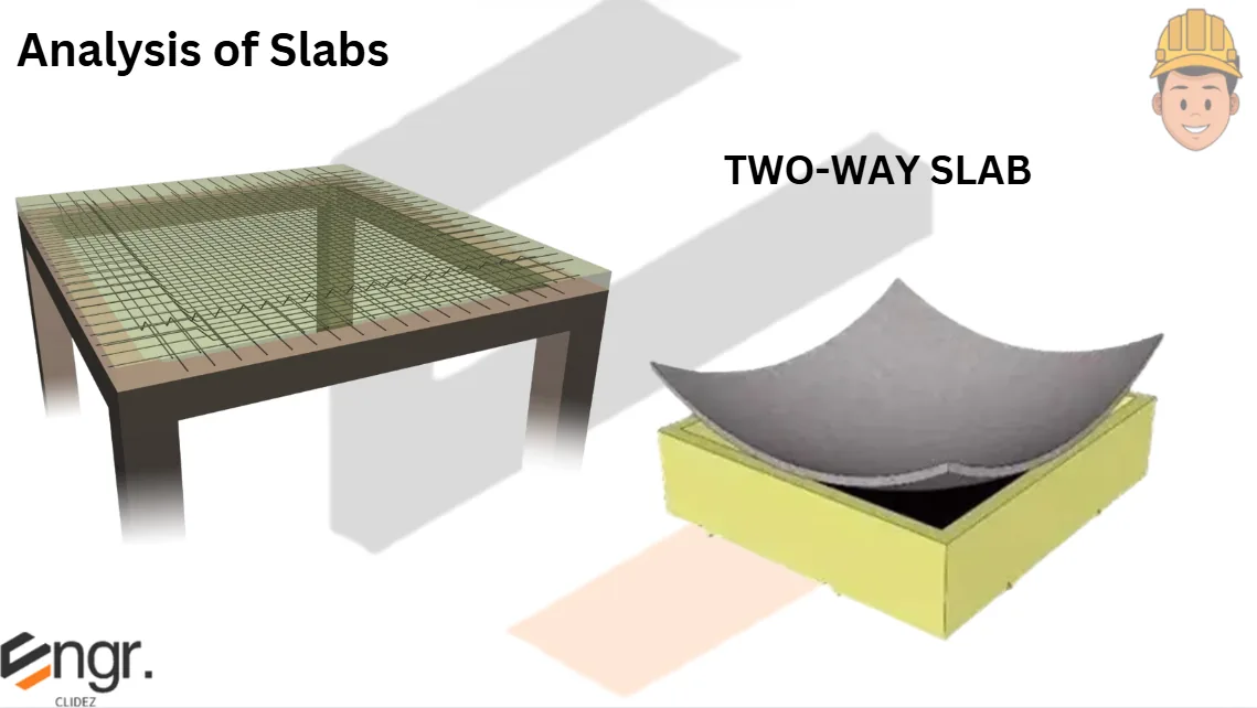
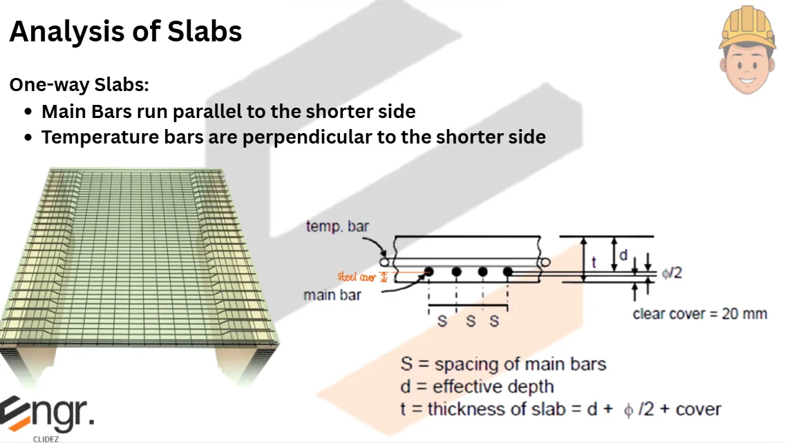
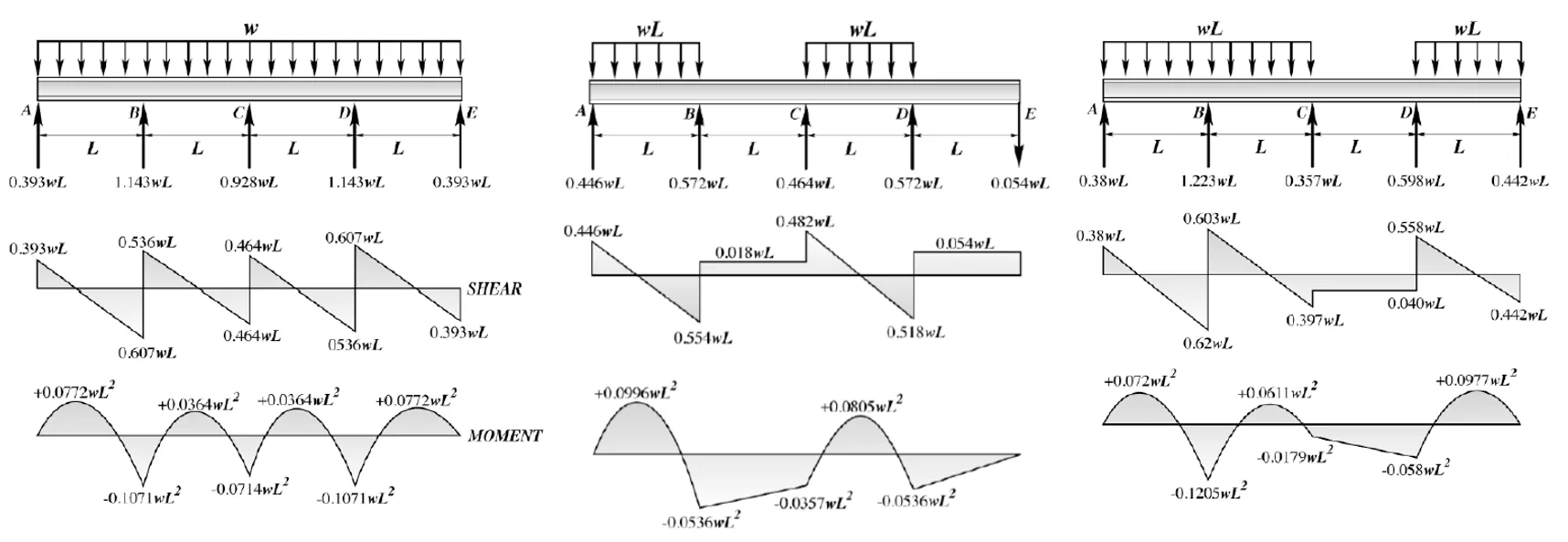
Analysis of Slabs
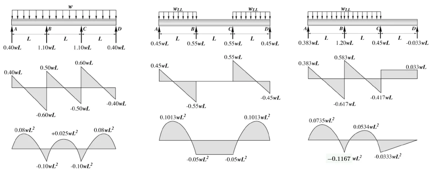
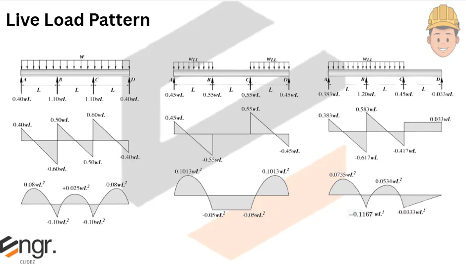
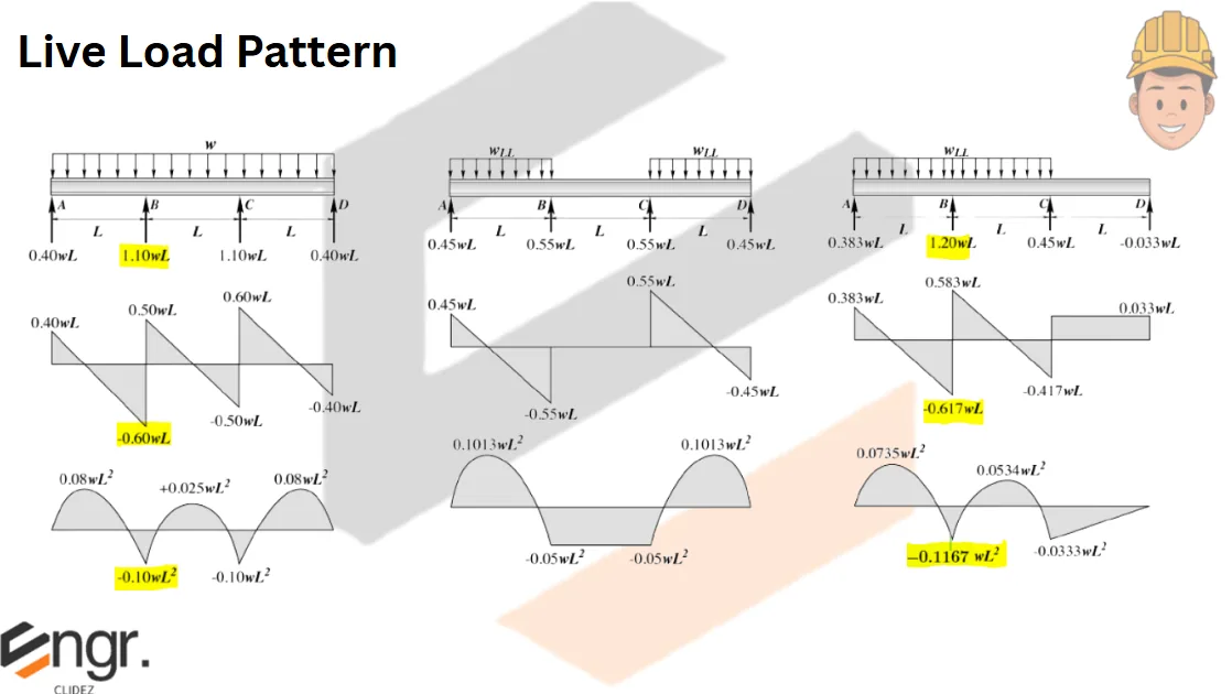
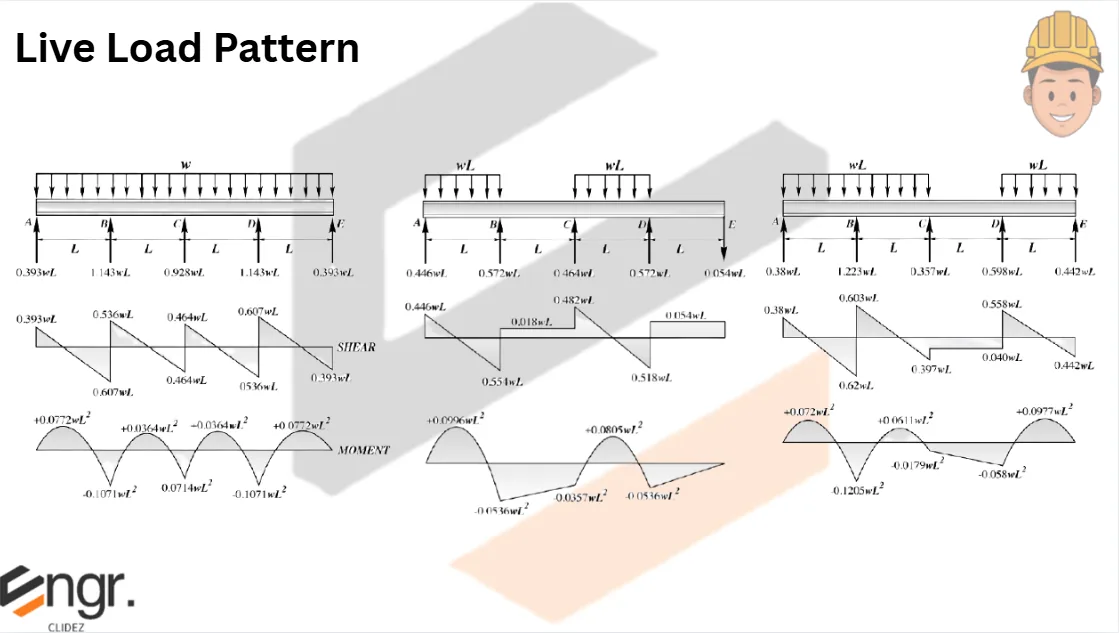
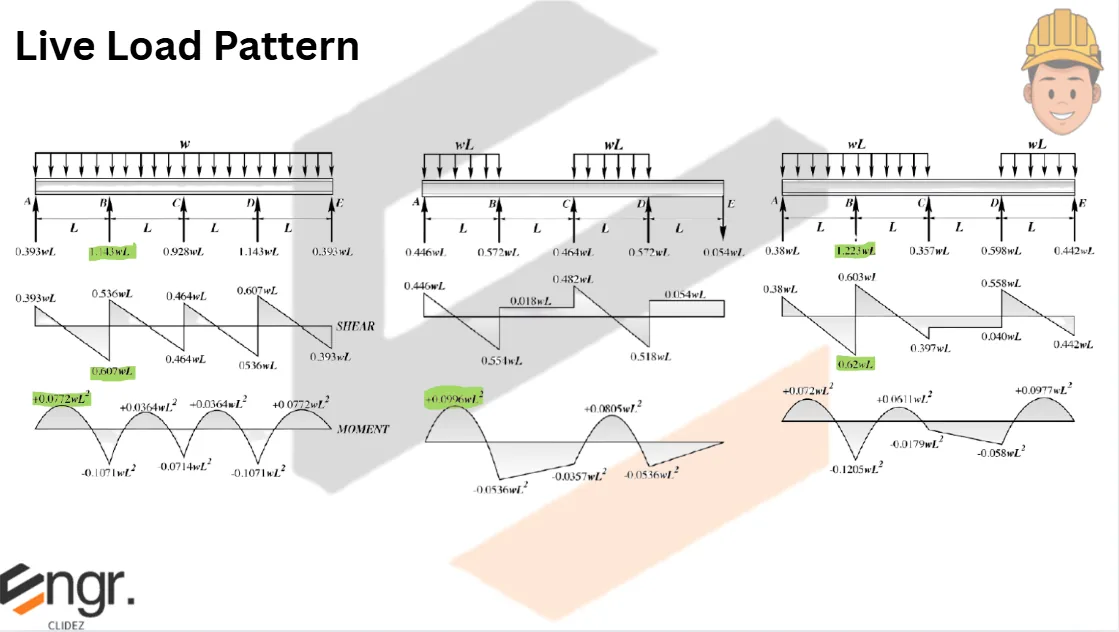
Live Load Patterns
Shear and Moment Coefficients
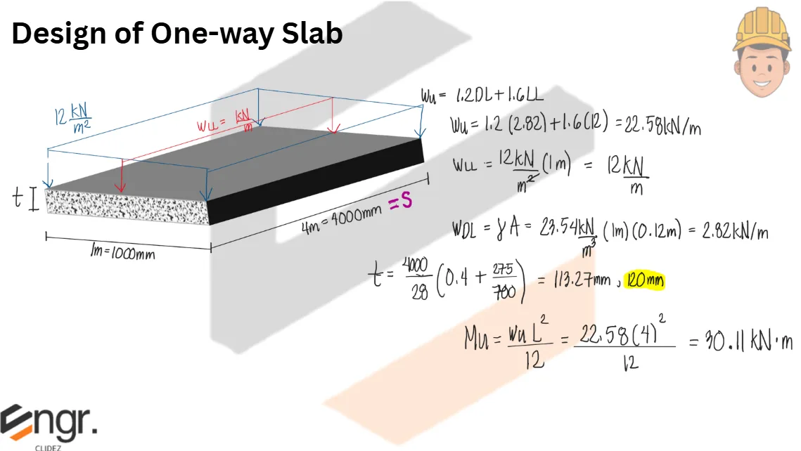
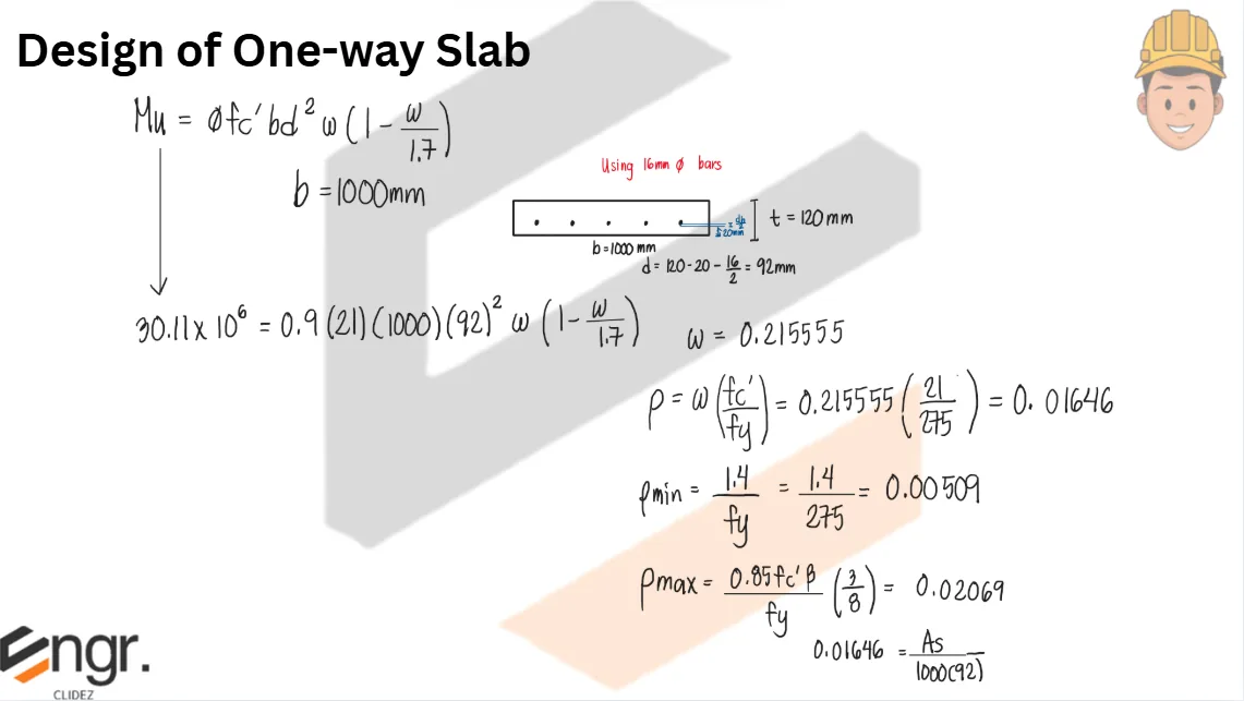
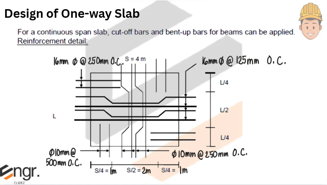
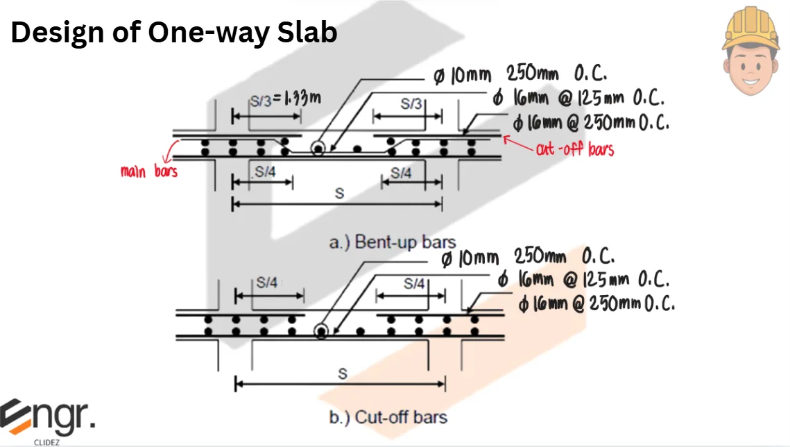
Problem:
Design a one-way slab to carry a service live load of 12kN/m2 on a continuous span of 4m. Use f'c = 21MPa, fy = 275MPa, unit weight of concrete = 23.54kN/m3. Mu=wuL2/12 at supports and midspan.
See images:
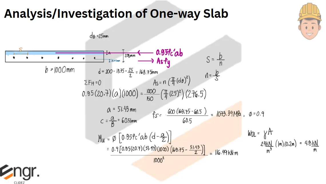
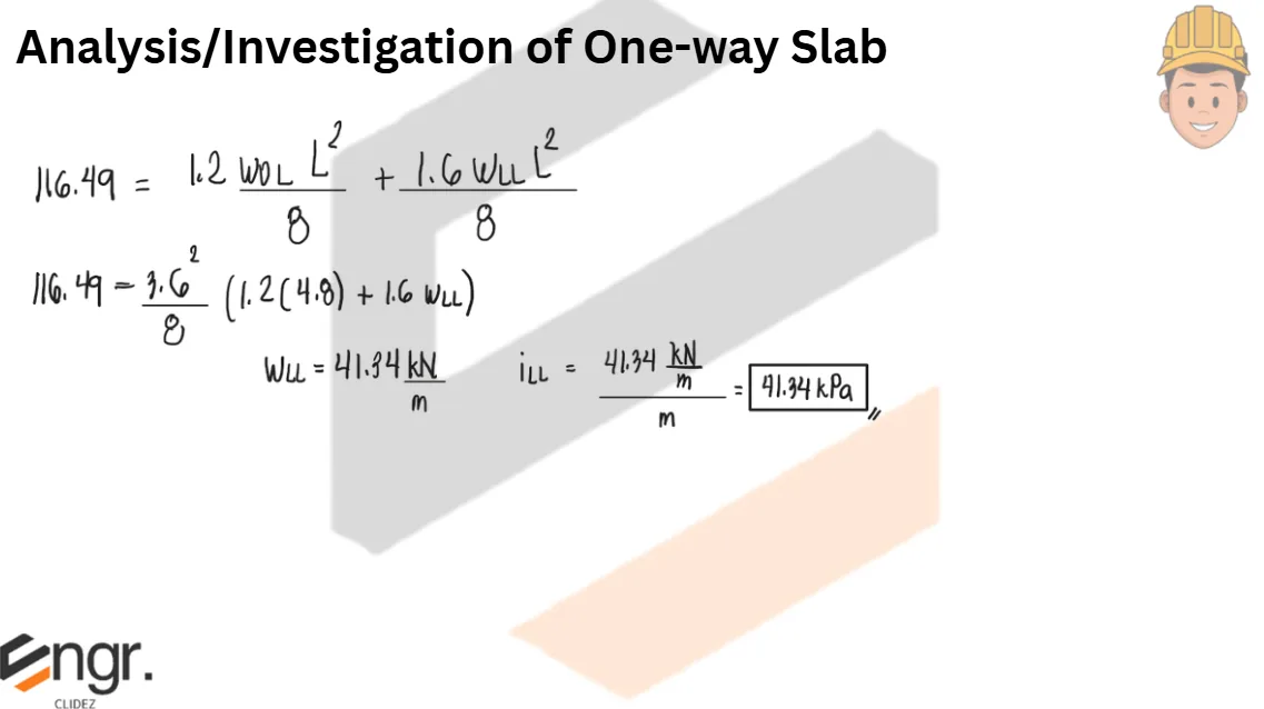
Problem:
The one-way slab has a thickness of 200 mm. It is reinforced with 25mmΦ bars spaced at 150mm on center. Clear covering is 18.75, fc'=20.7MPa, fy=276.5MPa, wt. of concrete = 24kN/m3. Span of slab is 3.6m center to center of support. Compute the service live load in kPa that the slab could carry assuming the only dead load is the weight of the slab. (Use NSCP 2010)
A. 47.48kPa B. 34.78kPa C. 40.58kPa D. 41.34kPa
See images:
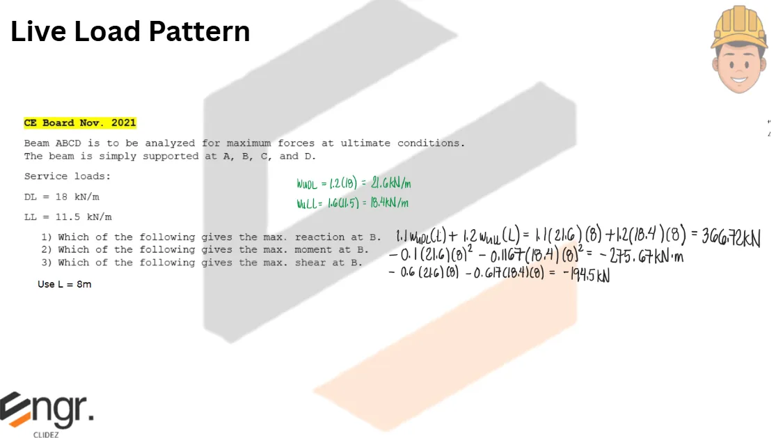
Problem:
CE Board November 2021
Beam ABCD is to be analyzed for maximum forces at ultimate conditions. The beam is simply supported at A, B, C, and D. Service Loads: DL=18kN/m LL=11.5kN/m 1. Which of the following gives the maximum reaction at B? 2. Which of the following gives the maximum moment at B? 3. Which of the following gives the maximum shear at B?
See images:
Problem:
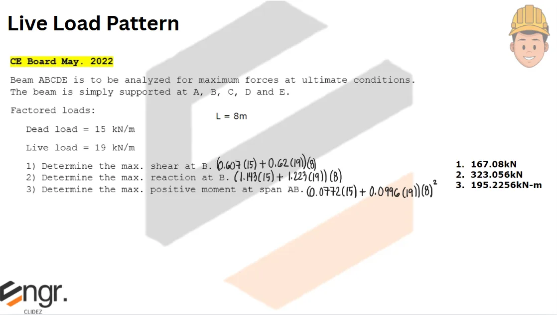
CE Board May 2022
Beam ABCDE is to be analyzed for maximum forces at ultimate conditions. The beam is simply supported at A, B, C, D, and E. Factored Loads: DL=15kN/m LL=19kN/m 1. Determine the maximum shear at B. 2. Determine the maximum reaction at B. 3. Determine the maximum positive moment at span AB.
See images:
Problem:
CE Board May 2022
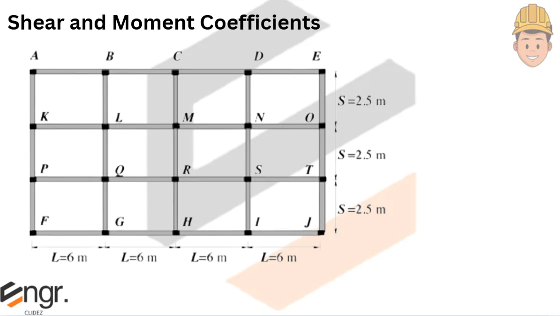
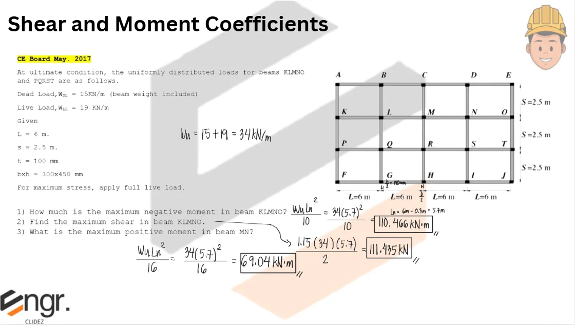
At ultimate condition, the uniformly distributed loads for beams KLMNO and PQRST are as follows: Dead Load, wDL=15kN/m (beam weight included) Live Load, wLL=19kN/m L=6m s=2.5m t=100mm bxh=300mm450mm For maximum stress, apply full live load. Note: Use b=300mm as the column dimension parallel to the beam length
1. How much is the maximum negative moment in beam KLMNO? 2. Find the maximum shear in beam KLMNO. 3. What is the maximum positive moment in beam MN?
See images:
Problem:
CE Board May 2022
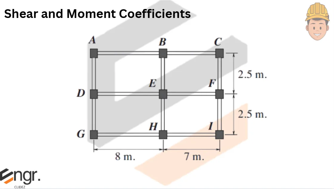
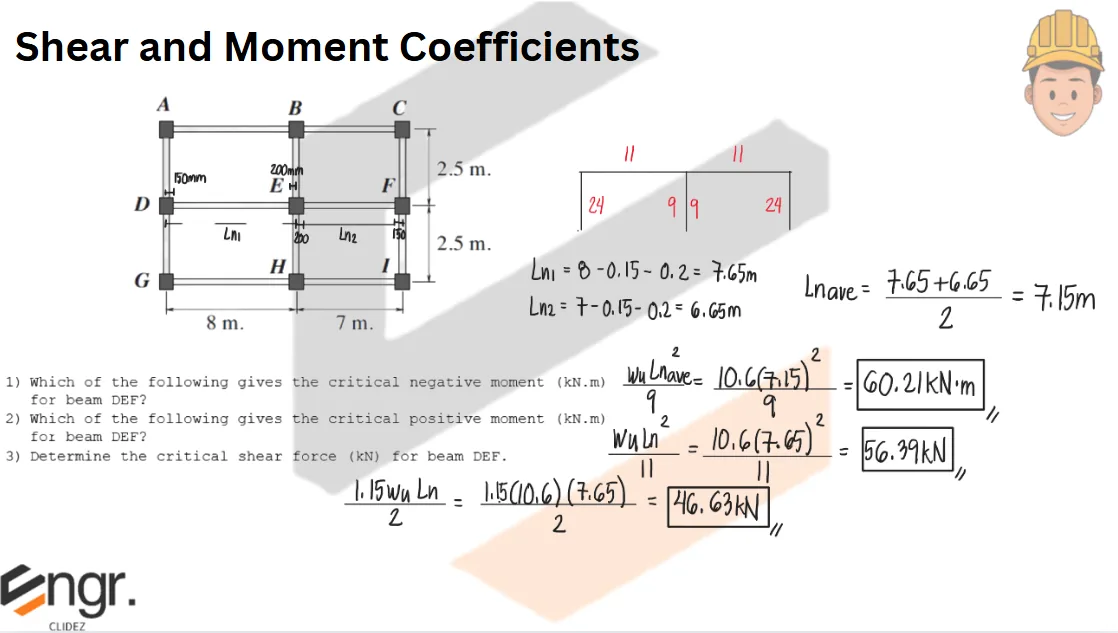
Beam DEF is supported by spandrel beams at the exterior edges and by a column at E. The torsional resistance of beam ADG and CFI are not sufficient to restrain beam DEF at D and F. For all beams, bxh = 300mmx450mm For all column sections = 400mmx400mm Dead Load, wuDL=6kN/m (beam weight included) Live Load, wuLL=4.6kN/m 1. What is the critical negative moment at beam DEF? 2. Determine the critical positive moment at beam DEF. 3. Determine the critical shear force at beam DEF.
See images:
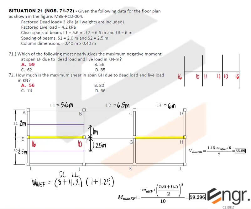
Problem: Floor Slab Moments and Shear
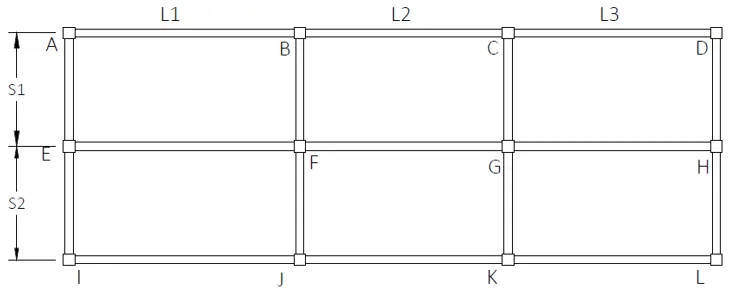
Given the following data for the floor plan shown below:
Factored dead load = 3 kPa (all weights are included)
Factored live load = 4.2 kPa
Clear spans of beam: L1 = 5.6 m, L2 = 6.5 m, and L3 = 6 m
Spacing of beams: S1 = 2.0 m and S2 = 2.5 m
Column dimensions = 0.40 m × 0.40 m
Which of the following most nearly gives the maximum negative moment at span EF due to dead load and live load in kN-m?
59
56
62
85
How much is the maximum shear in span GH due to dead load and live load in kN?
56
80
74
66
See images:
🧭 Jump to:
Scroll to zoom
Exam Generator Problems
Additional board-style practice items for this topic.
Question Bank: q135
PSAD - Reinforced Concrete / Analysis and Design of Slabs / Engr. Janclyde Espinosa (Clidez)
A 150mm thick slab has the following specifications: f'c=27.5MPa Clear concrete cover = 20mm fy = 275MPa for 12mm⌀ and 10mm⌀ bars fy = 413MPa for 16mm⌀ bars
Determine the ultimate flexural strength (in kN-m) of the slab if it is reinforced with 10mm⌀ bars spaced at 125mm center to center.
19
15
17
21
Determine the ultimate flexural strength (in kN-m) of the slab if it is reinforced with 16mm⌀ bars spaced at 200mm center to center.
42.30
32.90
28.40
36.80
If 10mm⌀ bars are replaced with 12mm diameter bars, what is the spacing (in mm) of the 12-mm diameter bars?
Same $\phi M_n$ as Case 1, using 12mm bars at $f_y = 275$ MPa. $d_{12} = 150 - 20 - 6 = 124$ mm Solving iteratively: $A_s \approx 633 \text{ mm}^2$ Area per 12mm bar: $\frac{\pi(12)^2}{4} = 113.1 \text{ mm}^2$ Spacing = $\frac{113.1 \times 1000}{633} \approx 179$ mm → use $\boxed{\approx 175 \text{ mm}}$