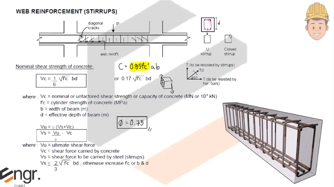
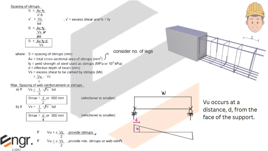
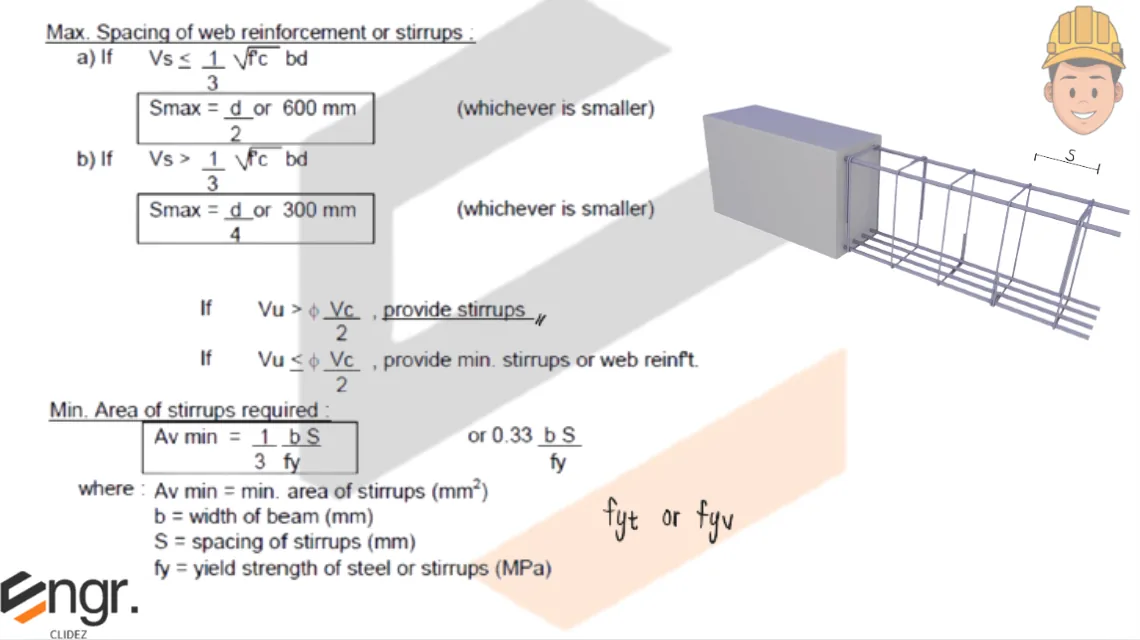
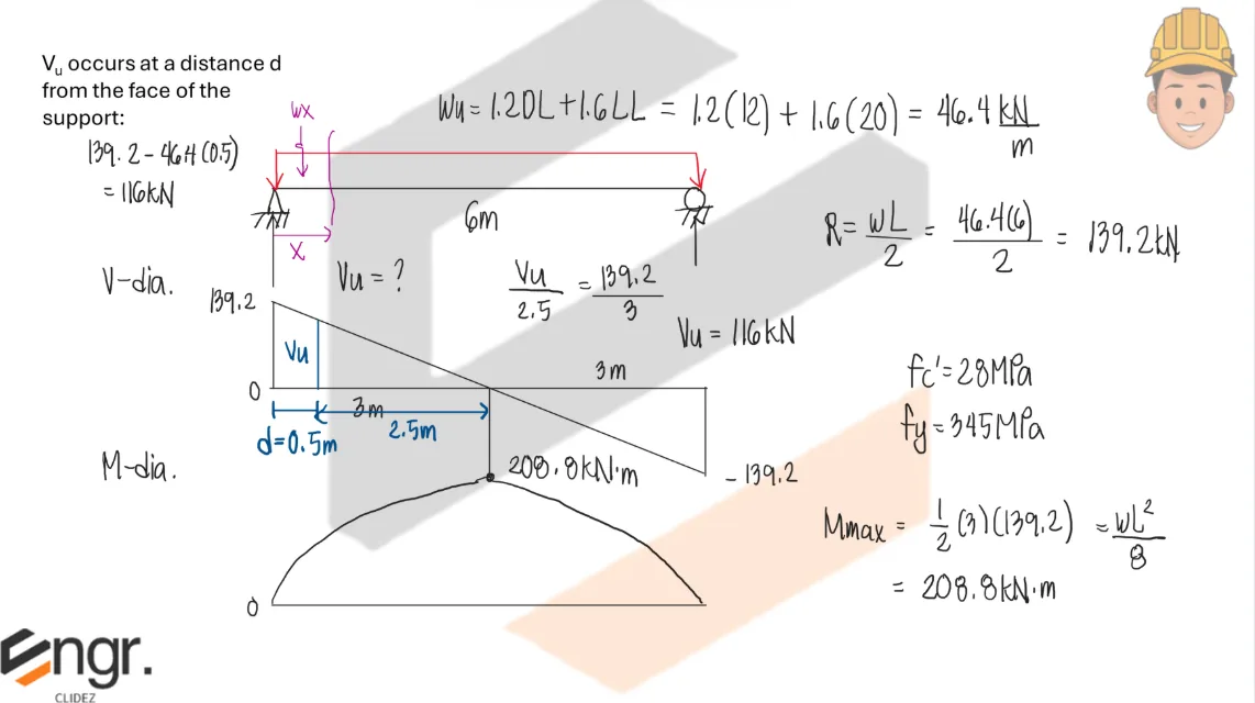
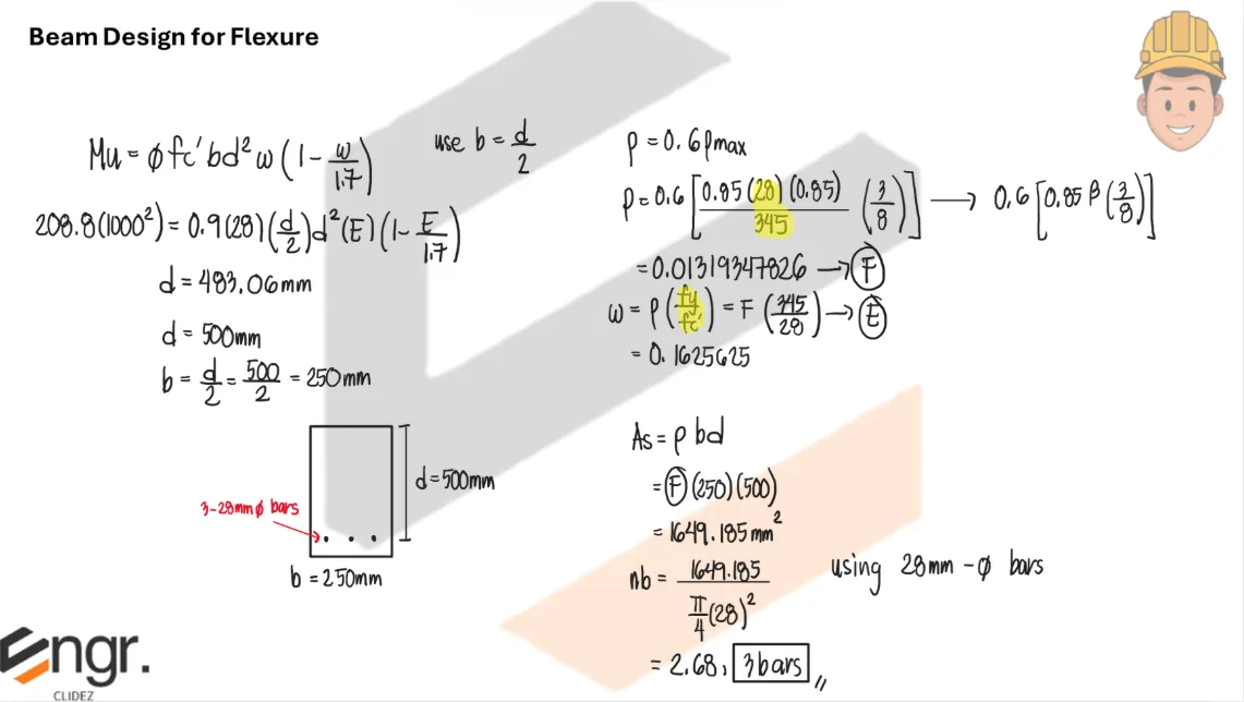
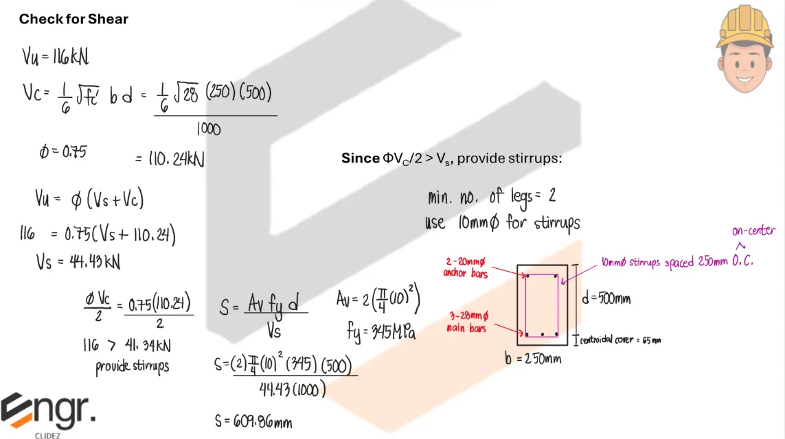
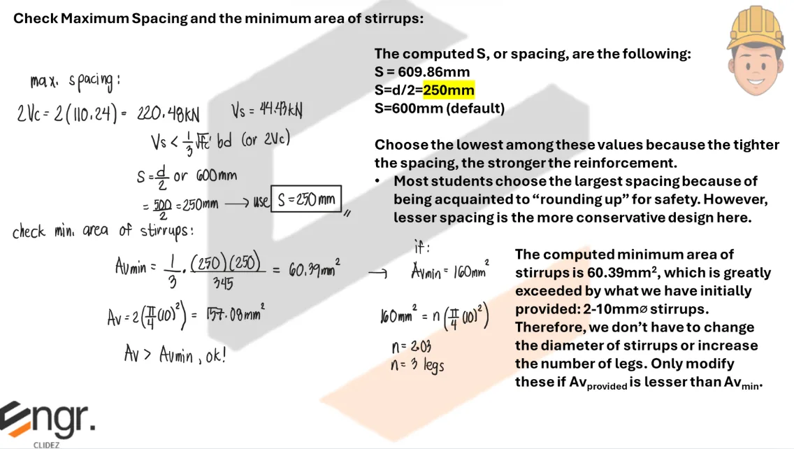
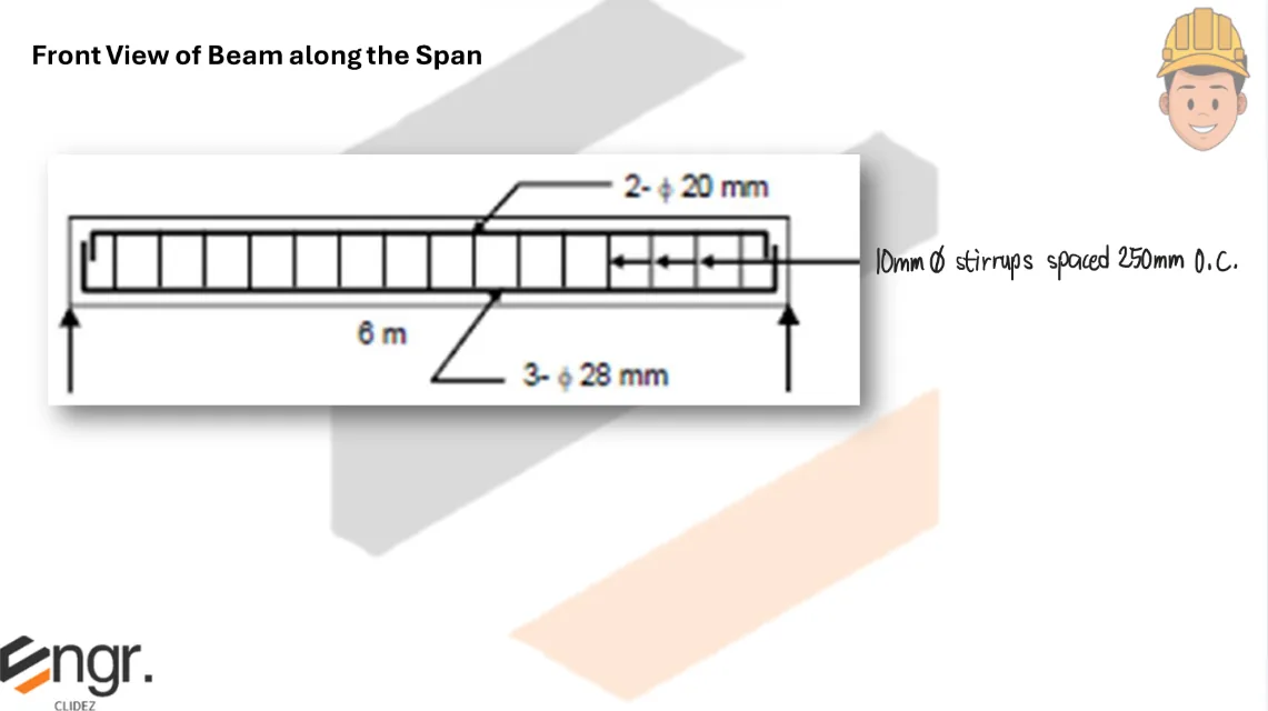
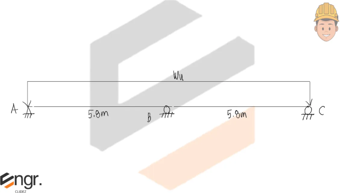
A 6m simply supported beam carries a uniform live load of 20kN/m and a dead load of 12kN/m (including its own weight).Use f'c=28MPa, fy=345MPa, b=d/2. Choose appropriate bar diameters and check for shear.
See images:
Problem (Design Problem):
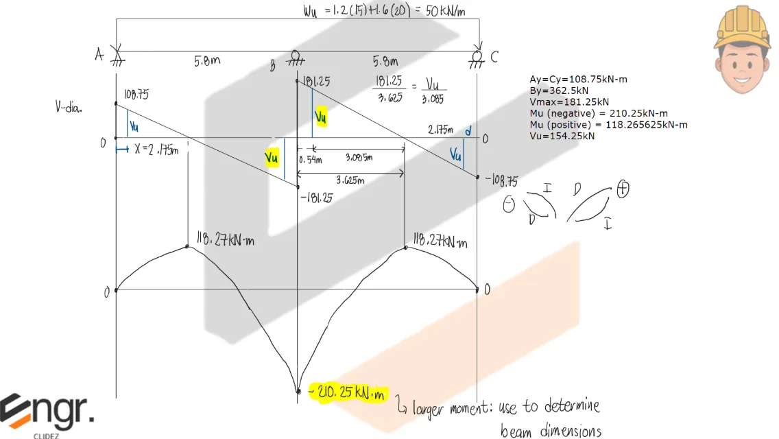
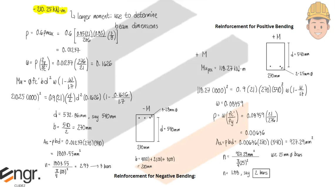
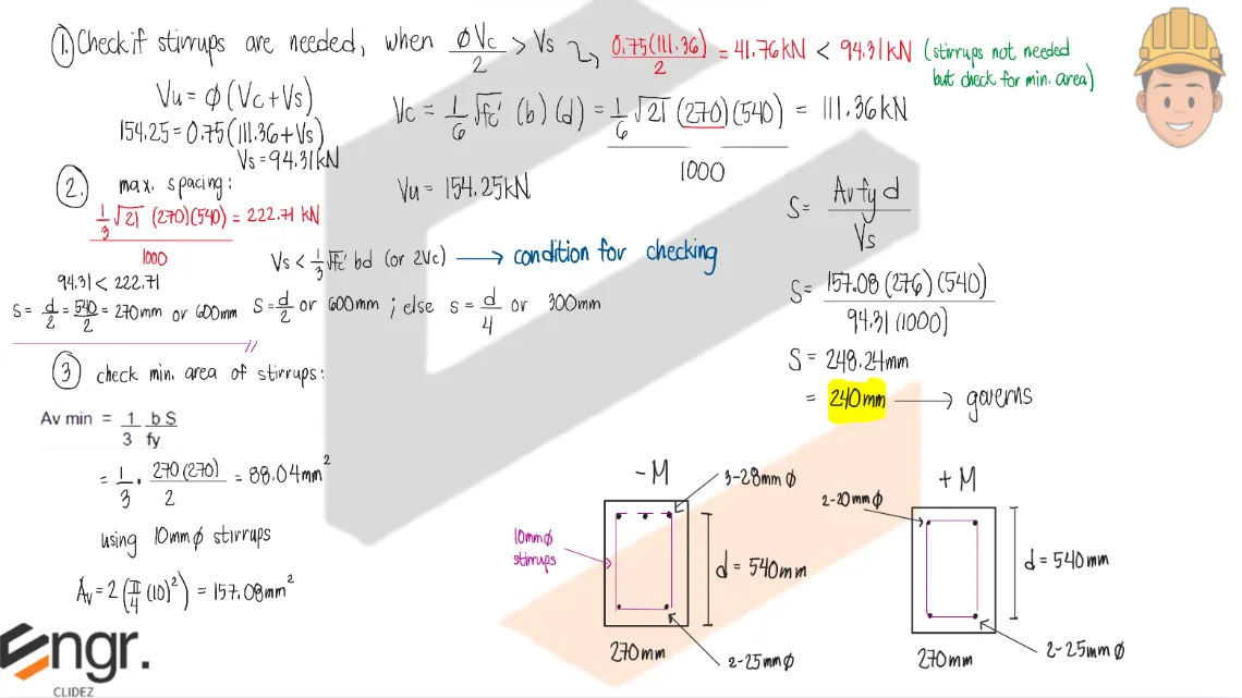
Design the beam shown to carry a service live load of 20kN/m and a dead load of 15kN/m (including its own weight). Use f'c=21MPa, fy=276MPa, b=d/2. The beam is to be reinforced for tension only. Check also for shear.
See images:
CE Board Nov. 2021
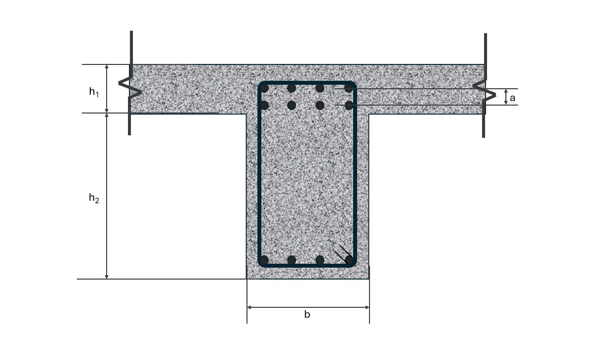
A beam has reinforcement at the top of 3 – 28 mm ∅ bars and at the bottom 5 – 28 mm ∅ bars. There are 3 legs of vertical stirrups as shown. The beam section has h1 = 110 mm (flange) and h2 = 490 mm (stem), bw = 350 mm, total h = 600 mm. Concrete cover to centroid of reinforcement = 70 mm. Stirrups: 10 mm ∅, spacing s = 100 mm. fc' = 27.5 MPa, fy = 415 MPa, fyv = 225 MPa.
Determine the shear strength of the stirrups, Vs.
Determine the shear strength of the concrete, Vc.
Determine the maximum allowable spacing of the stirrups.
#1 — Shear Strength of Stirrups (Vs)
Three legs of 10 mm ∅ stirrups; effective depth = h − cover to centroid:
A column 600 mm in diameter is reinforced with 8 – 25 mm ∅ bars and 12 mm ∅ spirals spaced at 100 mm on centers. φ = 0.75, fy = 413 MPa (main bars), fyt = 275 MPa (spirals), fc' = 30 MPa.
What is the nominal shear strength provided by the concrete?
What is the nominal shear strength provided by the shear reinforcement?
Find the shear stress in the column if Vu = 800 kN.
#1 — Nominal Shear Strength by Concrete (Vc)
For solid circular sections (§22.5.2.2): d = 0.8D = 0.8(600) = 480 mm, bw = D = 600 mm:
From the figure: h1 = 125 mm, h2 = 475 mm (total h = 600 mm). Bottom steel: 8 – 28 mm ∅ bars arranged in 2 layers of 4, with a clear distance of 55 mm between rows. Top steel: 4 – 28 mm ∅ bars. fc' = 28 MPa, fy = 415 MPa, fyt = 275 MPa. Tie diameter = 12 mm, φ = 0.75, clear concrete cover = 40 mm, maximum aggregate size = 20 mm.
Find the minimum width of beam "b" required to satisfy cover requirements.
Find the minimum width "b" for Vu = 600 kN with 12 mm ∅ ties at s = 50 mm.
If Vu = 450 kN with 12 mm ∅ ties at s = 70 mm, find the required minimum "b".
#1 — Minimum Width for Cover Requirements
Governing clear spacing (§25.2.1) — greatest of 25 mm, db = 28 mm, (4/3)(20) = 26.67 mm → 28 mm governs.
Beam BE is simply supported at B and E. S = 2.6 m (beam spacing), L = 5.3 m span. Slab thickness t = 100 mm. Beam: b = 250 mm, H = 400 mm. Effective cover to centroid of steel = 75 mm. fc' = 20.7 MPa, fy = 415 MPa, fyv = 275 MPa. Unit weight of concrete = 23.6 kN/m³. Superimposed DL = 2.6 kPa (slab weight NOT included). Live load = 3.6 kPa. Use U = 1.2DL + 1.6LL.
Which of the following gives the span moment (kN·m) at beam BE?
Which of the following gives the maximum shear force Vu (kN) at the critical section at support B?
Which of the following gives the nominal shear strength (kN) provided by the concrete?
A two-span beam subjected to shear and flexure only is reinforced as follows. At supports: 5 – 25 mm ∅ top bars, 3 – 25 mm ∅ bottom bars. At midspan: 3 – 25 mm ∅ top bars, 3 – 25 mm ∅ bottom bars. Lateral ties: 10 mm ∅. fc' = 27.5 MPa, fy = 415 MPa, fyt = 275 MPa. Beam: b × h = 350 × 450 mm, d = 375 mm, slab thickness = 100 mm. Use U = 1.2D + 1.6L.
What is the nominal shear capacity Vn (kN) at the supports if ties are 3-legged at s = 100 mm?
At midspan where shear is minimum, what is the theoretical maximum spacing of 2-leg lateral ties?
Calculate the ultimate moment capacity at the supports in kN·m.
Use the lesser (more restrictive): S = 352.6 mm → round down to:
\[ \boxed{S_{\max} = 350 \text{ mm}} \]
This is the theoretical maximum from Av,min requirements. In practice, the code maximum spacing of d/2 = 187.5 mm (Table 409.7.6.2.2) applies when stirrups are required, and would govern over 350 mm.
#3 — Ultimate Moment Capacity at Supports
As = 5 × π/4(25)² = 2454.37 mm² (5 top bars), b = 350 mm, d = 375 mm, β1 = 0.85
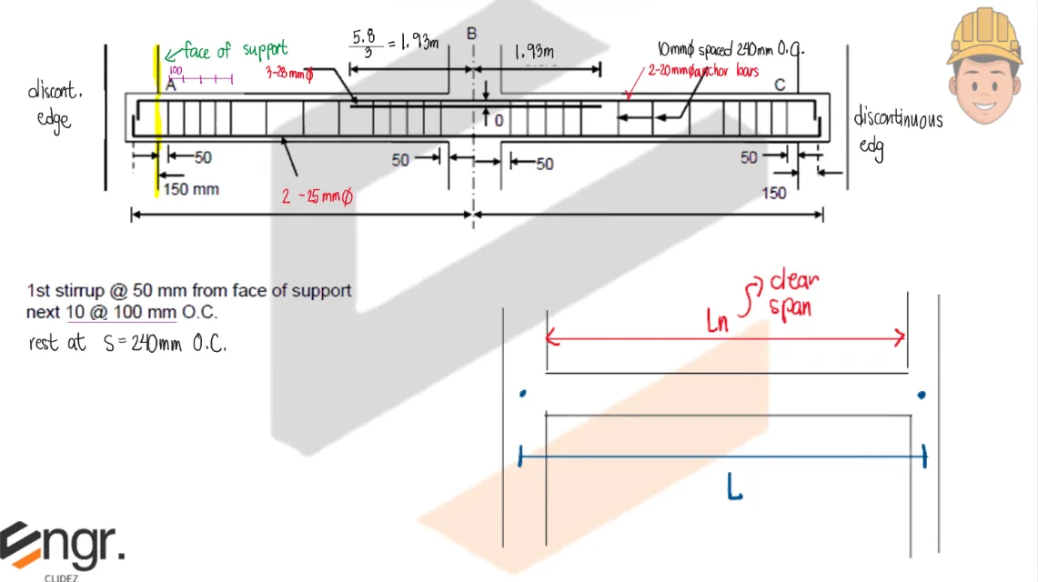
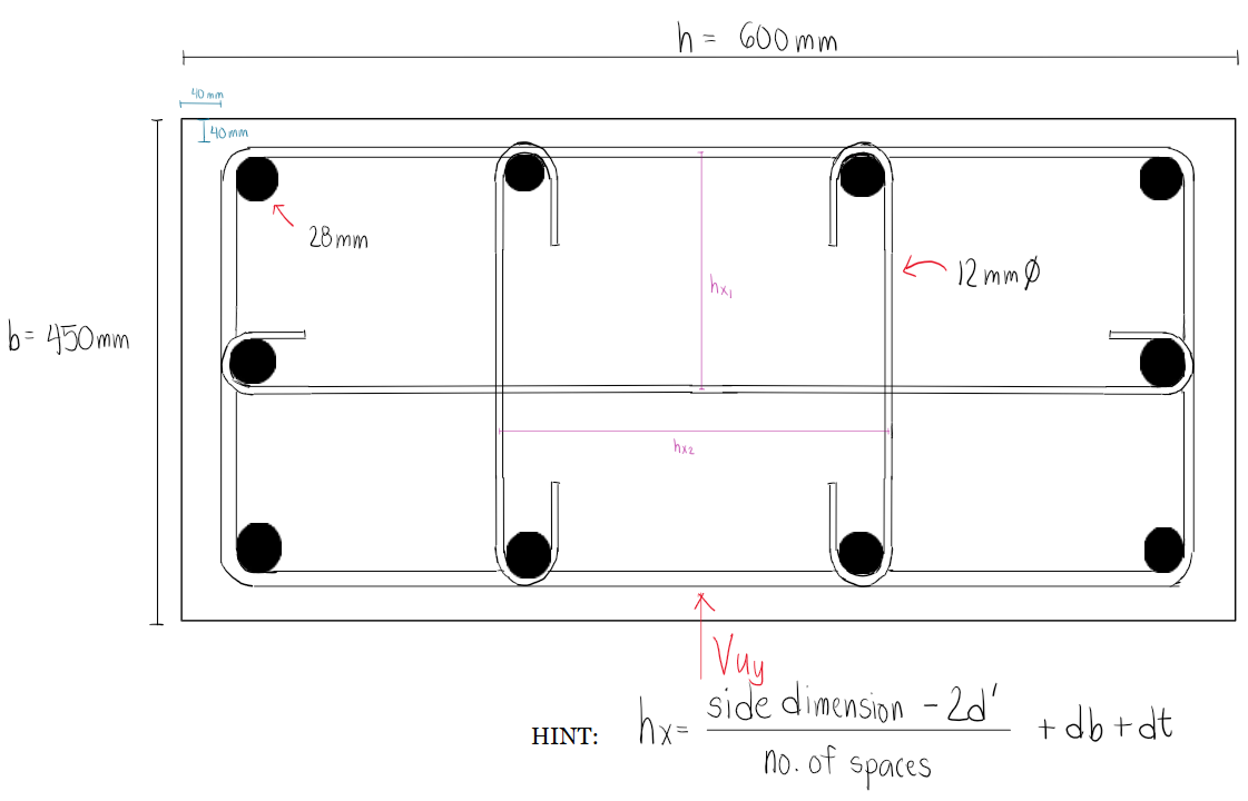
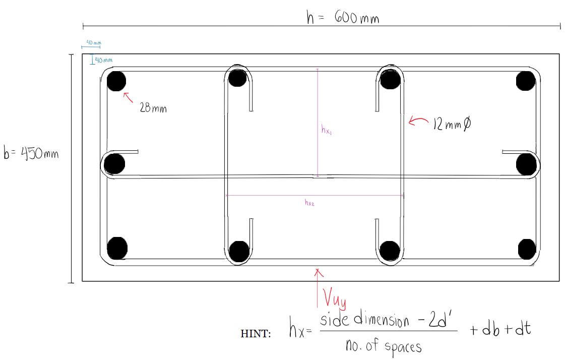
CE Board May 2010 The figure shows the shear force at the column section of a building with transverse confining reinforcement.
Clear cover of 12mm-dia. ties = 40mm fc'=27.5MPa fy=415MPa (for main bars) fyh=275MPa (for tie bars) The column shown in the figure is subjected to 480kN shear parallel to the short side. The nominal shear strength of concrete for shear parallel to the short side is 0.88MPa. Use 2001 NSCP for which the shear reduction factor is 0.85.
Calculate the nominal shear strength that must be provided by the lateral reinforcement.
362
672
346
187
What is the required spacing of the lateral reinforcement?
130
140
110
120
If the spacing of the lateral reinforcements is 100mm, what is the ultimate shear strength of the column for shear parallel to the short side?
578
570
562
596
Use the short-side shear direction and the tie layout in the figure. The concrete contribution is $V_c=0.88b_wd$, and the required tie contribution follows from $\phi(V_c+V_s)=V_u$.
Part 1. $V_s=V_u/\phi-V_c=\boxed{362\text{ kN}}$.
Part 2. For the multi-leg 12-mm tie, $V_s=A_vf_{yh}d/s$. Solving for spacing gives $s=\boxed{130\text{ mm}}$.
Part 3. With $s=100\text{ mm}$, recompute $V_s$, add $V_c$, and apply $\phi=0.85$. The resulting ultimate shear strength is $\boxed{578\text{ kN}}$.
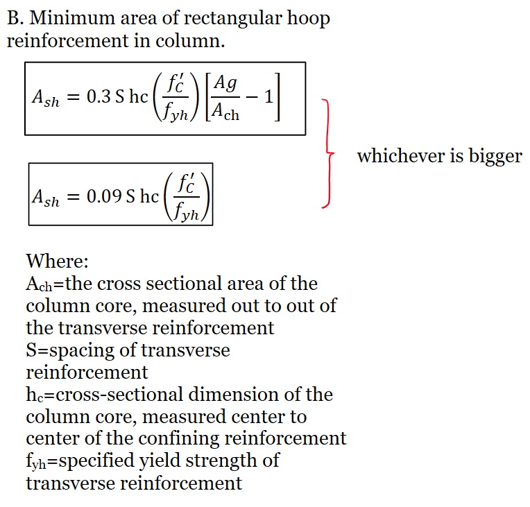
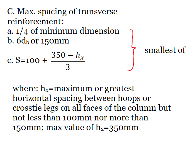
CE Board May 2010 The lateral reinforcement of the column shown is to be designed based on the special provisions for seismic design.
Which of the following gives the required spacing of lateral reinforcement for shear parallel to the short side of the column?
70
75
85
80
Which of the following gives the required spacing of lateral reinforcement for shear parallel to the long side of the column?
75
85
80
70
Which of the following gives the maximum spacing of lateral reinforcements?
112
124
103
98
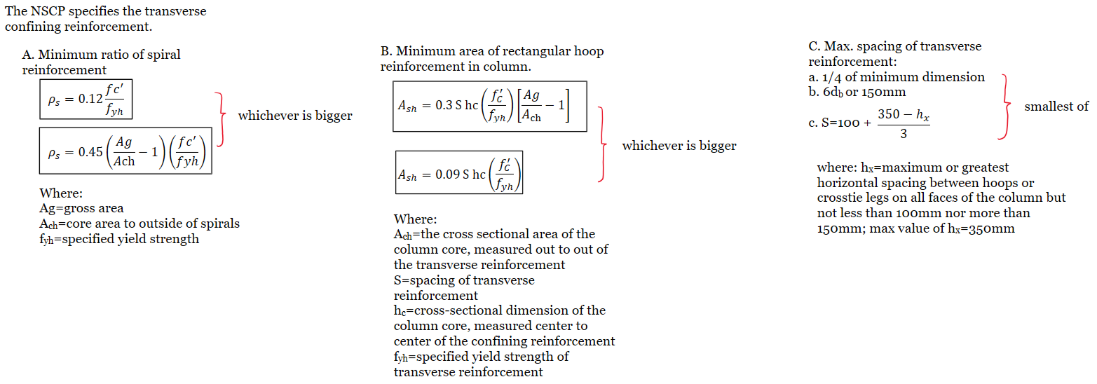
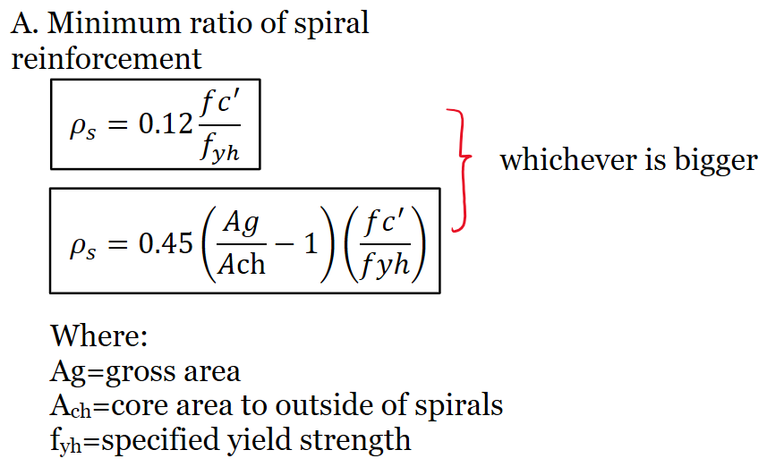
The seismic transverse-reinforcement rules require the smaller of $b_{\min}/4$, $6d_b$ (not over 150 mm), and $100+(350-h_x)/3$, in addition to satisfying the required shear-reinforcement area.
Part 1. Using the short-side shear demand and the provided hoop layout, $A_vf_{yh}d/V_s$ gives $\boxed{70\text{ mm}}$.
Part 2. Repeating the calculation for shear parallel to the long side gives $\boxed{75\text{ mm}}$.
Part 3. The largest permitted code spacing is $b_{\min}/4=450/4=112.5\text{ mm}$, reported as $\boxed{112\text{ mm}}$.
Question Bank: q26
PSAD - Reinforced Concrete / Shear and Moment Coefficients / Engr. Janclyde Espinosa (Clidez)
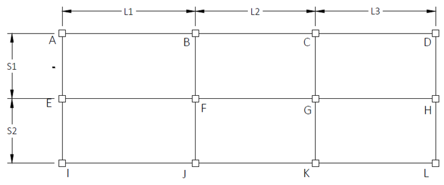
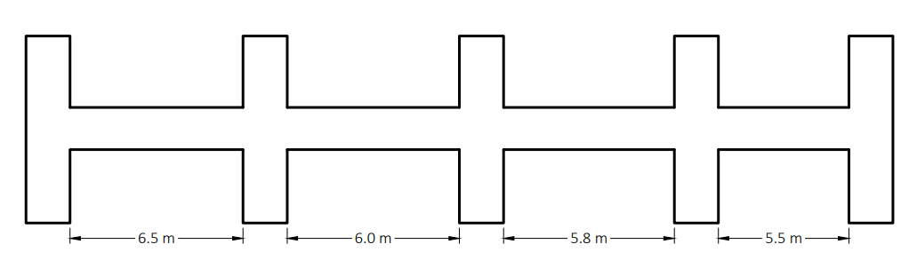
Given the following data for the floor plan shown Dead load = 3.6kPa (all weights included) Live load=5.4kPa Clear spans of beam, L1=L2=L3=6m Spacing of beams, S1=S2=2.5m Column dimensions=0.4mx0.4m
Determine the maximum positive moment at span FG due to factored dead load only.
24.3
19.29
20.25
17.64
What is the maximum negative moment at span EF due to factored live load?
77.76
43.2
60.21
69.12
If wu=30kN/m, compute the shear at G in span GH in kN.
103.5
96.6
117
134.55
Use the tributary width $S=2.5\text{ m}$ and $L=6\text{ m}$. For dead load only, $w_{uD}=1.2(3.6)(2.5)=10.8\text{ kN/m}$; for live load, $w_{uL}=1.6(5.4)(2.5)=21.6\text{ kN/m}$.
Part 1. The positive-moment coefficient at FG is $1/16$:
$M_u=w_{uD}L^2/16=10.8(6^2)/16=\boxed{24.3\text{ kN-m}}$.
Part 2. The negative-moment coefficient at EF is $1/10$:
$M_u=w_{uL}L^2/10=21.6(6^2)/10=\boxed{77.76\text{ kN-m}}$.
Part 3. Using the continuous-beam shear coefficient at G, $V_u=0.575w_uL=0.575(30)(6)=\boxed{103.5\text{ kN}}$.
CE Board Nov. 2021 A continuous beam is reinforced as shown: Given: As=8-20mm⌀ bars As'=4-20mm⌀ bars ds=10mm a=45mm f'c=34MPa Longitudinal steel, fyl=413MPa Transverse ties, fyv=275MPa Clear concrete cover=40mm b=350mm h1=100mm h2=400mm.
Calculate the shear strength (kN) provided by the concrete.
144.85
146.78
134.88
139.26
The 10mm diameter ties are spaced at 100mm on centers. What is the shear strength provided by the shear reinforcement?
180.35
160.27
176.34
150.89
What is the maximum allowable tie spacing?
340
345
350
355
Use the effective depth from the shown reinforcement to compute the concrete contribution, $V_c=0.17\sqrt{f'_c}b_wd$.
Part 1. Substitution of $f'_c=34\text{ MPa}$ and the section dimensions gives $V_c=\boxed{144.85\text{ kN}}$.
Part 2. For two-legged 10-mm ties at 100 mm, $V_s=A_vf_{yv}d/s=\boxed{180.35\text{ kN}}$.
Part 3. Apply the code maximum spacing limit for this beam and the calculated effective depth. The maximum permitted spacing is $\boxed{340\text{ mm}}$.
The design of a beam yields the following: As=5-28mm⌀ As'=3-28mm⌀ fc'=34MPa ds = 12mm⌀ ties fy = 413MPa fyv = 275MPa h1 = 110mm h2 = 490mm b = 375mm Effective cover to the centroid of tension steel = 75mm Shear strength reduction factor = 0.75
Which of the following most nearly gives the shear strength (kN) provided by the 12mm⌀ ties spaced at 100mm O.C.?
489
511
445
412
Which of the following most nearly gives the shear strength (kN) provided by the concrete section?
195
184
178
214
The beam is to be redesigned for a shear force of 455kN. Using 10mm⌀ ties spaced at 90mm O.C., how much is the required width (mm) of the beam?
450
400
380
320
### Shear strength of the reinforced-concrete beam
The overall depth is $110+490=600 \text{mm}$, so the effective depth is
$$d=600-75=525 \text{mm}.$$
From the tie layout, four vertical legs cross the shear plane. Thus for $12 \text{mm}$ ties,
$$A_v=4\left(\frac{\pi(12)^2}{4}\right)=452.4 \text{mm}^2.$$
The nominal tie contribution is
$$V_s=\frac{A_vf_{yv}d}{s},$$
and the design contribution for $s=100 \text{mm}$ is
$$phi V_s=0.75\frac{452.4(275)(525)}{100}=\boxed{489 \text{kN}}.$$
For normal-weight concrete,
$$V_c=0.17\sqrt{f'_c},b_wd,$$
so
$$V_c=0.17\sqrt{34}(375)(525)=\boxed{195 \text{kN}}.$$
For the redesign, use $10 \text{mm}$ ties at $90 \text{mm}$ spacing and solve
$$phileft[0.17\sqrt{34},bd+\frac{A_v(275)d}{90}\right]\ge455 \text{kN}.$$
Using the effective depth and four tie legs from the section, the required practical width is
$$bapprox\boxed{450 \text{mm}}.$$
The width is rounded up to the next listed safe size.
Question Bank: q145
PSAD - Reinforced Concrete / Shear and Moment Coefficients / Engr. Janclyde Espinosa (Clidez)
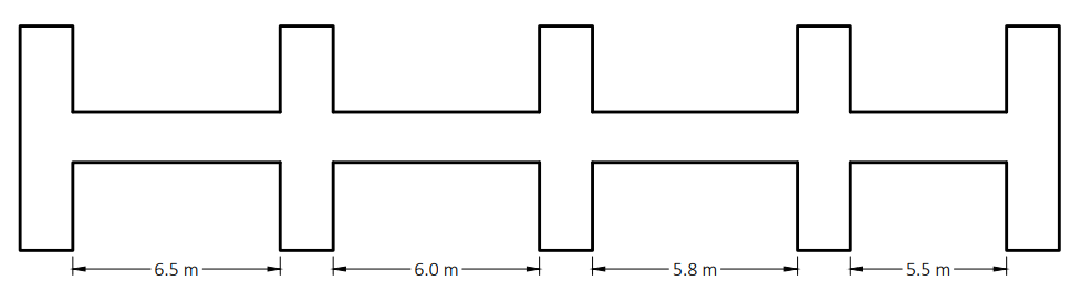
For the beam shown, the ultimate and factored loads are the following: UDL = 12kN/m ULL = 12.5kN/m
Determine the maximum positive moment at span BC in kN-m
55
49
65
59
Determine the maximum moment at D of beam DE in kN-m
78
82
67
53
Determine the maximum shear (kN) at B in beam AB
92
79
84
96
### Continuous-beam coefficients
First obtain the factored uniform load from the dead and live components:
$$w_u=1.4(12)+1.7(12.5)=38.05 \text{kN/m}.$$
Use the moment and shear coefficients for the applicable continuous-beam condition, with the clear spans shown. Substitution of the span lengths gives
$$M_{+,BC}\approx\boxed{55 \text{kN}\!\cdot\!\text{m}},$$
$$M_{D,DE}\approx\boxed{78 \text{kN}\!\cdot\!\text{m}},$$
and
$$V_{B,AB}\approx\boxed{92 \text{kN}}.$$
The signs of the moments identify positive span moment at $BC$ and negative support moment at $D$; the choices ask for their magnitudes.