CE Board Exam Randomizer

⬅ Back to Subject Topics

Axial Strain | Stress-Strain Curve

Problem:

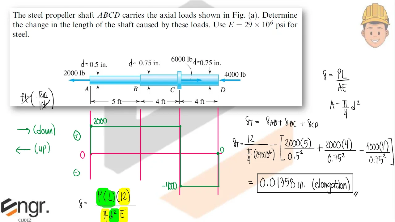
The steel propeller shaft ABCD carries the axial loads shown. Determine the change in length of the shaft caused by these loads.
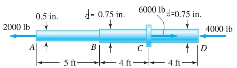
Axial Strain and Deformation | Mechanics of Deformable Bodies – Problem 1: – Diagram Axial Strain and Deformation | Mechanics of Deformable Bodies – Problem 1: – Diagram Axial Strain and Deformation | Mechanics of Deformable Bodies – Problem 1: – Diagram

See images:

Axial Strain and Deformation | Mechanics of Deformable Bodies – Problem 1: – Diagram Axial Strain and Deformation | Mechanics of Deformable Bodies – Problem 1: – Diagram Axial Strain and Deformation | Mechanics of Deformable Bodies – Problem 1: – Diagram Axial Strain and Deformation | Mechanics of Deformable Bodies – Problem 1: – Diagram

Problem:

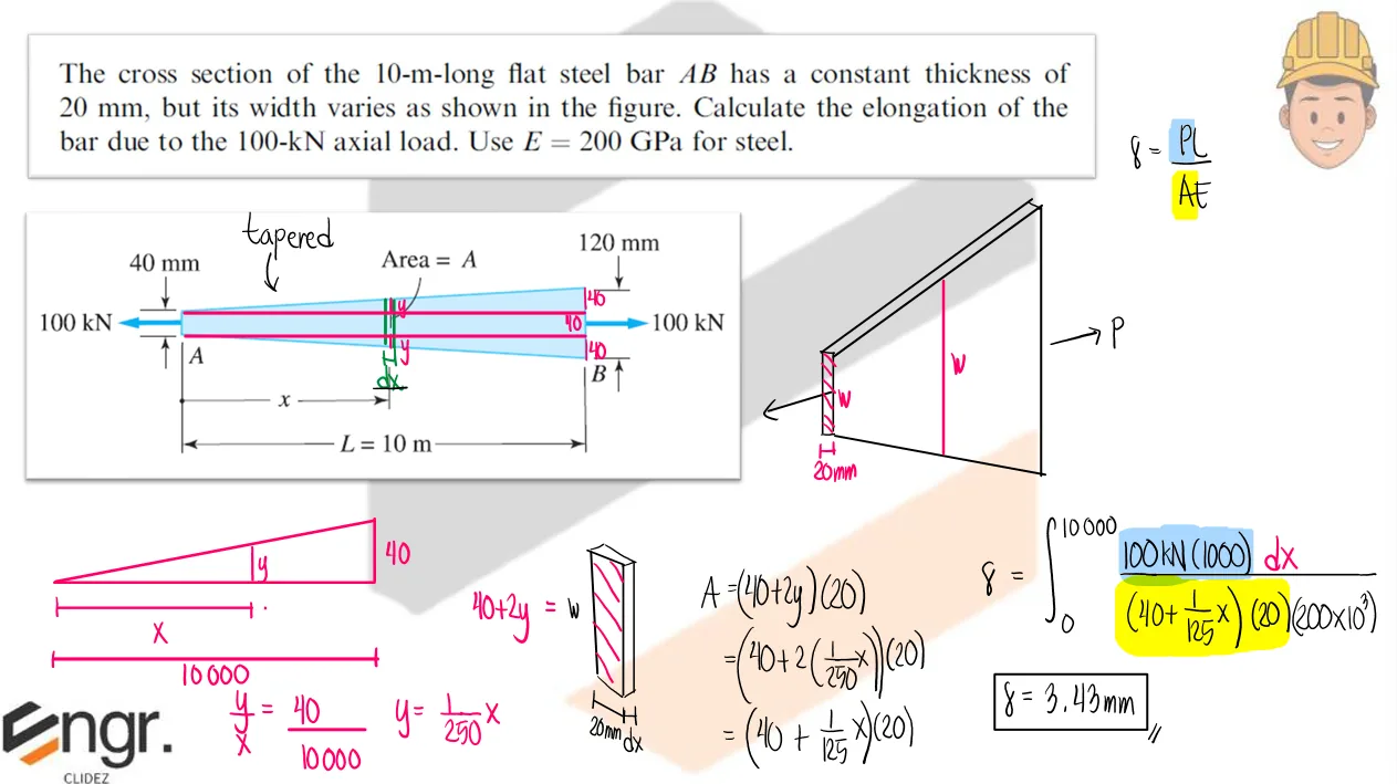
The cross section of the 10-m-long flat steel bar AB has a constant thickness of 20mm, but its width varies as shown in the figure. Calculate the elongation of the bar due to the 100-kN axial load. Use E=200GPa for steel.
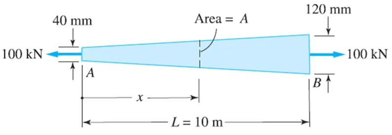
Axial Strain and Deformation | Mechanics of Deformable Bodies – Problem 2: – Diagram Axial Strain and Deformation | Mechanics of Deformable Bodies – Problem 2: – Diagram Axial Strain and Deformation | Mechanics of Deformable Bodies – Problem 2: – Diagram

See images:

Axial Strain and Deformation | Mechanics of Deformable Bodies – Problem 2: – Diagram Axial Strain and Deformation | Mechanics of Deformable Bodies – Problem 2: – Diagram Axial Strain and Deformation | Mechanics of Deformable Bodies – Problem 2: – Diagram Axial Strain and Deformation | Mechanics of Deformable Bodies – Problem 2: – Diagram

Problem:

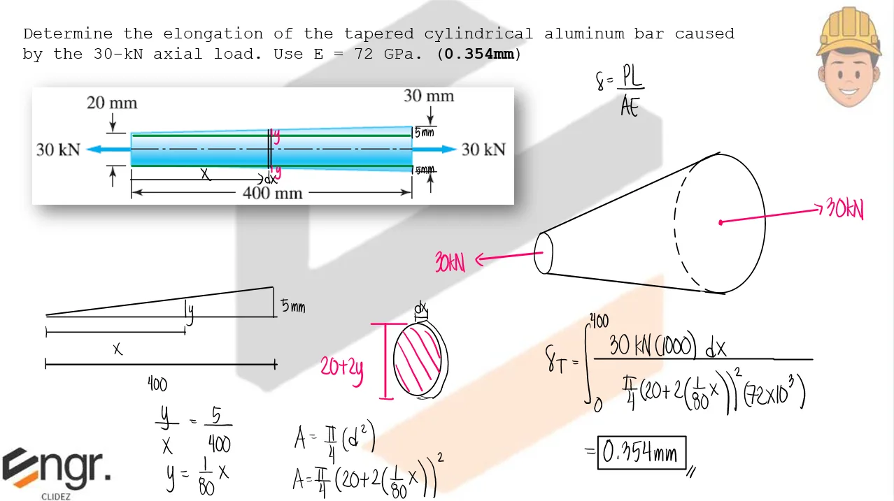
Determine the elongation of the tapered cylindrical aluminum bar caused by the 30-kN axial load. Use E = 72GPa.
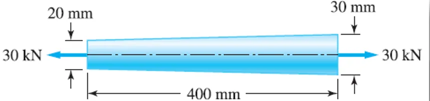
Axial Strain and Deformation | Mechanics of Deformable Bodies – Problem 3: – Diagram Axial Strain and Deformation | Mechanics of Deformable Bodies – Problem 3: – Diagram Axial Strain and Deformation | Mechanics of Deformable Bodies – Problem 3: – Diagram

See images:

Axial Strain and Deformation | Mechanics of Deformable Bodies – Problem 3: – Diagram Axial Strain and Deformation | Mechanics of Deformable Bodies – Problem 3: – Diagram Axial Strain and Deformation | Mechanics of Deformable Bodies – Problem 3: – Diagram Axial Strain and Deformation | Mechanics of Deformable Bodies – Problem 3: – Diagram

Problem:

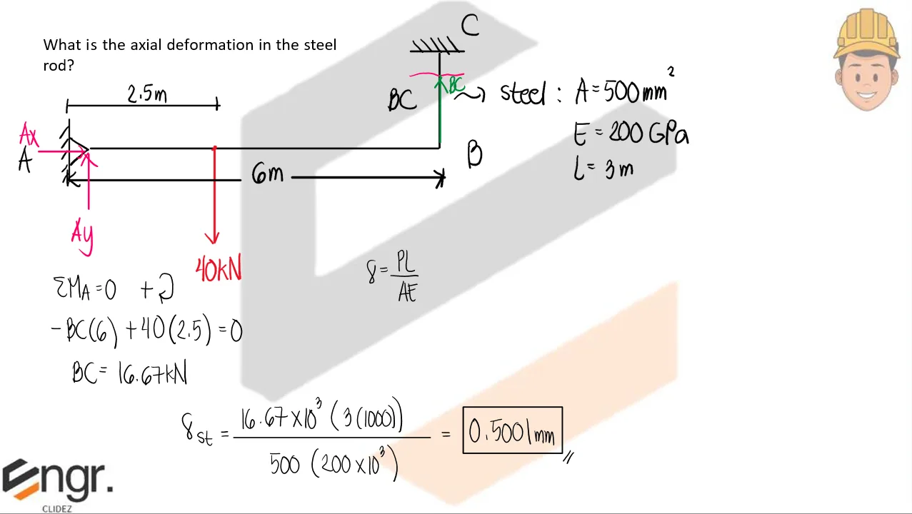
Determine the axial deformation in the steel rod.
Axial Strain and Deformation | Mechanics of Deformable Bodies – Problem 4: – Diagram Axial Strain and Deformation | Mechanics of Deformable Bodies – Problem 4: – Diagram Axial Strain and Deformation | Mechanics of Deformable Bodies – Problem 4: – Diagram

See images:

Axial Strain and Deformation | Mechanics of Deformable Bodies – Problem 4: – Diagram Axial Strain and Deformation | Mechanics of Deformable Bodies – Problem 4: – Diagram Axial Strain and Deformation | Mechanics of Deformable Bodies – Problem 4: – Diagram Axial Strain and Deformation | Mechanics of Deformable Bodies – Problem 4: – Diagram

Problem:

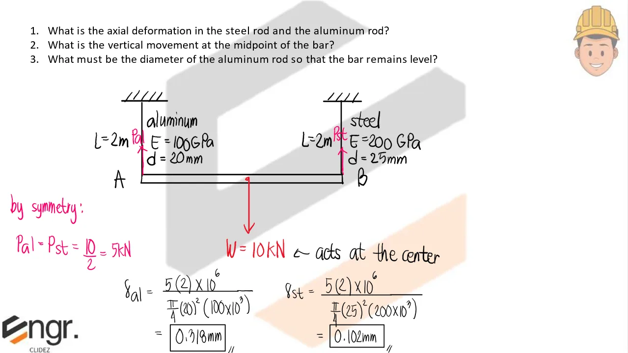
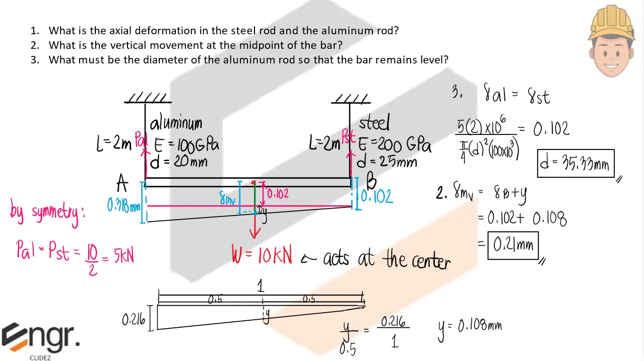
A rigid bar AB is supported at its ends by an aluminum and steel rod, respectively, at the left and right supports, respectively. If the bar weighs 10kN and given the following properties:
Aluminum: E=100GPa, d=20mm, L=2m
Steel: E=200GPa, d=25mm, L=2m
Determine the following:
a. What is the axial deformation in the steel rod and the aluminum rod?
b. What is the vertical movement at the midpoint of the bar?
c. What must be the diameter of the aluminum rod so that the bar remains level?

Axial Strain and Deformation | Mechanics of Deformable Bodies – Problem 5: – Diagram Axial Strain and Deformation | Mechanics of Deformable Bodies – Problem 5: – Diagram Axial Strain and Deformation | Mechanics of Deformable Bodies – Problem 5: – Diagram

See images:

Axial Strain and Deformation | Mechanics of Deformable Bodies – Problem 5: – Diagram Axial Strain and Deformation | Mechanics of Deformable Bodies – Problem 5: – Diagram Axial Strain and Deformation | Mechanics of Deformable Bodies – Problem 5: – Diagram Axial Strain and Deformation | Mechanics of Deformable Bodies – Problem 5: – Diagram

Problem:

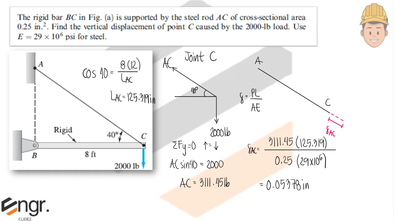
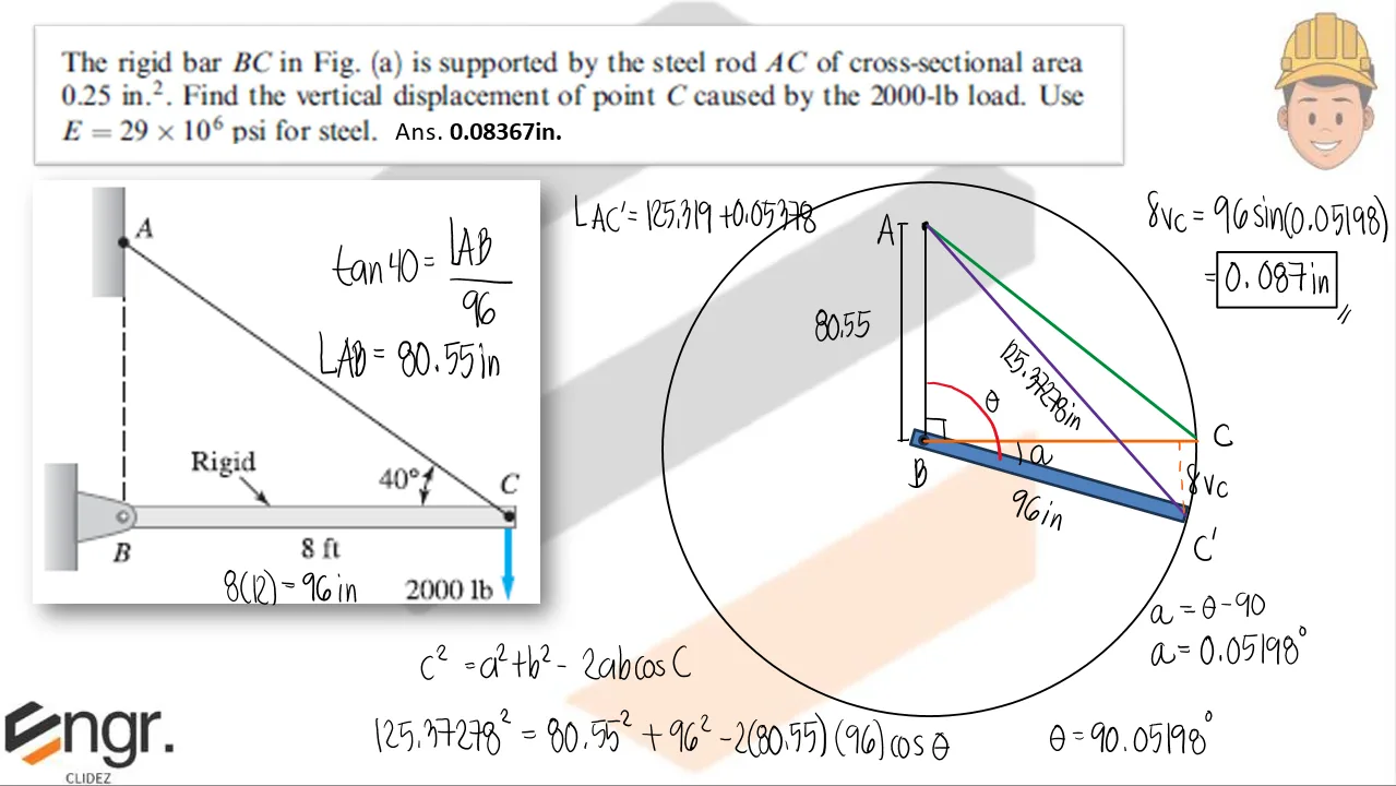
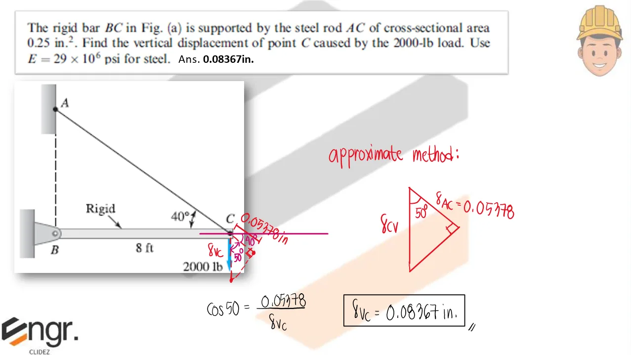
The rigid bar BC is supported by the steel rod AC of cross-sectional area 0.25in2. Find the vertical displacement of point C caused by the 2000-lb load. Use E=29x106psi for steel.
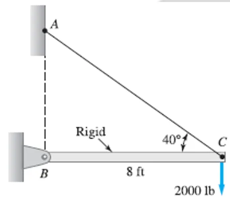
Axial Strain and Deformation | Mechanics of Deformable Bodies – Problem 6: – Diagram Axial Strain and Deformation | Mechanics of Deformable Bodies – Problem 6: – Diagram Axial Strain and Deformation | Mechanics of Deformable Bodies – Problem 6: – Diagram

See images:

Axial Strain and Deformation | Mechanics of Deformable Bodies – Problem 6: – Diagram Axial Strain and Deformation | Mechanics of Deformable Bodies – Problem 6: – Diagram Axial Strain and Deformation | Mechanics of Deformable Bodies – Problem 6: – Diagram Axial Strain and Deformation | Mechanics of Deformable Bodies – Problem 6: – Diagram

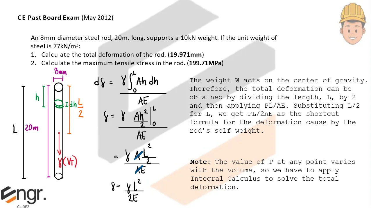
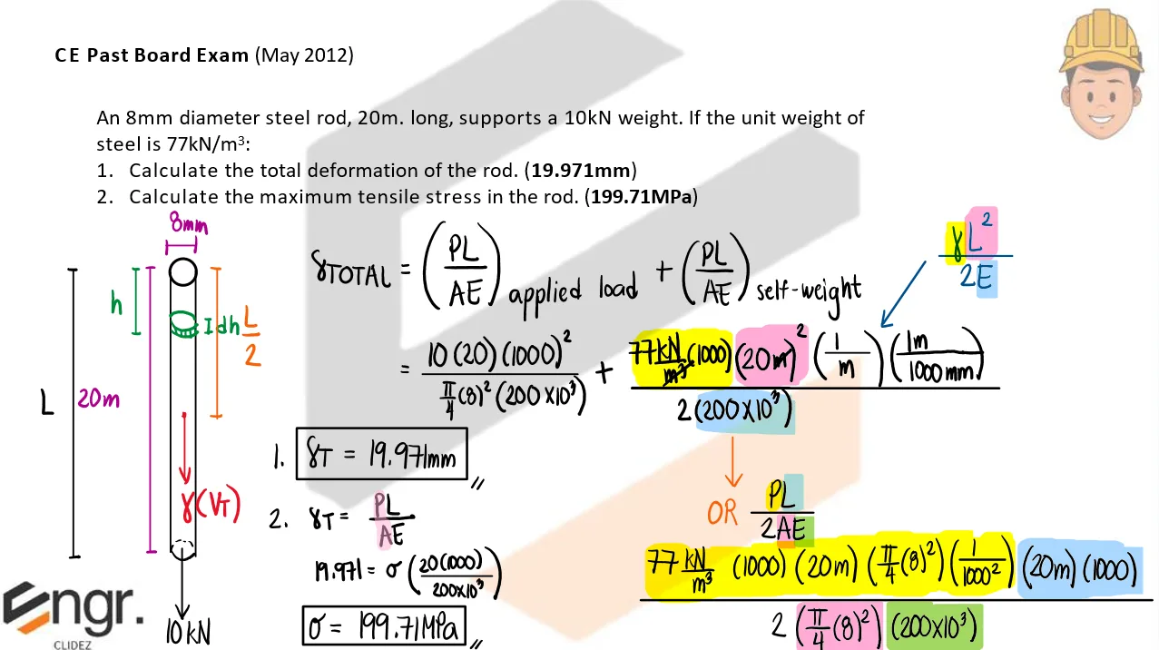
Problem: CE Past Board Exam (May 2012)

An 8mm diameter steel rod, 20m. long, supports a 10kN weight. If the unit weight of steel is 77kN/m3,
a. Calculate the total deformation of the rod.
b. Calculate the maximum tensile stress in the rod.

Axial Strain and Deformation | Mechanics of Deformable Bodies – Problem 7: CE Past Board Exam (May 2012) – Diagram Axial Strain and Deformation | Mechanics of Deformable Bodies – Problem 7: CE Past Board Exam (May 2012) – Diagram Axial Strain and Deformation | Mechanics of Deformable Bodies – Problem 7: CE Past Board Exam (May 2012) – Diagram

See images:

Axial Strain and Deformation | Mechanics of Deformable Bodies – Problem 7: CE Past Board Exam (May 2012) – Diagram Axial Strain and Deformation | Mechanics of Deformable Bodies – Problem 7: CE Past Board Exam (May 2012) – Diagram Axial Strain and Deformation | Mechanics of Deformable Bodies – Problem 7: CE Past Board Exam (May 2012) – Diagram Axial Strain and Deformation | Mechanics of Deformable Bodies – Problem 7: CE Past Board Exam (May 2012) – Diagram

Problem:

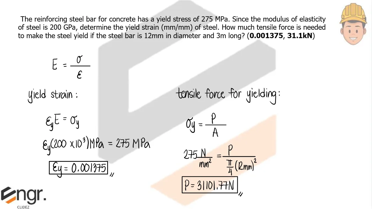
The reinforcing steel bar for concrete has a yield stress of 275MPa. Since the modulus of elasticity of steel is 200GPa, determine the yield strain of steel. How much tensile force is needed to make the steel yield if the steel bar is 12mm in diameter and 3m long?

Axial Strain and Deformation | Mechanics of Deformable Bodies – Problem 8: – Diagram Axial Strain and Deformation | Mechanics of Deformable Bodies – Problem 8: – Diagram Axial Strain and Deformation | Mechanics of Deformable Bodies – Problem 8: – Diagram

See images:

Axial Strain and Deformation | Mechanics of Deformable Bodies – Problem 8: – Diagram Axial Strain and Deformation | Mechanics of Deformable Bodies – Problem 8: – Diagram Axial Strain and Deformation | Mechanics of Deformable Bodies – Problem 8: – Diagram Axial Strain and Deformation | Mechanics of Deformable Bodies – Problem 8: – Diagram

Problem:

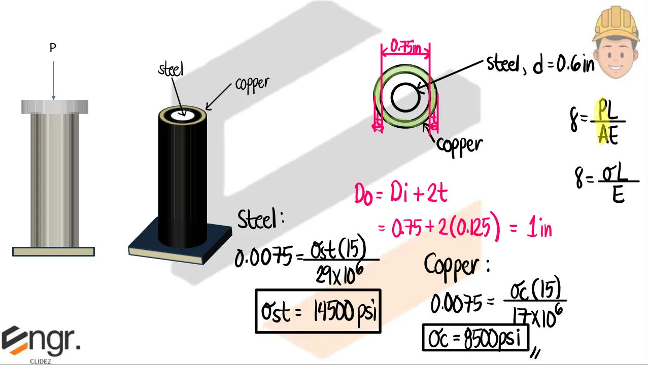
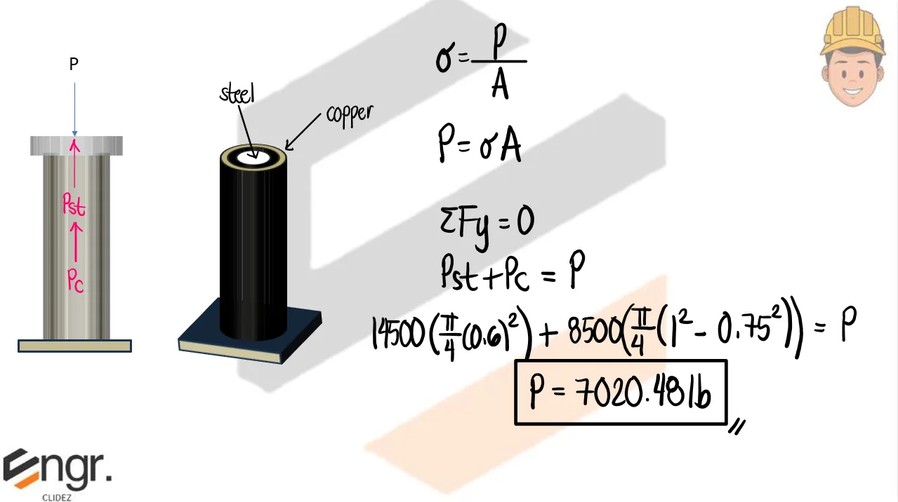
The steel rod is placed inside the copper tube, the length of each being exactly 15in. If the assembly is compressed by 0.0075in., determine the stress in each component and the applied force P. The moduli of elasticity are 29x106psi for steel and 17x106psi for copper. The diameter of the steel rod is 0.6in. The inner diameter of the copper tube is 0.75in and its thickness is 0.125in.
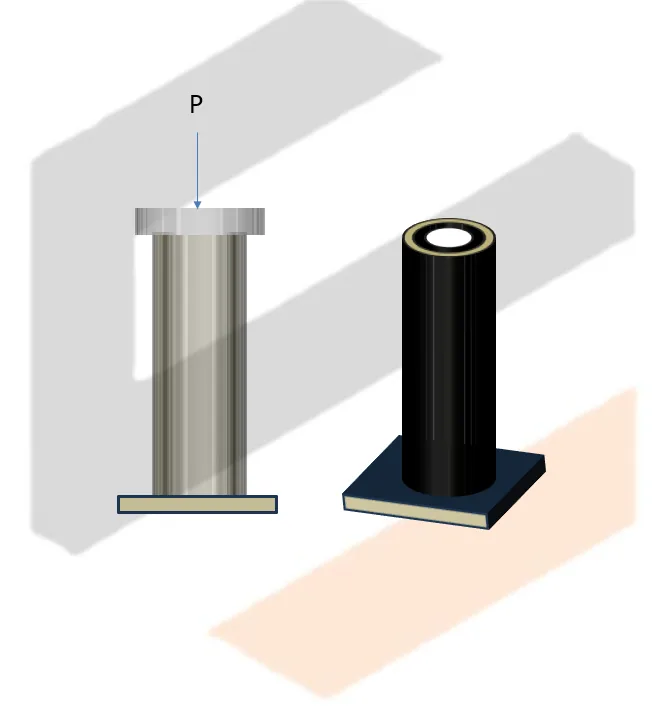
Axial Strain and Deformation | Mechanics of Deformable Bodies – Problem 9: – Diagram Axial Strain and Deformation | Mechanics of Deformable Bodies – Problem 9: – Diagram Axial Strain and Deformation | Mechanics of Deformable Bodies – Problem 9: – Diagram

See images:

Axial Strain and Deformation | Mechanics of Deformable Bodies – Problem 9: – Diagram Axial Strain and Deformation | Mechanics of Deformable Bodies – Problem 9: – Diagram Axial Strain and Deformation | Mechanics of Deformable Bodies – Problem 9: – Diagram Axial Strain and Deformation | Mechanics of Deformable Bodies – Problem 9: – Diagram

Problem:

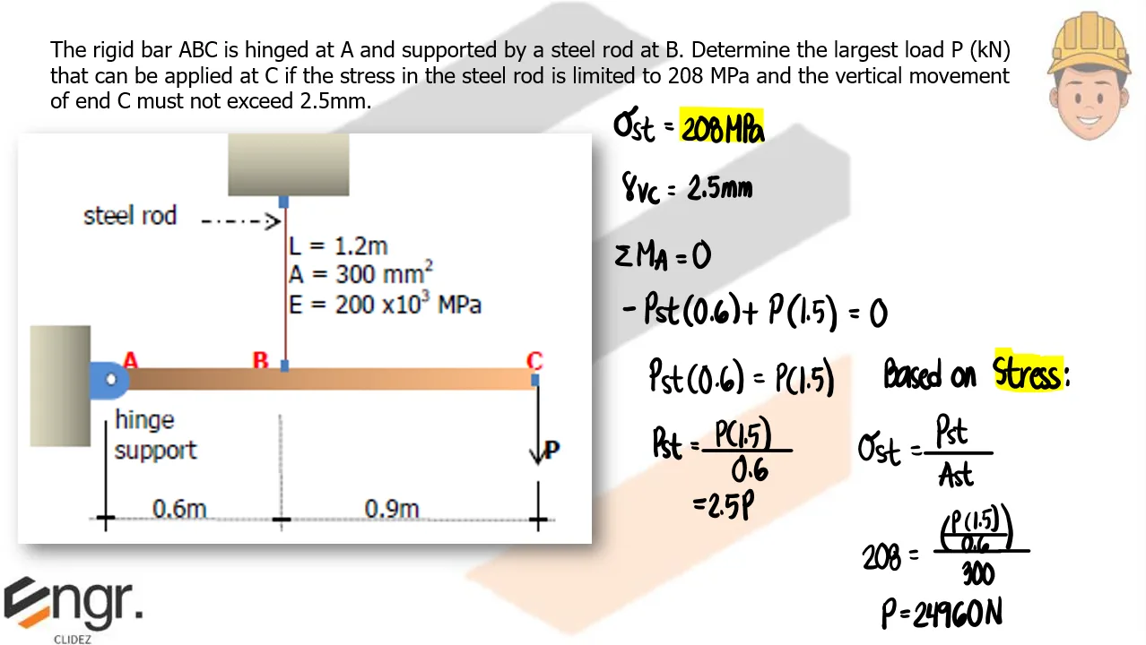
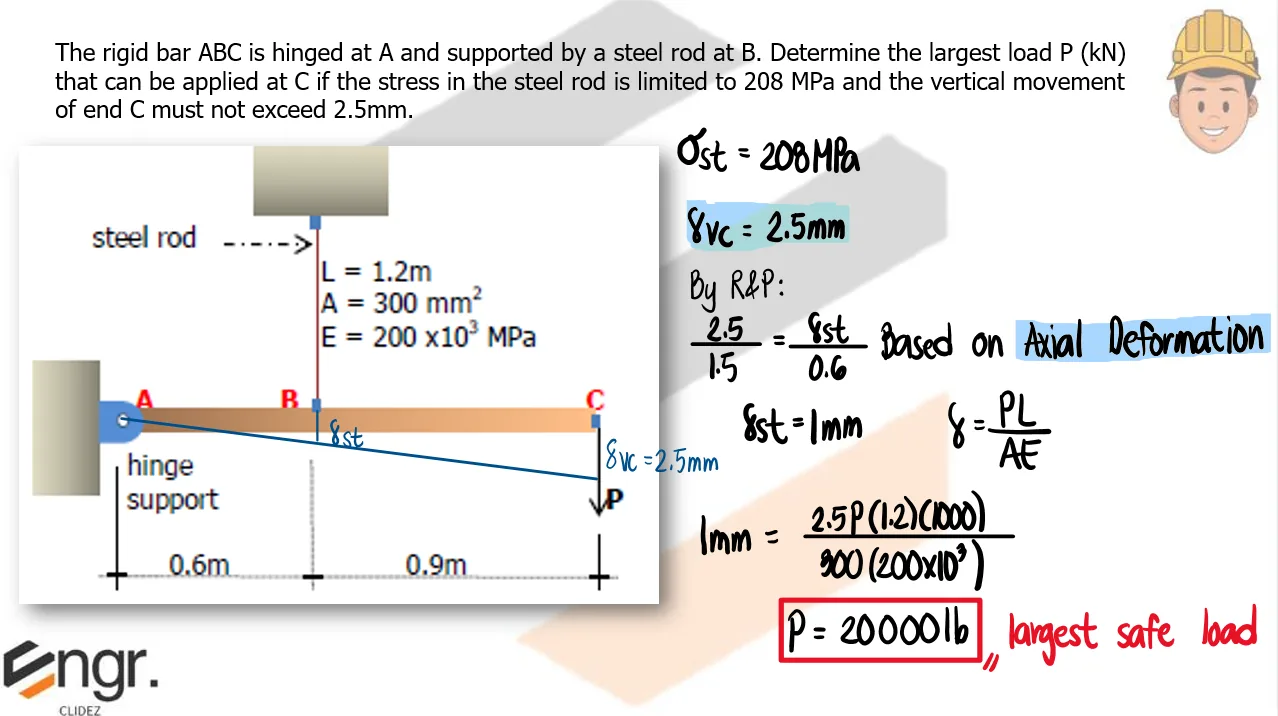
The rigid bar ABC is hinged at A and supported by a steel rod at B. Determine the largest load P (kN) that can be applied at C if the stress in the steel rod is limited to 208 MPa and the vertical movement of end C must not exceed 2.5mm.
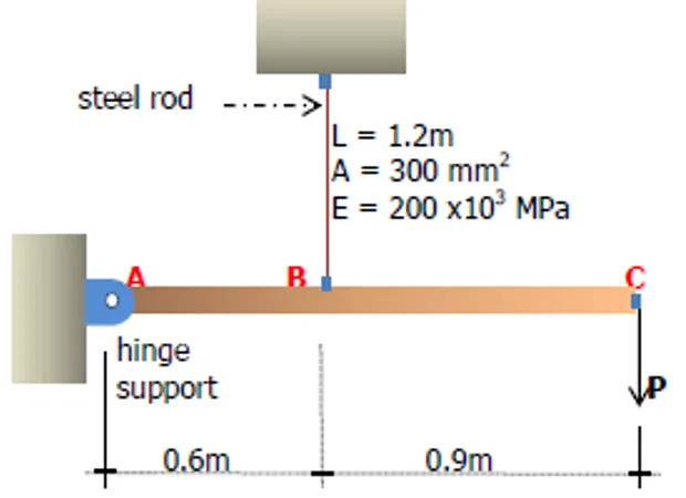
Axial Strain and Deformation | Mechanics of Deformable Bodies – Problem 10: – Diagram Axial Strain and Deformation | Mechanics of Deformable Bodies – Problem 10: – Diagram Axial Strain and Deformation | Mechanics of Deformable Bodies – Problem 10: – Diagram

See images:

Axial Strain and Deformation | Mechanics of Deformable Bodies – Problem 10: – Diagram Axial Strain and Deformation | Mechanics of Deformable Bodies – Problem 10: – Diagram Axial Strain and Deformation | Mechanics of Deformable Bodies – Problem 10: – Diagram Axial Strain and Deformation | Mechanics of Deformable Bodies – Problem 10: – Diagram

Problem:

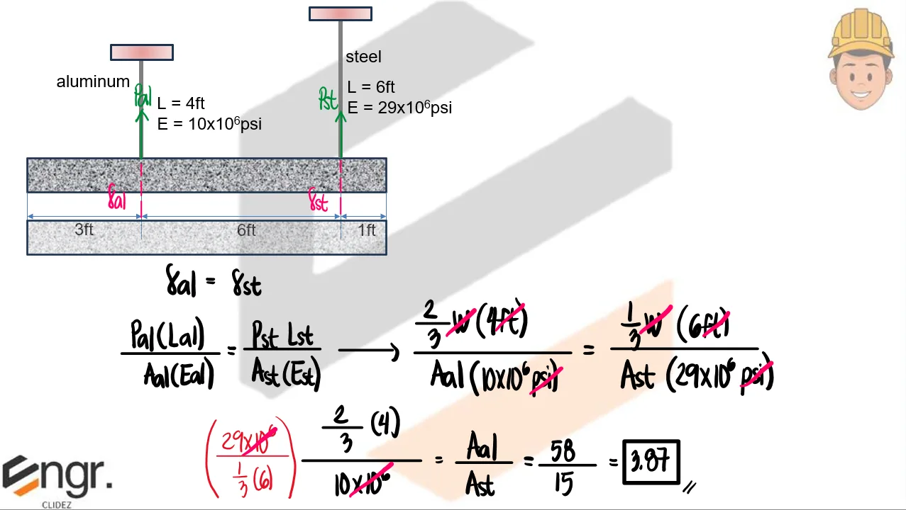
A uniform concrete slab of total weight W is to be attached to two rods whose lower ends are on the same level. Determine the ratio of the areas of the rods (aluminum to steel) so that the slab will remain level.
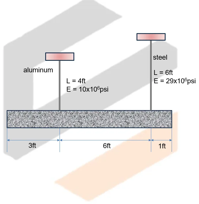
Axial Strain and Deformation | Mechanics of Deformable Bodies – Problem 11: – Diagram Axial Strain and Deformation | Mechanics of Deformable Bodies – Problem 11: – Diagram Axial Strain and Deformation | Mechanics of Deformable Bodies – Problem 11: – Diagram

See images:

Axial Strain and Deformation | Mechanics of Deformable Bodies – Problem 11: – Diagram Axial Strain and Deformation | Mechanics of Deformable Bodies – Problem 11: – Diagram Axial Strain and Deformation | Mechanics of Deformable Bodies – Problem 11: – Diagram Axial Strain and Deformation | Mechanics of Deformable Bodies – Problem 11: – Diagram

Problem:

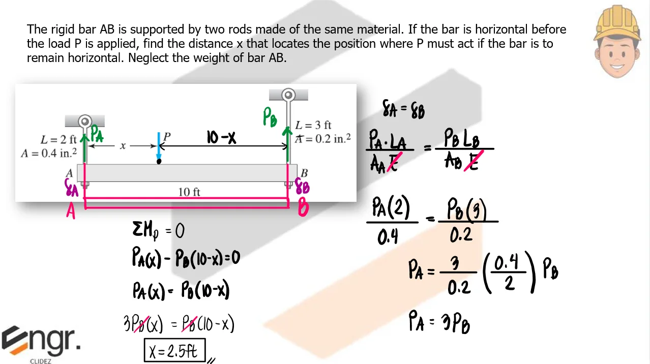
The rigid bar AB is supported by two rods made of the same material. If the bar is horizontal before the load P is applied, find the distance x that locates the position where P must act if the bar is to remain horizontal. Neglect the weight of bar AB.
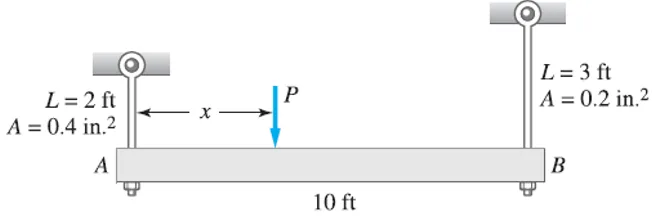
Axial Strain and Deformation | Mechanics of Deformable Bodies – Problem 12: – Diagram Axial Strain and Deformation | Mechanics of Deformable Bodies – Problem 12: – Diagram Axial Strain and Deformation | Mechanics of Deformable Bodies – Problem 12: – Diagram

See images:

Axial Strain and Deformation | Mechanics of Deformable Bodies – Problem 12: – Diagram Axial Strain and Deformation | Mechanics of Deformable Bodies – Problem 12: – Diagram Axial Strain and Deformation | Mechanics of Deformable Bodies – Problem 12: – Diagram Axial Strain and Deformation | Mechanics of Deformable Bodies – Problem 12: – Diagram

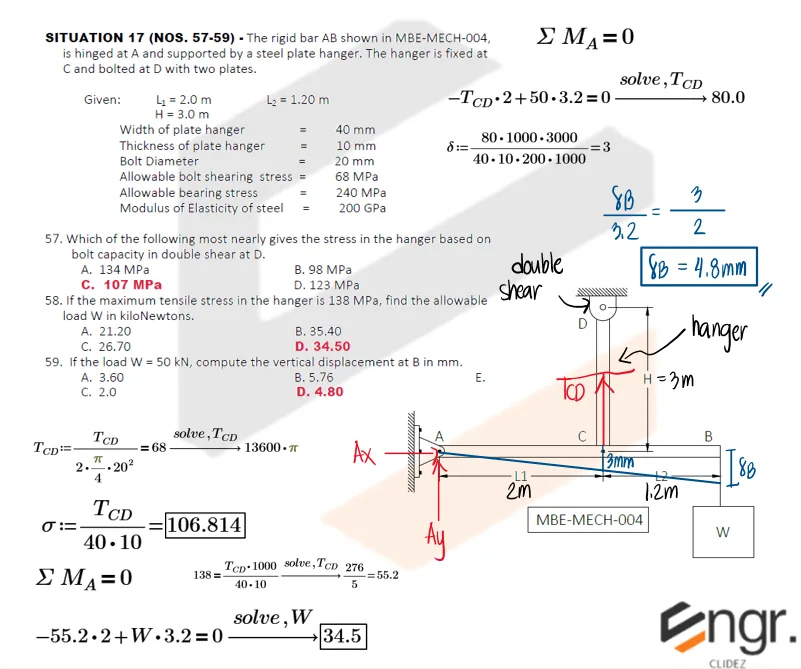
Problem: Rigid Bar Supported by Plate Hanger

The rigid bar AB shown below is hinged at A and supported by a steel plate hanger. The hanger is fixed at C and bolted at D with two plates.

Given:
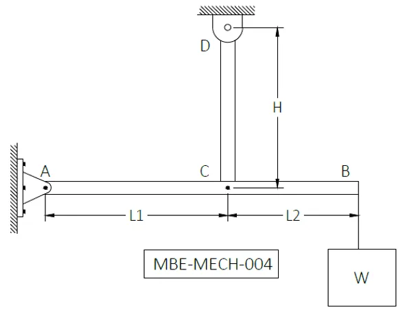
Axial Strain and Deformation | Mechanics of Deformable Bodies - Problem 13: Rigid Bar Supported by Plate Hanger - Diagram
  1. Which of the following most nearly gives the stress in the hanger based on bolt capacity in double shear at D?
    1. 134 MPa
    2. 98 MPa
    3. 107 MPa
    4. 123 MPa
  2. If the maximum tensile stress in the hanger is 138 MPa, find the allowable load W in kilonewtons.
    1. 21.20
    2. 35.40
    3. 26.70
    4. 34.50
  3. If the load W = 50 kN, compute vertical displacement at B in mm.
    1. 3.60
    2. 5.76
    3. 2.0
    4. 4.80

See images:

Axial Strain and Deformation | Mechanics of Deformable Bodies - Problem 13: Rigid Bar Supported by Plate Hanger - Solution

Exam Generator Problems

Additional board-style practice items for this topic.

Question Bank: q4

PSAD - Mechanics of Deformable Bodies / Axial Stress and Strain / Engr. Janclyde Espinosa (Clidez)

CE Board Nov. 2024
A flagpole is supported by four flexible steel cables. At the top of the pole, a force of 10kN is applied toward the positive x-direction. The diameter of cable AE is 16mm.
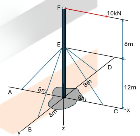
q4

Calculate the tensile stress in cable AE.

  1. 149.438MPa
  2. 148.394MPa
  3. 138.349MPa
  4. 139.843MPa

What is the elongation (mm) of cable AE if the stress in the cable is 240MPa?

  1. 17.307mm
  2. 16.284mm
  3. 16.754mm
  4. 17.742mm

If the elongation of cable AE is 25mm, determine the horizontal displacement at F.

  1. 75.116mm
  2. 13.867mm
  3. 45.069mm
  4. 23.112mm
Use the coordinates from the figure to form the unit vectors of the four cables meeting at E. Apply equilibrium of the ring at E, $\sum F_x=\sum F_y=\sum F_z=0$, with the applied 10-kN force at F transmitted through the pole.
Part 1. Solving the three component equations gives $T_{AE}=30.04\text{ kN}$. Thus
$\sigma_{AE}=\dfrac{T_{AE}}{\pi(16)^2/4}=\boxed{149.438\text{ MPa}}$.
Part 2. For cable AE, $L_{AE}=14.423\text{ m}$ and $E_s=200\text{ GPa}$. Therefore
$\Delta L=\dfrac{\sigma L}{E}=\dfrac{240(14\,423)}{200\,000}=\boxed{17.307\text{ mm}}$.
Part 3. The cable-extension compatibility from the cable direction gives $\Delta L=0.33282\,\delta_F$. Hence
$\delta_F=\dfrac{25}{0.33282}=\boxed{75.116\text{ mm}}$ horizontally.

Question Bank: q17

PSAD - Mechanics of Deformable Bodies / Axial Stress and Strain / Engr. Janclyde Espinosa (Clidez)

CE Board November 2010
Six steel cables are supporting a circular heavy moulding of diameter 2m from an overhead point. If the moulding weighs 2.5kN/m and the attachment point is 3m above it, determine the following:

Find the tension in each steel wire.

  1. 2.76
  2. 0.83
  3. 2.62
  4. 8.28

What is the minimum diameter of the wire that will not exceed the allowable stress of 124MPa?

  1. 6
  2. 5
  3. 7
  4. 4

If the wire has a diameter of 10mm, find the vertical displacement of the moulder.

  1. 0.59
  2. 0.56
  3. 0.62
  4. 0.65
The molding weight is $W=2.5(\pi\times2)=15.708\text{ kN}$. Each of six identical cables carries $W/6=2.618\text{ kN}$ vertically. Its horizontal projection is 1 m and rise is 3 m, so $\cos\theta=3/\sqrt{10}$.
Part 1. $T\cos\theta=2.618$, hence $T=2.618\sqrt{10}/3=\boxed{2.76\text{ kN}}$.
Part 2. $A=T/\sigma_{allow}=2760/124=22.26\text{ mm}^2$ and $d=\sqrt{4A/\pi}=5.32\text{ mm}$. Use the next practical size: $\boxed{6\text{ mm}}$.
Part 3. For a 10-mm wire, $\Delta L=TL/(AE)$ and the vertical movement is $\delta_v=\Delta L/\cos\theta$. This gives $\boxed{0.59\text{ mm}}$.

Question Bank: q132

PSAD - Mechanics of Deformable Bodies / Axial Stress and Strain / Engr. Janclyde Espinosa (Clidez)

A hollow cast iron pole has an outside diameter of 450-mm and an inside diameter of 350-mm. It is subjected to a compressive force of 1200kN. The length of the column is 1.2m, and it is braced against buckling and bending. Let E =100 GPa.

What is the resulting stress due to the compressive force?

  1. 19.1
  2. 21.83
  3. 7.55
  4. 12.47

What is the total contraction (mm) of the member due to the compressive force?

  1. 0.229
  2. 0.262
  3. 0.091
  4. 0.150

Determine the load in kN that will cause a strain of 0.0003mm/mm.

  1. 1885
  2. 1649
  3. 4771
  4. 2886

Part 1.

$A = \frac{\pi}{4}(D_o^2 - D_i^2) = \frac{\pi}{4}(450^2-350^2) = \frac{\pi}{4}(80{,}000) \approx 62{,}832 \text{ mm}^2$
$\sigma = \frac{P}{A} = \frac{1{,}200{,}000}{62{,}832}$
$\boxed{\approx 19.1 \text{ MPa}}$

Part 2.

$E_{\text{cast iron}} = 100{,}000 \text{ MPa}$; $L = 1200 \text{ mm}$
$\delta = \frac{PL}{AE} = \frac{1{,}200{,}000 \times 1{,}200}{62{,}832 \times 100{,}000}$
$\boxed{\approx 0.229 \text{ mm}}$

Part 3.

For strain $\varepsilon = 0.0003$:
$P = \varepsilon \cdot AE = 0.0003 \times 62{,}832 \times 100{,}000$
$\boxed{\approx 1{,}885 \text{ kN}}$

Question Bank: q133

PSAD - Mechanics of Deformable Bodies / Axial Stress and Strain / Engr. Janclyde Espinosa (Clidez)

A cantilever beam has a height "h" equal to 1/8 of the length "L". It carries a uniform load over the entire span. The beam is a steel wide flange section with E=28x106psi and has an allowable bending stress of 17500 psi in both tension and compression.

Calculate the ratio of the deflection at the free end to the length, assuming that the beam carries the maximum allowable load.

  1. 1/400
  2. 1/200
  3. 1/40
  4. 1/100
Rectangular section; $h = L/8$, width $= b$.
Section modulus: $S = \frac{bh^2}{6} = \frac{b(L/8)^2}{6} = \frac{bL^2}{384}$
Max moment at root: $M = \frac{wL^2}{2}$; allowable stress:
$ \sigma_{\text{all}} = \frac{M}{S} \Rightarrow w = \frac{\sigma_{\text{all}} \cdot b}{192}$
$I = \frac{bh^3}{12} = \frac{b(L/8)^3}{12} = \frac{bL^3}{6144}$
Tip deflection: $\delta = \frac{wL^4}{8EI} = \frac{wL^4 \times 6144}{8EbL^3} = \frac{768wL}{Eb}$
$\frac{\delta}{L} = \frac{768w}{Eb} = \frac{768 \times \sigma_{\text{all}}/192}{E} = \frac{4 \times 17{,}500}{28 \times 10^6}$
$\boxed{= \frac{1}{400}}$

Question Bank: q424

PSAD - Mechanics of Deformable Bodies / Axial Stress and Strain / Engr. Janclyde Espinosa (Clidez)

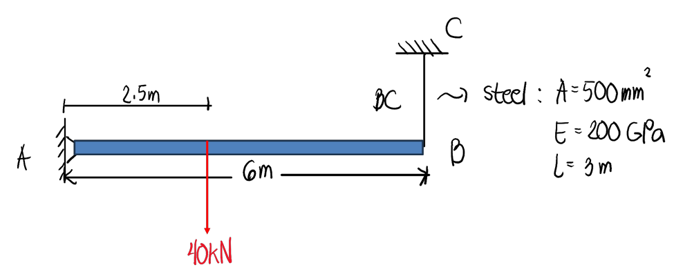
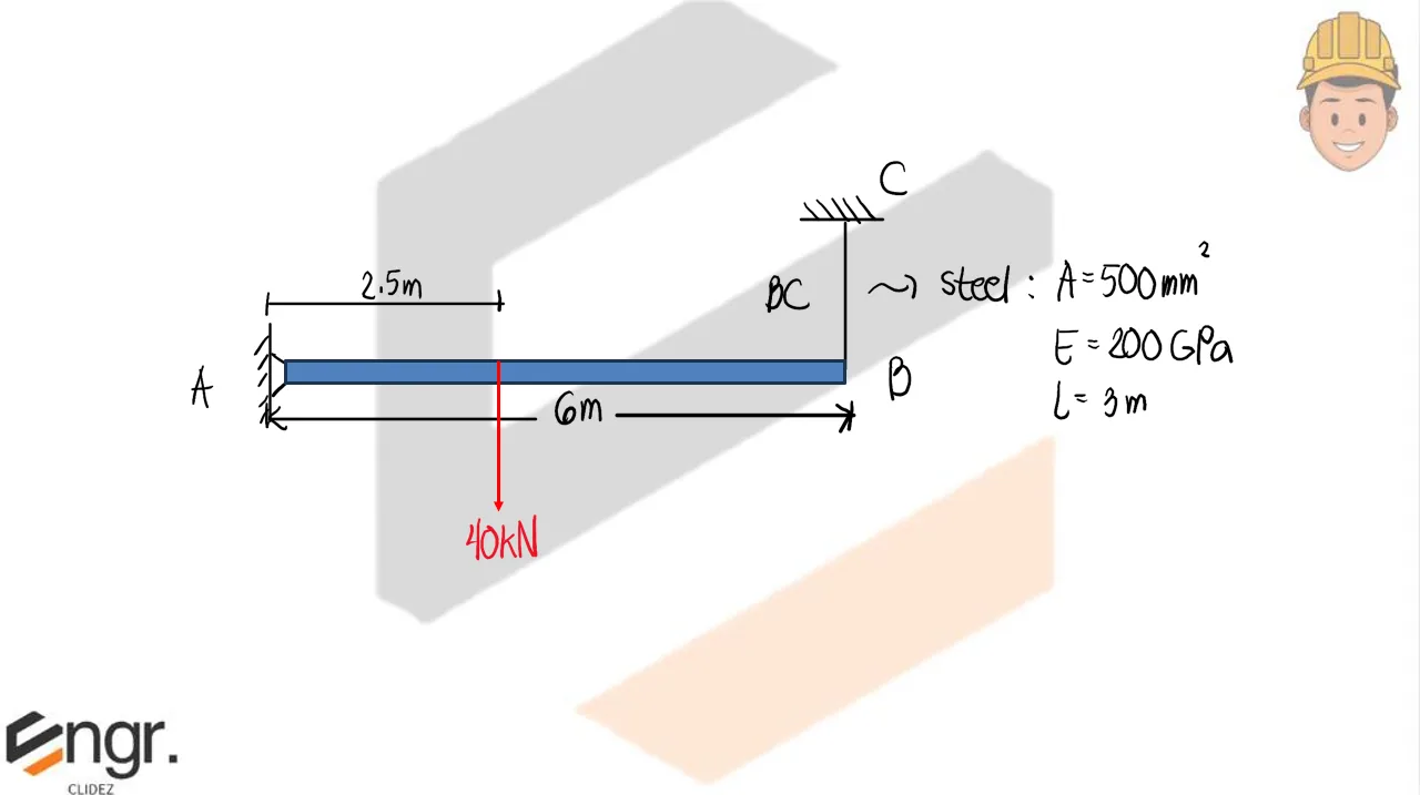
For the assembly shown,

q424

Determine the force in the steel cable, BC.

  1. 16.67kN
  2. 15.00kN
  3. 14.67kN
  4. 16.00kN

Determine the stress in the steel cable.

  1. 33.33MPa
  2. 83.33MPa
  3. 30MPa
  4. 29.33MPa

Determine the deformation of the steel rod.

  1. 0.5001mm
  2. 0.5492mm
  3. 0.6023mm
  4. 0.6341mm
Treat bar $AB$ as a rigid bar pinned at $A$ and supported by the vertical steel cable at $B$. The $40\text{-kN}$ load acts $2.5\text{ m}$ from $A$, while $AB=6\text{ m}$.

Taking moments about $A$:
$$T_{BC}(6)=40(2.5)$$
$$T_{BC}=16.67\text{ kN}$$

The cable area is $A=500\text{ mm}^2$, so its stress is:
$$\sigma=\frac{P}{A}=\frac{16.67\times10^3}{500}=33.33\text{ MPa}$$

Its elongation is found from $\delta=PL/(AE)$. Use $L=3\text{ m}=3000\text{ mm}$ and $E=200\text{ GPa}=200000\text{ N/mm}^2$:
$$\delta=\frac{(16.67\times10^3)(3000)}{(500)(200000)}=0.5001\text{ mm}$$

Therefore, the cable force is 16.67 kN, its stress is 33.33 MPa, and its elongation is 0.5001 mm.

Question Bank: q425

PSAD - Mechanics of Deformable Bodies / Axial Stress / Engr. Janclyde Espinosa (Clidez)

If P=50kN and the cross-sectional area of all members is 1200mm2,
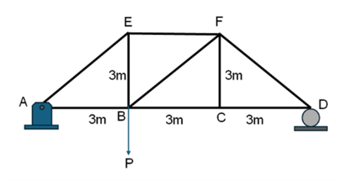
q425

Determine the stress in member BF in MPa.

  1. 19.64
  2. 27.78
  3. 39.28
  4. 13.89

Determine the stress in member EF in MPa.

  1. 27.79
  2. 19.64
  3. 39.28
  4. 13.89
The span is $9\text{ m}$ and the $50\text{-kN}$ load acts at joint $B$, $3\text{ m}$ from $A$. From whole-truss equilibrium:
$$D_y(9)=50(3)\quad\Rightarrow\quad D_y=16.67\text{ kN}$$
$$A_y=50-16.67=33.33\text{ kN}$$

At joint $D$, the $45^\circ$ member $FD$ is found from vertical equilibrium, giving $F_{FD}=23.57\text{ kN}$ in compression. Proceeding through joint $F$ gives:
$$F_{BF}=23.57\text{ kN}\quad\text{(tension)}$$
$$F_{EF}=33.33\text{ kN}\quad\text{(compression)}$$

Every member has area $A=1200\text{ mm}^2$. Hence:
$$\sigma_{BF}=\frac{23.57\times10^3}{1200}=19.64\text{ MPa}$$
$$\sigma_{EF}=\frac{33.33\times10^3}{1200}=27.79\text{ MPa}$$

Therefore, the stress in $BF$ is 19.64 MPa and the stress in $EF$ is 27.79 MPa.

Question Bank: q426

PSAD - Mechanics of Deformable Bodies / Axial Stress / Engr. Janclyde Espinosa (Clidez)

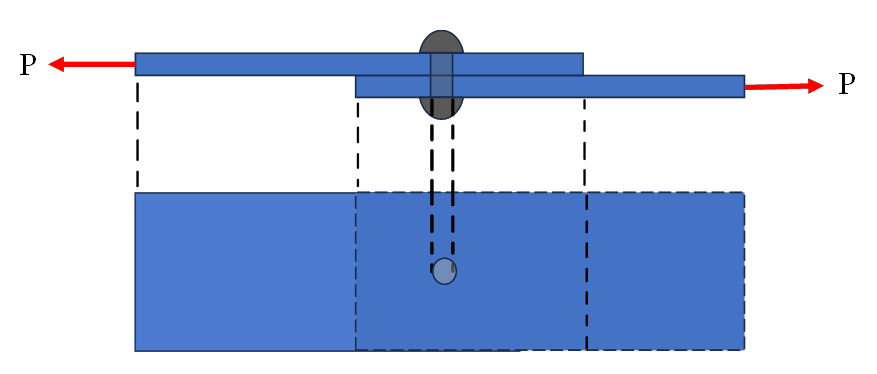
Assume that a 20-mm-diameter rivet joins the plates that are each 110mm wide and 16mm thick.
q426

Determine the shear stress of the bolt if P=10kN

  1. 31.83MPa
  2. 31.25MPa
  3. 27.83MPa
  4. 42.93MPa

Determine the bearing stress of the bolt if P=10kN.

  1. 31.25MPa
  2. 31.83MPa
  3. 27.83MPa
  4. 42.93MPa

Determine the largest average tensile stress in the plate.

  1. 6.94MPa
  2. 5.68MPa
  3. 7.83MPa
  4. 9.62MPa
The figure is a single-lap connection, so the rivet is in single shear. Given $P=10\text{ kN}=10000\text{ N}$, rivet diameter $d=20\text{ mm}$, plate width $w=110\text{ mm}$, and plate thickness $t=16\text{ mm}$:

Shear stress in the rivet
$$A_r=\frac{\pi d^2}{4}=\frac{\pi(20)^2}{4}=314.16\text{ mm}^2$$
$$\tau=\frac{P}{A_r}=\frac{10000}{314.16}=31.83\text{ MPa}$$

Bearing stress
The bearing area is the projected area $dt$:
$$\sigma_b=\frac{P}{dt}=\frac{10000}{20(16)}=31.25\text{ MPa}$$

Largest average tensile stress in a plate
The critical net area passes through the rivet hole:
$$A_{net}=(w-d)t=(110-20)(16)=1440\text{ mm}^2$$
$$\sigma_t=\frac{P}{A_{net}}=\frac{10000}{1440}=6.94\text{ MPa}$$

Therefore, the shear stress is 31.83 MPa, the bearing stress is 31.25 MPa, and the largest average tensile stress is 6.94 MPa.

Question Bank: q546

PSAD - Mechanics of Deformable Bodies / Strain / Engr. Deguma

A copper wire having diameter d = 3 mm is bent into a circle and held with the ends just touching. If the maximum permissible strain in the copper is 0.0024, what is the shortest length L of wire that can be used?

Answer:

  1. 3.93m
  2. 5.62m
  3. 6.28m
  4. 7.12m
For a wire bent into a circular arc, the maximum bending strain is:
$$\epsilon_{max}=\frac{c}{R}=\frac{d/2}{R}$$
Set this equal to the allowable strain $0.0024$:
$$0.0024=\frac{3/2}{R}$$
$$R=625\text{ mm}=0.625\text{ m}$$
The shortest permissible wire is one full circle:
$$L=2\pi R=2\pi(0.625)=3.93\text{ m}$$

Therefore, the shortest length is 3.93 m.

Question Bank: q568

PSAD - Mechanics of Deformable Bodies / Axial Stress and Strain / Engr. Deguma

A polyamide polymer bar has a cross-section of 45mmx45mm and a length of 200mm. The length elongates 3mm when a load of 360kN is applied.

Determine the modulus of elasticity.

  1. 11.85GPa
  2. 8.55GPa
  3. 15.60GPa
  4. 10.11GPa
Use $E=PL/(A\delta)$. With $A=45(45)=2025\text{ mm}^2$, $P=360000$ N, $L=200$ mm, and $\delta=3$ mm:
$$E=\frac{360000(200)}{2025(3)}=11851.85\text{ MPa}=11.85\text{ GPa}$$

Therefore, the modulus of elasticity is 11.85 GPa.

Question Bank: q588

PSAD - Mechanics of Deformable Bodies / Axial Stress and Strain / Mastermatician

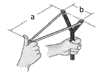
The figure shows a pellet about to be fired from a sling. The total unstretched length of the rubber band is 60mm. The rubber band elongates 1mm for every 15N force.
Given:
a = 100mm
b = 40mm
q588

As the pellet is about to be released, how much is the total elongation of the rubber band?

  1. 144
  2. 102
  3. 42
  4. 204

What is the force exerted on each leg of the rubber band?

  1. 1080
  2. 765
  3. 630
  4. 1530

Determine the pulling force.

  1. 2115
  2. 1500
  3. 1235
  4. 3000
Each stretched leg has length:
$$l=\sqrt{a^2+(b/2)^2}=\sqrt{100^2+20^2}=101.98\text{ mm}$$
The total stretched band length is $2l=203.96$ mm. Hence the total elongation is:
$$\Delta L=203.96-60\approx144\text{ mm}$$
Each leg elongates $144/2=72$ mm. Since the band requires 15 N per millimeter elongation:
$$T=15(72)=1080\text{ N}$$
The pulling force is the sum of the components of the two leg tensions along $a$:
$$P=2T\frac{100}{101.98}=2118\text{ N}\approx2115\text{ N}$$

Therefore, the answers are 144 mm, 1080 N, and 2115 N.

Question Bank: q599

PSAD - Mechanics of Deformable Bodies / Axial Stress and Strain / Mastermatician

A hollow cast-iron pole has an outside diameter of 450mm and an inside diameter of 350mm. It is subjected to a compressive force of 1200 kN (weight included) throughout its length of 1.2m. The pole is braced to prevent bending and buckling. E = 100 GPa

What is the resulting stress due to the compression force, in MPa?

  1. 19.10
  2. 16.10
  3. 12.47
  4. 7.55

Calculate the total contraction of the member due to the compressive force.

  1. 0.23mm
  2. 23mm
  3. 2.3mm
  4. 0.23m

Find the load that would result to a total compressive strain of 0.003 mm/mm.

  1. 1885 kN
  2. 1955 kN
  3. 2155 kN This study
  4. 2000 kN
The annular area is:
$$A=\frac\pi4(450^2-350^2)=62831.9\text{ mm}^2$$
The compressive stress is:
$$\sigma=\frac{1200\times10^3}{62831.9}=19.10\text{ MPa}$$
The shortening is:
$$\delta=\frac{PL}{AE}=\frac{(1200\times10^3)(1200)}{(62831.9)(100000)}=0.23\text{ mm}$$
For a strain of $0.003$, $\sigma=E\epsilon=100000(0.003)=300$ MPa. Thus:
$$P=\sigma A=300(62831.9)=1885\text{ kN}$$

Therefore, the answers are 19.10 MPa, 0.23 mm, and 1885 kN.

Question Bank: t35

PSAD - Mechanics of Deformable Bodies / Axial Stress and Strain / Civil Engineering Refresher

A 12 mm diameter steel bar (L = 18 m) has an allowable stress of 138 MPa.

Find the safe load W it can carry.

  1. 15.6 kN
  2. 13.8 kN
  3. 12.6 kN
  4. 20.0 kN

For the bar in Question 48, find the safe load W if the allowable elongation is 10 mm (E = 200 GPa).

  1. 12.6 kN
  2. 15.6 kN
  3. 18.2 kN
  4. 10.0 kN

Calculate the total strain in the 12 mm steel bar from Question 48 if a load of 20 kN is applied.

  1. 0.00088
  2. 0.00055
  3. 0.00110
  4. 0.00072

Part 1.

$A = \frac{\pi}{4}(12)^2 = 113.1 \text{ mm}^2$.
$W = \sigma A = 138 \times 113.1 = 15{,}607 \text{ N}$
$\boxed{= 15.6 \text{ kN}}$

Part 2.

$\delta = \frac{WL}{AE} \Rightarrow W = \frac{\delta A E}{L}$
$W = \frac{(0.010)(113.1\times10^{-6})(200\times10^9)}{18}$
$\boxed{= 12.6 \text{ kN}}$

Part 3.

$\sigma = \frac{P}{A} = \frac{20000}{113.1} = 176.8$ MPa.
$\varepsilon = \frac{\sigma}{E} = \frac{176.8}{200000}$
$\boxed{= 0.00088}$
Scroll to zoom